1 RESTART RM TOP DISPOSITIVO DI RICHIUSURA AUTOMATICA REGOLABILE PER INTERRUTTORI MODULARI - ADJUSTABLE AUTOMATIC RESET DEVICE FOR MODULAR CIRCUIT BREAKERS - REGULOVATELNÉ ZAŘÍZENÍ PRO AUTOMATICKOU OBNOVU FUNKCE MODULÁRNÍCH PŘÍSTROJŮ ACCOPPIAMENTO - COUPLING - SPOJOVÁNÍ RM TOP + MTC 1...4P MT 1...4P MDC 2...4P MT+BD 2...4P 4P 2P 3P 56mm 3 1P 27mm 2 1 L1 N L2 L3 NO L1 N L2 L3 OK 7 8 9 10 11 12 Negli accoppiamenti con interruttori 1P e 3P la maniglia motore in eccedenza deve essere tagliata. Any excess motor handle after coupling with switches 1P and 3P must be cut off. Při spojování s jističi 1P a 3P, musí být rukojeť motor.pohonu zkrácena 90 RESTART
Transcript
1
RESTART RM TOPDISPOSITIVO DI RICHIUSURA AUTOMATICA REGOLABILE PER INTERRUTTORI MODULARI - ADJUSTABLE AUTOMATIC RESET DEVICE FORMODULAR CIRCUIT BREAKERS - REGULOVATELNÉ ZAŘÍZENÍ PRO AUTOMATICKOU OBNOVU FUNKCE MODULÁRNÍCH PŘÍSTROJŮ
ACCOPPIAMENTO - COUPLING - SPOJOVÁNÍ
RM TOP
+
MTC 1...4P
MT 1...4P
MDC 2...4P
MT+BD 2...4P
4P 2P
3P56mm
3
1P27mm
2
1
L1 NL2 L3
NO
L1N L2 L3
OK
7 8 9 10 11 12
Negli accoppiamenti con interruttori 1P e 3P la maniglia motore in eccedenza deve essere tagliata.Any excess motor handle after coupling with switches 1P and 3P must be cut off.Při spojování s jističi 1P a 3P, musí být rukojeť motor.pohonu zkrácena
90 RESTART
I-ON
0-OFF
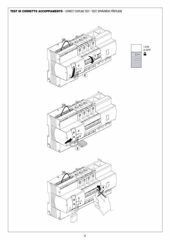
1
3
4
2
I-ON0-OFF
I-ON
0-OFF
I-ON
0-OFF
TEST DI CORRETTO ACCOPPIAMENTO - CORRECT COUPLING TEST - TEST SPRÁVNÉHO PŘIPOJENÍ
2
1
2
3 4
3
Modulo di controllo del cortocircuitoShort circuit detection moduleModul kontroly zkratu
INSTALLAZIONE - INSTALLATION - INSTALACE
NO
OR
Il modulo di rilevamento del cortocircuito può essere installato sia a monte che a valle dell’interruttore.The short-circuiting detection module can be installed either upstream or downstream from the circuit breaker. Modul kontroly zkratu může být instalován shora či ze spodu jističe
Nel caso l’interruttore sia affiancato da un blocco differenziale, il modulo non può essere installato direttamente ai morsetti di uscita del differenziale.If the circuit breaker is coupled with a residual current device, the module cannot be directly installed on the output terminals of the residual current device.V případě, že k jističi bude připojen diferenciální blok, modul nelze připojit přímo na výstupní svorky dif.bloku
4
MTMDC
MT+BD
L’installazione di RM TOP accoppiato conMTC, richiede la delocalizzazione delmodulo di rilevamento del corto circuito.The installation of the RM TOP coupled withthe MTC requires the delocalisation of theshort-circuit detection module.Instalace RM TOP s připojeným kompaktnímjističem MTC, vyžaduje jiné umístění modulukontroly zkratu
≤ 35 mm2≤ 35 mm2
5
6
7
L1 NL2 L3
NO
I-ON0-OFF
Intervenire solo ad impianto sezionato e quindi con dispositivo non inserito (porre il selettore in posizione di lucchettato).Intervention is only permitted when the system is isolated and the device has been switched off (put the selector in the padlocked position)Zasahovat pouze, pokud je obvod odpojen a Restart vypnut (přepínač do pozice k zamknutí)
5
Connettere l’alimentazione del dispositivo tra una fase e il neutro(cavo nero-fase, cavo blu-neutro)Wire the device’s power supply between one phase and neutral (black cable-phase, blue cable neutral)Připojit napájení zařízení mezi F a N (F-černý vodič, N-modrý vodič)
Nelle configurazioni trifase il neutro deve essere sempre collegato nell’ultimo polo a sinistra dell’interruttore.In three-phase configurations the neutral must always be connected in the last pole to the left of the switch.Při konfiguraci 3-F, vodič N musí být vždy připojen na poslední pól jističe vlevo.
6
789 10
1112
8
230V~
OPEN CLOSERESET
789 10
11
3
0,4 Nm2,5 mm²
789 10
1112
0,4 Nm2,5 mm²
3
789 10
1112
3
0,4 Nm2,5 mm²
AUX1
AUX2
9 789 10
1112
0,4 Nm2,5 mm²
3
7
Nel caso non sia sufficiente lo spazio per l’installazione del modulo di rilevamento cortocircuito, è possibile delocalizzarlo sulla guida DINtramite morsetti (non inclusi nel kit).If there is not enough space to install the short-circuiting detection module, you can delocalise it on the DIN rail, through terminals (not supplied withthe kit).V případě, že není dost místa k instalaci modulu kontroly zkratu, je možné ho umístit na lištu DIN s pomocí svorek (nejsou součástí KITu)
L’alimentazione deve essere sempre prelevata tra fase e neutro. (*) Isolare i cavi e i terminali non utilizzati.The power supply must always be taken between phase and neutral. (*) Insulate the unused cables and terminals.Napajení se musí vždy vzít z F a N. (*) Izolujte nepoužité vodiče a svorky.
1 2 3 4 5 6 7 8 9101112
N L1 L2 L3
7 8 9 10 11 12 7 8 9 10 11 12 7 8 9 10 11 12
E’ possibile utilizzare il riarmo da remoto sia nella configurazione con controllo dell’impianto che senza controllo.It is possible to use the remote reset in the configurations both with and without system control.Je možné použít dálkový reset v konfiguraci s kontrolou obvodu nebo bez kontroly.
9
Comando a pulsantiPush-button commandOvládání tlačítky
Comando ciclicoCyclical commandCyklický příkaz
Comando mantenutoHeld commandPříkaz přidržení
L’installazione di RM TOP accoppiato con MTC, richiede la delocalizzazione del modulo di rilevamento del corto circuito.The installation of the RM TOP coupled with the MTC requires the delocalisation of the short-circuit detection module.Instalace RM TOP s připojeným kompaktním jističem MTC, vyžaduje jiné umístění modulu kontroly zkratu
10
I-ON0-OFF
I-ON0-OFF
I-ON
0-OFF
LED ON2 LED OFF4 LED OFF6
R R R
I-ON
0-OFF
789 10
1112
1
789 10
1112
I-ON
0-OFF
3I-O
N
0-OFF
789 10
1112
5
ATTIVAZIONE/DISATTIVAZIONE RM TOP - ACTIVATION/DEACTIVATION RM TOP - AKTIVACE/DEAKTIVACE RM TOP
RM TOP ON RM TOP LOCKED
TEST MANUALE DI INTERVENTO DIFFERENZIALE - MANUAL DIFFERENTIAL INTERVENTION TEST MANUÁLNÍ TEST PROUDOVÉHO CHRÁNIČE
N.B. Il test deve essere effettuato men-silmente. Se l’interruttore differenzialenon interviene chiamare un tecnico perla verifica dell’apparecchio.N.B. The test must be carried out mon-thly. Call a technician to check the deviceif the residual current device does not trip.Pozn.: Test se musí provádět měsíčně.Pokud chránič neintervenuje, zavolejtetechnika.
RM TOP OFF
I-ON
0-OFF
789 10
1112
I-ON
0-OFF
1 ON
2
3
789 10
1112
I-ON
0-OFF
4
Impostando il selettore in posizione di OFF o di lucchettato il dispositivo è disattivato.Setting the selector to the OFF or locked position, the device is deactivated.Přístroj je deaktivován, pokud je přepínač v pozici OFF nebo zamknut
I-ON
0-OFF
789 10
1112
I-ON
0-OFF
1 ON
LED ON
R
789 10
1112
I-ON
0-OFF
2
3
11
TEST DI RICHIUSURA AUTOMATICA CON VERIFICA PREVENTIVA DELL’IMPIANTO - AUTOMATIC RESET TEST WITH PREVENTIVESYSTEM CHECK - TEST AUTOMATICKÉHO RESTARTU S PREVENTIVNÍ KONTROLOU OBVODU
Alla prima messa in servizio, far scattare l’interruttore premendo il tasto di test. Aspettare la richiusura automatica. Nel caso il ciclo di riarmonon venga concluso correttamente verificare l’isolamento verso terra dell’impianto, che deve superare i 16 kΩ per I∆n 30mA, 5 kΩ per I∆n300mA.At the initial start-up, trigger the circuit breaker by pressing the test button key. Wait for the automatic reset. If the reset cycle is not completed correctly,check the system's earthing insulation (which must exceed 16 kΩ per I∆n 30mA, 5kΩ per I∆n 300mA).Při prvním zapojení do sítě, nechte chránič vypnout stisknutím testovacího tlačítka. Vyčkejte na automatický restart. Jestliže cyklus neproběhne správně,zkontrolujte izolaci proti zemi, která musí být vyšší než 16 kΩ pro IΔn 30mA, 5kΩ pro IΔn 300mA.
RICHIUSURA AUTOMATICA CON VERIFICA PREVENTIVA DELL’IMPIANTO - AUTOMATIC RESET WITH PREVENTIVE SYSTEM CHECK -AUTOMATICKÝ RESTART S PREVENTIVNÍ KONTROLOU OBVODU
Regolare il selettore R in base al valore di I∆n dell’interruttore differenziale accoppiato.Adjust the selector R on the basis of the value of I∆n of the associated residual current circuit breaker.Nastavte přepínač R na hodnotu IΔn připojeného proudového chrániče
Il selettore T permette di regolare il tempo che intercorre tra l’intervento dell’interruttore e laverifica dell’impianto. L’impostazione 0’’ permette una verifica immediata.The selector T allows you to adjust the time lapse between the tripping of the circuit breaker and thesystem check. Set "0’’ to obtain an immediate check.Přepínač T umožňuje nastavení času mezi intervencí přístroje a kontrolou obvodu. Čas "0" znamenáokamžité zahájení kontroly
0’’ 30’’
5’
1’
15’30’
T
TRIP CHECK
5 min
1h
iT
12
78910
1112
I-ON
0-O
FF
78910
1112
I-ON
0-O
FF
CLAC
K
78910
1112
I-ON
0-O
FF
78910
1112
I-ON
0-O
FF
CLAC
K
IN CASO DI INTERVENTO DELL’INTERRUTTORE - SHOULD THE CIRCUIT BREAKER TRIP - V PŘÍPADĚ INTERVENCE MODULÁR. PŘÍSTROJELE
D ro
sso
lam
pegg
iant
e: v
erifi
-ca
impi
anto
max
10s
.Re
d LE
D bli
nking
: insta
llatio
nch
eck
max
. 10s
.Če
rven
á LE
D bl
iká:
prob
íhá
kont
rola
inst
alac
e, m
ax. 1
0s.
Scat
to in
tem
pest
ivoUn
timely
tripp
ingNá
hodn
é vy
pnut
í
Riar
mo
OK- R
eset
OK -
Rest
art O
K
Guas
to im
pian
toFa
ult to
ear
thPo
ruch
a v
obvo
du.
LED
ross
o fiss
o: sta
to d
i bloc
co. A
vvien
e qua
ndo i
l disp
o-sit
ivo h
a rile
vato
un
corto
circu
ito n
ell’im
piant
o opp
ure a
caus
a di q
uattr
o sga
nci c
onse
cutiv
i in 60
s.Fix
ed re
d LE
D: b
locka
ge st
atus
. This
occ
urs w
hen
the
devic
e ha
s det
ecte
d a
shor
t-circ
uit in
the
syste
m, o
r fol-
lowing
four
cons
ecut
ive re
lease
s in
60 se
c.Če
rven
á LE
D tr
vale
sví
tí: s
tav
blok
ace.
Ten
to s
tav
nast
ane,
pok
ud re
star
t det
ekuj
e zk
rat v
obv
odu
aneb
odo
jde
běhe
m 6
0s k
e 4
po s
obě
násl
eduj
ícím
výpa
dkům
.LE
D ro
sso s
emi-i
nter
mitt
ente
: il d
ispos
itivo
ha m
isura
to u
n ba
sso l
ivello
di
isolam
ento
dell
’impi
anto
e si
pone
in st
ato d
i atte
sa. O
gni 1
5’ ve
rrà ri
effe
ttuat
aun
a ver
ifica
dell
’impi
anto
e in
caso
di e
sito p
ositi
vo l’
inte
rrutto
re ve
rrà ri
chiu
so.
Sem
i-int
erm
itten
t red
LED
:the
dev
ice h
as m
easu
red
a low
leve
l of s
yste
m in
sula-
tion,
and
is in
stand
by.A
syste
m ch
eck
will b
e ca
rried
out
eve
ry 1
5’ a
nd, in
the
even
t of a
pos
itive
resu
lt, th
e cir
cuit
brea
ker w
ill be
rese
t.Če
rven
á LE
D po
blik
ává.
Res
tart
nam
ěřil
nízk
ou h
odno
tu iz
olac
e pr
oti z
emi a
uve
dlse
do
stav
u če
kání
. Kaž
dých
15´
bud
e ov
ěřen
obv
od a
v p
řípad
ě po
zitiv
ního
výsl
edku
, doj
de k
sep
nutí.
(pag
. 6)
RICHIUSURA AUTOMATICA SENZA VERIFICA PREVENTIVA DELL’IMPIANTO - AUTOMATIC RESET WITHOUT PREVENTIVE SYSTEMCHECK - AUTOMATICKÝ RESTART BEZ PREVENTIVNÍ KONTROLY OBVODU
Impostare tramite il selettore R il numero massimo di richiusure automatiche successive.By means of the selector R, set the maximum number of consecutive automatic reset operations.Nastavte přepínač R na maximální hodnotu následujích automatic.operací
OFF 1
5
2
3
10
R
CHECK 30mA
CHECK 300mA1,2,3,5,10Reclosing
Impostare tramite il selettore T l’intervallo di tempo che intercorre tra l’intervento dell’interruttore e la richiusura automatica.Use the selector T to set the time lapse between the tripping of the circuit breaker and the automatic reset.Nastavte přepínač T na časový interval, který má proběhnout mezi intervencí jističe a automatic.restartem
0’’ 30’’
5’
1’
15’30’
T
TRIP 1° RECLOSING
30’’
1h
iT
30’’
X n
2° RECLOSING
La selezione del tempo T permette di impostare un intervallo di tempo crescente con l’aumentare dei tentativi di richiusura successivi.By selecting the time iT, you can set a time lapse that increases with the growing number of subsequent reset attempts.Volba ΔT umožňuje nastavení rostoucího časového intervalu s rostoucím počtem pokusů o restart
13
0’’ 30’’
5’
1’
15’30’
T1°
1h
iT
30’’
2°
R OFF 1
5
2
3
10
3° 4° 5° 6° 7° 8° 9° 10°
1’ 5’ 15’ 30’ 1h 3h 6h 12h
N° tentativo di richiusuraNo. of reset attempts.Počet pokusů o restart
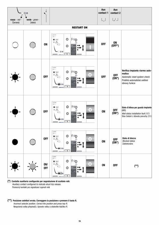
rosso - red - Červená verde - green - Zelená
Aux contact 1
14
SEGNALAZIONE DEI LEDLED SIGNALS - SIGNALIZACE LED
ON
OFF
OFF
OFF
RESTART OFF
R
R
Aux contact 2
ON(OFF*)
OFF
(*) Contatto ausiliario configurato per segnalazione di scattato relè.Auxiliary contact configured to indicate shunt trip release.Pomocný kontakt pro signalizaci vypnutí relé
LEGENDA - KEY - LEGENDA:
LED lampeggiante - LED blinking - LED bliká
LED semi-intermittente - LED semi-intermittent - LED svítí přerušovaně
LED fisso - LED fixed - LED svítí trvale
15
ON
OFF
OFF
OFF
ON/OFF
OFF
OFF
ON
ON
ON
R
R
R
R
R
Verifica impianto riarmo auto-maticoAutomatic reset system checkProbíhá automatické ověřeníobnovy funkce
Stato d’attesa per guasto impianto(15’)Wait status installation fault (15’)Stav čekání z důvodu poruchy (15´)
Stato di bloccoBlocked statusZablokováno
RESTART ON
Aux contact 1
Aux contact 2
ON(OFF*)
OFF(ON*)
OFF(ON*)
OFF(ON*)
OFF
(**) Posizione selettori errata. Correggere la posizione e premere il tasto R.Incorrect selector position. Correct the position and press key R.Nesprávná volba přepínačů. Upravte volbu a stiskněte tlačítko R.
(**)
(*) Contatto ausiliario configurato per segnalazione di scattato relè.Auxiliary contact configured to indicate shunt trip release.Pomocný kontakt pro signalizaci vypnutí relé
rosso - red -Červená
verde - green -Zelená
IN CASO DI LED ROSSO FISSO - WHEN A FIXED RED LIGHT - POKUD ČERVENÁ LED SVÍTÍ TRVALE
16
Contattare un tecnico specializzato perchè la sicurezza dell’impianto potrebbe essere diminuita. Una volta ripristinata la sicurezzadell’impianto è possibile resettare la segnalazione di LED rosso fisso chiudendo manualmente l’interruttore o tramite il comando diRESET da remoto.Contact a specialised technician, as system safety could be reduced. Once the system safety level has been restored, you can reset the lightsignalling of the fixed red LED by manually activating the circuit breaker, or via the remote RESET command.Kontaktujte technika, protože bezpečnost obvodu by mohla porušena. Pokud bude závada odstraněna, můžete resetovat signaliazaci červenéLED manuálním sepnutím jističe nebo příkazem RESET vzdálené kontroly.
IN CASO DI LED ROSSO E VERDE LAMPEGGIANTI - IF THE RED AND GREEN LEDS ARE BLINKING - POKUD ČERVENÁ LED BLIKÁ
I selettori R o T sono regolati in modo errato su valori non esistenti (in posizione intermedia tra un valore di selezione e l’altro).Correggere la regolazione.The R or T selector is incorrectly set on a non-existent value (in an intermediate position between one selection value and another). Correctthe setting.Přepínače R a T jsou v nesprávné poloze nastaveny na neexistující hodnoty (v mezipoloze). Opravte nastavení
Nel caso la segnalazione dei LED non dovesse corrispondere a quanto riportato in tabella a pag. 15 contattare un tecnicospecializzato.If the LED light signalling does not correspond with the indications in the table pag. 15, contact a specialised technician.Pokud signalizace LED neodpovídá tabulce na str.15, kontaktujte technika.
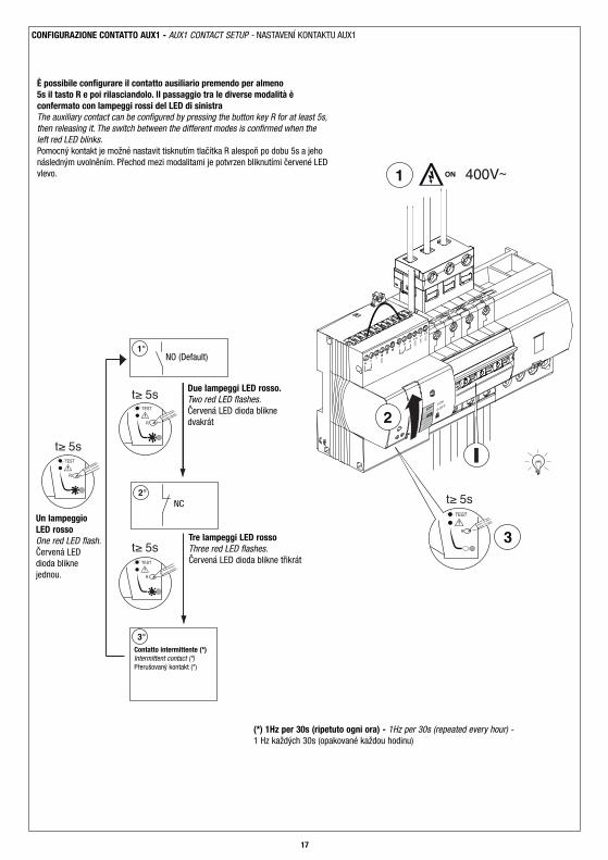
È possibile configurare il contatto ausiliario premendo per almeno 5s il tasto R e poi rilasciandolo. Il passaggio tra le diverse modalità èconfermato con lampeggi rossi del LED di sinistraThe auxiliary contact can be configured by pressing the button key R for at least 5s,then releasing it. The switch between the different modes is confirmed when theleft red LED blinks.Pomocný kontakt je možné nastavit tisknutím tlačítka R alespoň po dobu 5s a jehonásledným uvolněním. Přechod mezi modalitami je potvrzen bliknutími červené LEDvlevo.
Un lampeggioLED rossoOne red LED flash.Červená LEDdioda bliknejednou.
NO (Default)
Tre lampeggi LED rossoThree red LED flashes.Červená LED dioda blikne třikrát
NC
Due lampeggi LED rosso.Two red LED flashes.Červená LED dioda bliknedvakrát
Contatto intermittente (*)Intermittent contact (*)Přerušovaný kontakt (*)
(*) 1Hz per 30s (ripetuto ogni ora) - 1Hz per 30s (repeated every hour) -1 Hz každých 30s (opakované každou hodinu)
Sistema di distribuzione: TT – TN - (IT riarmo senza controllo impianto)Tensione nominale di impiego Ue: 230VacPotenza assorbita a vuoto: 15VA (cosϕ=0,06)Potenza assorbita in fase di riarmo: 30VA (cosϕ=0,65)Potenza dissipata a In: potenza dissipata dell’interruttore associatoTensione di isolamento verso massa: 2500Vac per 1 minutoTensione nominale di tenuta ad impulso Uimp: 4kVResistenza nominale verso terraNon funzionamento Rd: 8kΩ (In30), 2,5kΩ (In300)Funzionamento Rd0: 16kΩ (In30), 5kΩ (In300)Resistenza nominale tra le parti attiveFunzionamento Rcc0: 1,8ΩNon funzionamento Rcc: 0,3ΩNumero massimo di richiusure senza test: 10Regolazione ritardo chiusura: 0÷1hTempo di richiusura: <3s (<10s con test)Tempo di apertura da remoto: <2sSpazio occupato: 4ModuliTemperatura d’impiego: da -5°C a +40°CIP20Contatto ausiliario AUX1: 5÷230Vac/dc Imax 100mA(cosφ=1), Imin 0,6mA / AC12Contatto ausiliario in scambio AUX2: 1,5A (230Vac) - 0,8A (30Vdc) / AC12Le caratteristiche tecniche ed elettriche sono le medesimedell’interruttore associato.
Distribution system: TT - TN - (IT reset without system check)Rated operational voltage Ue: 230VacOff-load absorbed power: 15VA (cosϕ=0,06)Reclosing absorbed power: 30VA (cosϕ=0,65)Dissipated power at In: dissipated power of the associated RCCBInsulation voltage to earth: 2500Vac for 1 min.Rated impulse withstand voltage Uimp: 4kVRated resistance to groundOperating Rd0 : 16kΩ (IΔn30), 5kΩ (IΔn300)Non operating Rd : 8kΩ (IΔn30), 2,5kΩ (IΔn300)Rated resistance between the live partsOperating Rcc0 : 1,8ΩNon operating Rcc : 0,3ΩMaximum number of reset operations without test: 10Reset delay adjustment: 0÷1hTime of reclosing: <3s (<10s with test)Remote opening time: <2sWidth: 4 ModulesOperating temperature: from -5°C to +40°C:IP20Auxiliary contact AUX1: 5÷230Vac/dc Imax 100mA(cos=1), Imin 0,6mA / AC12Change-over auxiliary contact AUX2: 1,5A (230Vac) - 0,8A (30Vdc) / AC12The technical and electrical features are the same as the RCCB fitted.
Systém rozvodu TT-TN (IT reset bez kontroly obvodu)Nominální napětí Ue: 230VacSpotřeba naprázdno: 15VA (cosϕ=0,06)Spotřeba při automat.restartu: 30VA (cosϕ=0,65)Ztrátový výkon při In:Ztrátový výkon proudového chráničeIzolační napětí proti zemi: 2500Vac na 1 min.Odolnost na impulzní napětí Uimp: 4kVJmenovitý odpor k zemiNefunkční Rd0: 8kΩ (IΔn30), 2,5kΩ (IΔn300)Funkční Rd0: 16kΩ (IΔn30), 5kΩ (IΔn300)Jmenovitý odpor mezi živými částmiFunkční Rcc: 1,8ΩNefunkční Rcc: 0,3ΩMaximální počet pokusů o restart bez testu:10Nastavení zpoždění restartu: 0÷1hDoba znovusepnutí <3s (<10s s testem)Doba otevření při vzdáleném ovládání <2sPočet modulů DIN: 4 moduliTeplota instalace: od -5°C do +40°C (průměrná denní ≤35°C)IP20Pomocný kontakt AUX1: 5÷230Vac/dc Imax 100mA(cosφ=1),Imin 0,6mA / AC12Přepínací pomocný kontakt AUX2: 1,5A (230Vac) - 0,8A (30Vdc) / AC12Technické a elektrické vlastnosti jsou stejné jako připojeného přístroje (jističe/chrániče)
CARATTERISTICHE TECNICHE - TECHNICAL FEATURES - TECHNICKÉ PARAMETRY
92
6 44
45
50
7 8 9 10 11 12
62.41872
106
35
DIMENSIONI - DIMENSIONS - ROZMĚRY
cod.
7.4
2.9.
328.
3UL
TIM
A RE
VISI
ONE
04/2
012
24h
Ai sensi dell’articolo 9 comma 2 della Direttiva Europea 2004/108/CE e dell’articolo R2 comma 6 della Decisione 768/2008/CE si informa che responsabile dell’immissionedel prodotto sul mercato Comunitario è:According to article 9 paragraph 2 of the European Directive 2004/108/EC and to article R2 paragraph 6 of the Decision 768/2008/EC, the responsible for placing theapparatus on the Community market is:GEWISS S.p.A Via A. Volta, 1 - 24069 Cenate Sotto (BG) Italy Tel: +39 035 946 111 Fax: +39 035 945 270 E-mail: [email protected]