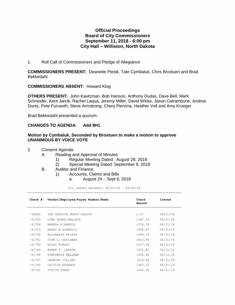
Official Proceedings Board of City Commissioners September 11, 2018 - 6:00 pm City Hall – Williston, North Dakota 1. Roll Call of Commissioners and Pledge of Allegiance COMMISSIONERS PRESENT: Deanette Piesik, Tate Cymbaluk, Chris Brostuen and Brad Bekkedahl COMMISSIONERS ABSENT: Howard Klug OTHERS PRESENT: John Kautzman, Bob Hanson, Anthony Dudas, Dave Bell, Mark Schneider, Kent Jarcik, Rachel Laqua, Jeremy Miller, David Wicke, Jason Catrambone, Andrea Duntz, Pete Furuseth, Steve Armstrong, Chery Pierzina, Heather Voll and Amy Krueger Brad Bekkedahl presented a quorum. CHANGES TO AGENDA: Add 8H1 Motion by Cymbaluk, Seconded by Brostuen to make a motion to approve UNANIMOUS BY VOICE VOTE 2. Consent Agenda A. Reading and Approval of Minutes 1) Regular Meeting Dated: August 28, 2018 2) Special Meeting Dated: September 6, 2018 B. Auditor and Finance 1) Accounts, Claims and Bills a. August 24 – Sept 6, 2018 For checks between: 08/24/18 - 09/06/18 Check # Vendor/Employee/Payee Number/Name Check Amount Issued -99899 JOB SERVICE NORTH DAKOTA 2.57 08/31/18 -41755 LYNN BYERS-WALLACE 1387.37 08/31/18 -41754 BRENDA D'ANGELO 1574.78 08/31/18 -41753 RANDY M DONNELLY 1900.67 08/31/18 -41752 ELIZABETH HEISEY 1999.35 08/31/18 -41751 JOHN L. KAUTZMAN 3603.80 08/31/18 -41750 KATHY KIMLEY 2227.38 08/31/18 -41749 KAREN P. LARSON 1802.81 08/31/18 -41748 STEPHANIE WELLMAN 1496.62 08/31/18 -41747 JASMINE COLLINS 1516.68 08/31/18 -41746 CAITLIN ESTRADA 1387.37 08/31/18 -41745 JUSTIN FREED 1402.35 08/31/18
Transcript
66
20. ročník - č. 3/2011
1 ÚVOD
V lednu 2009 přestala platit předběžná evropská ocelářskánorma ČSN P ENV 1993-1-1 a v dubnu 2010 byla ukončena plat-nost souběžné platné české ocelářské normy ČSN 73 1401. Od tédoby je nutné při návrhu ocelových konstrukcí postupovat podlejediné platné normy ČSN EN 1993-1-1 Eurokód 3: Navrhováníocelových konstrukcí – Část 1-1: Obecná pravidla a pravidla propozemní stavby [1] (dále jen norma). Požadavky uvedenév normě se vztahují i na ocelové konstrukce používanév podzemním stavitelství, jako jsou například válcované profilydůlní výztuže.
2 OCELOVÁ DŮLNÍ VÝZTUŽ
Válcované profily důlní ocelové výztuže jsou dnes používánypředevším při ražbě štol a při hloubení jam, stavebních šacheta šachtic. Hlavní výhodou ocelové důlní výztuže je schopnostpřenášet zatížení ihned po instalaci, na rozdíl od příhradovévýztuže typu Bretex, kterou je nutné doplnit stříkaným betonem,čímž vzniká určitá časová prodleva mezi instalací výztužea schopností staticky působit. Další výhodou je značná tvarovávariabilita příčného řezu, mezi základní tvary patří podle [8]:
– LA ... lichoběžníkový průřez se sklonem bočních stran 1:4– LB ... lichoběžníkový průřez se sklonem bočních stran 1:6– KC ... kruhový průřez– OO ... obloukový průřez s bočními stranami průběžně zaob-
lenými– OR ... obloukový průřez s rovnými konci rovných dílů
V ČR se používají především tzv. korýtkové profily (značí sepísmenem K) a profily typu Toussaint-Heintzmann (značí se pís-menem TH), které vyrábí Acelor Mittal Ostrava, a. s.
Za tímto značením následuje číslice, která udává zaokrouhle-nou hmotnost profilu v kg na 1 metr (přesná hmotnost jednohometru profilu K21 je 20,74 kg a profilu TH21 je 20,92 kg).
Pro výrobu nejčastěji používaného profilu K21 se používá ocelznačky 11 500.0, jejíž mechanické vlastnosti a chemické složeníjsou uvedeny v [6]. Tato ocel má mez kluzu 295 MPa a pevnostv tahu 470 ÷ 610 MPa. Pro výrobu profilu TH21 se používá ocelznačky 31 Mn 4, jejíž mechanické vlastnosti a chemické složeníjsou uvedeny v [7]. Tato ocel má mez kluzu 350 MPa a minimálnípevnost v tahu 550 MPa. (Tab. 1)
3 NÁVRH A POSOUZENÍ OCELOVÉ DŮLNÍ VÝZTUŽE
Ocelová důlní výztuž se spojuje do rámů, které jsou většinoukolmé na osu díla. Při návrhu příčného řezu díla je vhodné vychá-zet z geometrického tvaru rámů, který je obvykle předepisován,viz např. [8]. Při posouzení rámové konstrukce výztuže je nutnépodle [1] provést následující kroky:
1. klasifikace průřezu 2. klasifikace soustavy
1 INTRODUCTION
In January 2009, the preliminary European steel-related standardČSN P ENV 1993-1-1 became invalid and, in April 2010, the vali-dity of the parallel Czech standard ČSN 73 1401 was terminated.Since then it has been necessary when designing steel structures toproceed according to the only valid standard ČSN EN 1993-1-1Eurocode 3: Design of steel structures – Part 1-1: General rules andrules for building [1] (hereinafter referred to as the standard). Therequirements contained in the standard even relate to steel structuresused in the underground construction industry, e.g. support framesfrom rolled steel sections.
2 STEEL COLLIERY SUPPORT FRAMES
Rolled profiles for steel colliery supports are today used first of allduring the excavation of adits, construction pits, construction shaftsand manholes. The main advantage of steel colliery support is itsability to carry loads immediately after installation, in contrast withBretex-type lattice girders, which must be complemented by shotc-rete, owing to which fact the ability to take loads lags behind themoment of the support installation. Another advantage is the signi-ficant variability of the cross-section; according to [8], there are thefollowing basic geometries:
– LA ... trapezoidal cross section with the sides inclining at 1:4– LB ... trapezoidal cross section with the sides inclining at 1:6– KC ... circular cross section– OO ... vaulted cross section with continuously rounded sides – OR ... vaulted cross section with straight ends of straight parts
Trough sections (marked by letter K) and Toussaint-Heintzmannprofiles (marked TH) produced by Acelor Mittal Ostrava a.s. aremost frequently used in the Czech Republic.
The above mark is followed by a figure stating the rounded weightof the profile in kg per 1 metre (the exact weight of one metre ofK21 and TH profiles is 20.74 kg and 20.92 kg, respectively).
Steel grade 11 500.0, the mechanical properties and chemicalcomposition of which are presented in [6], is used for the producti-on of the most frequently used profile, K21. This steel has the yieldstrength of 295 MPa and the tensile strength of 470 ÷ 610. Steel qua-lity 31 MN 4 is used for the production of TH21 profiles. Its mecha-nical properties and chemical composition are presented in [7]. Thissteel has the yield strength of 350 MPa and the minimum tensilestrength of 550 MPa. (Table 1)
3 DESIGN AND ASSESSMENT OF STEEL COLLIERY SUPPORT FRAMES
Elements of steel colliery support frames are joined together toform frames, which are mostly perpendicular to the tunnel centreline. When a cross-section of the tunnel is being designed, it is rea-sonable to start from the geometrical shape of the frames, which isusually prescribed, see e.g. [8]. The following steps have to be
POSOUZENÍ DŮLNÍ OCELOVÉ LICHOBĚŽNÍKOVÉ VÝZTUŽE PODLE ČSN EN 1993-1-1 EUROKOD 3
ASSESSMENT OF STEEL COLLIERY SUPPORT FOR TRAPEZOIDALFRAME ACCORDING TO ČSN EN 1993-1-1 EUROCODE 3
JAKUB DOLEJŠ, MICHAL SEDLÁČEK
67
20. ročník - č. 3/2011
3. zavedení počátečních imperfekcí4. volba typu stabilitního výpočetního postupu5. provedení globální analýzy (výpočtu vnitřních sil) 6. posouzení v mezním stavu únosnosti – stabilitní posouzení
pro ohyb a osový tlak (interakční podmínky)7. posouzení spoje, tzn. odpor výztuže proti prokluzu8. posouzení v mezním stavu použitelnosti
3.1 Klasifikace průřezu
Norma [1] (dále jen norma) umožňuje provedení plastické globál-ní analýzy, tedy výpočtu vnitřních sil za předpokladu vzniku plastic-kých kloubů na prutové konstrukci. Plastická globální analýza obvy-kle vede k hospodárnějšímu návrhu, ovšem může být provedena jenpři splnění normou udaných podmínek (odst. 5.6 normy).
Jedná se zejména o dostatečnou rotační kapacitu průřezuv místě vytvoření plastického kloubu. Ta se ověřuje pomocí tzv.klasifikace průřezu, tedy přiřazení třídy průřezu. Jsou rozlišeny 4třídy průřezu označované číslicemi 1–4 (tabulka 5.2 normy), při-čemž plastickou globální analýzu umožňují jen průřezy třídy 1.
Klasifikace se provádí na základě:– tvaru průřezu (zejména poměru tloušťky a šířky jednotlivých
částí průřezu),– rozdělení napětí po průřezu (ohyb, tlak, ohyb + tlak),– maximálního dosaženého napětí (meze kluzu).Zatřídění průřezu bude využito i později při posouzení průřezu
a prutu.
3.2 Klasifikace soustavy
Na základě klasifikace průřezu se může uživatel rozhodnoutbuď pro plastickou globální analýzu, nebo pro pružnou. Pro rámtvořený prvky s průřezem třídy 1 je možná plastická varianta, proostatní pouze pružná.
Dále je nutné klasifikovat soustavu (rám) s ohledem na stabilit-ní chování. V přednormě [7] byly zavedeny výrazy „posuvné“,resp. „neposuvné“ styčníky, které výstižně popisovaly chovánírámu při vybočení prutů v rovině. Norma [1] už tyto výrazy proklasifikaci neužívá a zatřídění rámu se provádí na základě stabi-litního výpočtu. Ověřuje se podmínka
v případě pružné analýzy a(3)
v případě plastické analýzy, kde
Fcr je kritické zatížení pro celkové vybočení,FEd je návrhové zatížení konstrukce.Pokud je podmínka (3) splněna, postačí provedení globální ana-
lýzy 1. řádu s uvážením počáteční geometrie konstrukce. Pro
conducted according to [1] when assessing a supporting framestructure:
1. classification of the cross-section 2. classification of the system3. introduction of initial imperfections4. selection of the type of the stability calculation procedure 5. execution of a global analysis (calculations of inner forces) 6. assessment for the ultimate limit state – stability assessment for
bending and axial pressure (interaction conditions) 7. assessment of the joint, i.e. the sliding resistance of frame ele-
ments 8. assessment for the limit state of serviceability
3.1 Cross-section classification
The standard [1] (hereinafter referred to as the Standard) allows theplastic global analysis, i.e. the calculation of inner forces under theassumption of the development of plastic hinges on a framed structu-re, to be carried out. A plastic global analysis usually leads to a moreeconomic design, but it can be carried out only when the conditionsset by the Standard are met (see paragraph 5.6 of the Standard).
Among them it is, first of all, the sufficient rotational capacity of thecross-section in the location where a plastic hinge developed. Thecapacity is verified by means of the so-called cross-section classifica-tion, which means assigning a class to a cross-section. Four classes aredistinguished, using figures 1-4 (see Table 5.2 of the Standard), wherethe plastic global analysis is possible only for cross-section class 1.
The classification is conducted on the basis of:– the cross-section geometry (first of all the proportion between the
thickness and width of individual parts of the cross-section),– distribution of stress on the cross-section (bending, compression,
bending + compression),– maximum stress achieved (yield strength).The classification of a cross-section will be even used later for
assessing a cross-section and a rod.
3.2 Classification of the framework
The user can decide on the basis of the classification of the cross-section whether the plastic global analysis or elastic analysis is to beused. The plastic variant is possible only for a frame consisting of ele-ments with the cross-section class 1; the elastic variant is the only pos-sible for the other elements.
Further it is necessary to classify the framework with respect to thestability behaviour. The pre-Standard [7] introduced terms “sliding”or non-sliding joints, which aptly described the behaviour of a framein the case of in-plane buckling of rods. The Standard [1] no more
Table 1 Basic cross-sectional properties of a K21 profile for elastic calculation
Symbol Units Value
Material – yield strength fy MPa 295
Weight G kg/m 20.74
Cross-sectional area A mm2 2,642
Moment of inertia Iy mm4 3,191,000
Distance between the upper fibre and the centre of gravity yh mm 51.89
Distance between the bottom fibre and the centre of gravity yd mm 52.11
Elastic sectional modulus for upper fibre Wh,y,el mm3 61,500
Elastic sectional modulus for bottom fibre Wd,y,el mm3 61,240
Static moment of area at centre of gravity Sy mm3 42,130
Profile width at the level of a horizontal axis passing through centre of gravity t mm 13.96
Tab. 1 Základní průřezové charakteristiky profilu K 21 pro pružný výpočet
Označení Jednotky Hodnota
Materiál - mez kluzu fy MPa 295
Hmotnost G kg/m 20,74
Plocha A mm2 2 642
Moment setrvačnosti Iy mm4 3 191 000
Vzdálenost horních vláken od těžiště yh mm 51,89
Vzdálenost dolních vláken od těžiště yd mm 52,11
Pružný průřezový modul horních vláken Wh,y,el mm3 61 500
Pružný průřezový modul dolních vláken Wd,y,el mm3 61 240
Statický moment plochy v těžišti Sy mm3 42 130
Šířka profilu v místě řezu vodorovnou těžišťovou osou t mm 13,96
68
20. ročník - č. 3/2011
poměr kritického a návrhového zatížení mezi 3 a 10 norma umož-ňuje zjednodušený způsob zavedení účinků 2. řádu, pro poměrmenší než 3 je nutno použít výpočet zohledňující přerozdělenívnitřních sil vlivem deformace rámu.
Stabilitní výpočet v obecném případě ovšem nelze provádět„ručně“, navíc ani neexistuje jeho obecný algoritmus. Většinasoftwarových programů nerozlišuje globální vlastní tvary vybo-čení, které jsou pro klasifikaci soustavy podstatné a tvary odpoví-dající tvaru vybočení lokálního prvku (např. sloupek zábradlí,diagonála ztužidla apod.), stabilitní výpočet je navíc nutno pro-vést a vyhodnotit pro všechny stabilitní kombinace odděleně. Jeale možné opět použít konzervativní přístup, který bude podrob-něji popsán v odstavci 3.4.
3.3 Zavedení počátečních imperfekcí
Zavedení počátečních imperfekcí (nepřesností) konstrukceúzce souvisí s volbou stabilitního výpočetního postupu popsané-ho v dalším odstavci. Norma rozlišuje imperfekce soustavya imperfekce prutu. Imperfekce prutu (počáteční prohnutí) mohoubýt použity pro přímý výpočet vzpěru prutů, potom se tedy neu-važuje součinitel vzpěru. Imperfekce soustavy (počáteční naklo-nění) zohledňují počáteční naklonění celé soustavy (rámu).
Normou udávané hodnoty prutových imperfekcí zde nebudemeuvádět. Imperfekce soustavy jsou požadovány podle následují-cích vztahů:φ = φ0 αh αm (4)kde φ0 je základní hodnota φ0 = 1/200;
αh redukční součinitel v závislosti na výšce sloupů h;
, ale ;
h výška konstrukce v metrech;αm redukční součinitel pro počet sloupů v řadě:
αm = ;
m počet sloupů v řadě. Počítají se pouze sloupy, jejichžsvislé zatížení NEd není menší než 50 % průměrnéhozatížení sloupů v posuzované svislé rovině.
Oba druhy imperfekcí lze nahradit náhradním zatížením, kterévyvodí podobné účinky. Na obr. 4 je naznačeno zavedení globál-ních počátečních imperfekcí pomocí vodorovných sil.
Pro některé typy pozemních staveb lze globální imperfekcezanedbat, pokud je konstrukce zatížena významným vodorovnýmzatížením. V případě důlní výztuže tato pravidla ovšem nenímožné použít.
3.4 Volba typu stabilitního výpočetního postupu
Do výpočtu konstrukce je nutno zahrnout vliv vzpěru a klopení,souhrnně označovaných jako účinky 2. řádu. Konstruktér můževolit mezi několika způsoby výpočtu. Liší se obvykle přesností,hospodárností výsledného návrhu, pracností a požadavky na soft-warové vybavení a také vhodností pro jednotlivé typy konstrukcí.V zásadě je možné postupovat třemi způsoby:
A. Imperfekce soustavy, vzpěr a klopení ručněDo modelu se nezavádějí prutové imperfekce, pouze imperfek-
ce soustavy (naklonění). Po provedení výpočtu vnitřních sil seprovede posouzení prutů (odst. 6.3 normy), přičemž vzpěrnédélky se mohou brát rovné systémovým délkám, tedy Lcr ≤ L.Algoritmus výpočtu je potom následující:
• Zavedou se imperfekce soustavy• Rozhodnutí o řádu výpočtu podle
:
uses these terms for the classification; the classification of a frame isconducted on the basis of a stability calculation. The following condi-tion is to be verified:
in the case of the elastic analysis and(3)
in the case of the plastic analysis, where
Fcr is for critical load for the overall buckling,FEd is for the design load acting on the structure.If the condition (3) is met, it is sufficient to carry out the 1st–order
global analysis, taking into consideration the initial geometry of thestructure. For the proportion between the critical load and the designload ranging from 3 to 10, the Standard allows the simplified methodof introducing 2nd-order effects, while the calculation allowing for there-distribution of inner forces resulting from deformations of theframe is prescribed for the proportion smaller than 3.
In a general case, a stability calculation can be carried out “manu-ally”; on top of that, there exists no general algorithm for the calcula-tion. The majority of software programs distinguish neither their ownglobal shapes of buckling modes (buckling eigenmodes), which aresignificant for the classification of the frame, nor the shapes corres-ponding to the shape of buckling of a local element (e.g. a railing post,diagonal braces etc.); in addition, the stability calculation has to becarried out and assessed separately for each stability combination.Although, it is again possible to apply the conservative approach,which will be described in more detail in paragraph 3.4.
3.3 Implementation of initial imperfections
The implementation of initial imperfections (inaccuracies) of thestructure is closely related to the selection of the stability calculationprocedure, which is described in the next paragraph. The Standarddistinguishes sway imperfections and imperfections of a rod.Imperfections of a rod (initial deflections) can be used for the directcalculation of buckling of rods; this means that the buckling coeffici-ent is not taken into consideration. The sway imperfections (initial til-ting) take into consideration the initial tilting of the entire framework.
We are not going to present the values of rod imperfections referredto in the Standard. Sway imperfections are required according the fol-lowing relationships: φ = φ0 αh αm (4)where φ0 is the basic value φ0 = 1/200;
αh reduction coefficient depending on the height ofcolumns h;
, but ;
h is for the height of the structure in metres, αm reduction coefficient for the number of columns in
a row:
αm = ;
m the number of columns in a row. Only thecolumns the load NEd acting on which is not lowerthan 50 per cent of the average load acting on thecolumns in the vertical plane being assessed.
Both types of imperfections can be substituted by an equivalentload which induces similar effects. The introduction of global initialimperfections by means of horizontal forces is outlined in Fig. 4.
Global imperfections can be disregarded for some types of buildingstructures if the structure is loaded by a significant horizontal load.However, these rules cannot be applied in the case of colliery supportframes.
69
20. ročník - č. 3/2011
αcr < 10 ==> 2. řád nezanedbatelnýαcr > 10 ==> 2. řád zanedbatelný• Vzpěr a klopení pomocí součinitelů c• Vzpěrné délky systémové: Lcr ≤ L• Posouzení – interakční podmínky podle odst. 6.3.3 normy:
(5)
(6)
kdeNEd, My,Ed a Mz,Ed jsou návrhové hodnoty tlakové síly a nej -
větších momentů k ose y-y a z-z, působící naprutu;
My,Ed, ΔMz,Ed momenty v důsledku posunu těžišťové osy proprůřezy třídy 4,
χy a χzsoučinitele vzpěrnosti při rovinném vzpěru;χ
LTsoučinitel klopení;
kyy, kyz, kzy, kzz součinitele interakce.
B. Metoda ekvivalentních prutů (sloupů), vzpěr a klopení ručněPři tomto postupu se nezavádějí imperfekce prutů ani soustavy.
Provede se výpočet podle teorie 1. řádu. Stejně jako v případěA se posuzují pruty podle odst. 6.3 normy. Vzpěrné délky se sta-novují z tvaru globálního vybočení, tedy Lcr > L.
• Model bez imperfekcí• Lineární výpočet (1. řád)• Teoretické vzpěrné délky, tj. s posuvem styčníků … Lcr> L• Vzpěr a klopení pomocí součinitelů χ• Posouzení – interakční podmínky podle odst. 6.3.3, zde (5)
a (6).
C. 2. řád, imperfekce soustavy i prutové imperfekce (příméřešení)
Přímé řešení spočívá v zavedení prutových imperfekcíi imperfekcí soustavy přímo do výpočetního modelu. Provádí sevýpočet 2. řádem bez ohledu na velikost součinitele αcr, vzpěr sezohlední ohybovým momentem, který je vyvolán počátečnímprohnutím prutů. Provádí se posouzení průřezů podle odst. 6.2normy.
3.4 Selection of the type of the stability calculation procedure
The structural calculation has to take into consideration the effectsof both buckling and lateral torsional buckling, which are overallreferred to as second-order effects. The designer can choose fromseveral calculation methods. They usually differ in the precision, eco-nomy of the final design, work consumption and requirements forsoftware, as well as suitability for particular types of structures. Inprinciple, it is possible to proceed using the following three methods:
A. Sway imperfection, buckling and lateral torsional buckling –manual assessment
Only the sway imperfections are introduced into the model, no rodimperfections. When the calculation of inner forces is finished, therods are assessed (paragraph 6.3 of the Standard); in so doing, it ispossible to take effective lengths equal to system lengths, i.e. Lcr ≤ L.The calculation algorithm is then as follows:
• Introduction of sway imperfections • Decision on the calculation order according to
:
αcr < 10 ==> 2nd order cannot be disregardedαcr > 10 ==> 2nd order can be disregarded • Buckling and lateral torsional buckling by means of χ coefficients• System effective lengths: Lcr ≤ L• Assessment – interaction conditions according to paragraph 6.3.3
of the Standard:
(5)
(6)
whereNEd, My,Ed and Mz,Ed are for design values of the compression
force and largest moments to axes y-y and z-z,acting on the rod;
My,Ed, ΔMz,Ed moments induced due to shifting of the gravityaxis for cross-section class 4,
χy and χz buckling coefficients at in-plane buckling;χ
LTlateral torsional buckling coefficient;
kyy, kyz, kzy, kzz interaction coefficients.
Obr. 1 Příčný řez profilem K21 a TH21Fig. 1 Cross-section through K21 and TH21 profiles
70
20. ročník - č. 3/2011
• Model s prutovými imperfekcemi i s imperfekcemi soustavy• Nelineární výpočet (2. řád) • Posouzení průřezů podle odst. 6.2.9., zde (7), popř. (8).
Klopení (popř. vzpěr z roviny) se zohlední obvykle dalšímručním posudkem.
MEd ≤ MN,Rd, (7)popř. při pružném posouzení
(8)
Význam značek je uveden v normě.3.4.1 Vhodnost postupů pro výpočet rámové konstrukceObecně neplatí, že lze za všech okolností použít všechny postu-
py. Pro rámovou konstrukci důlní výztuže lze za jistých předpo-kladů postupovat podle všech tří algoritmů. Metoda A je pro tentoúčel vhodná a doporučená, je ovšem nutné zadat imperfekce sou-stavy a potom rozhodnout o řádu výpočtu na základě výpočtusoučinitele acr, což může přinášet jisté obtíže. Metoda ekviva-lentních sloupů (B), která je nejméně pracná (odpadá stabilitnívýpočet i aplikace imperfekcí) se obecně pro rámové konstrukcenedoporučuje, protože zanedbává vliv 2. řádu pro příčel (stropni-ci), navíc je nejméně hospodárná. Přednorma [2] umožňovalazvětšit momenty v příčli od posuvu styčníků o 20 %, což předsta-vovalo bezpečný postup. Tato norma už dnes ovšem neplatí.
Metoda C, přímé řešení 2. řádem se zavedením obou typů imper-fekcí, je použitelná a vede k hospodárnému návrhu. Nelze ovšemopomenout její jednoznačně největší pracnost a nároky na software.
Důlní výztuž není ovšem typická rámová konstrukce. Je vevodorovném směru podepřena souvisle po celé výšce odporemzeminy, která ji současně zatěžuje. Pro dobře aktivovaný rám(Obr. 2) lze předpokládat vybočení pouze v rovině kolmé na osudíla. Připojení výztuže na ostění rovněž zabraňuje klopení.
B. Equivalent rods (columns), buckling and lateral torsionalbuckling – manual assessment
When this procedure is used, neither rod imperfections nor swayimperfections are introduced. The calculation is carried out accordingto the 1st-order theory. Rods are assessed in the same way as it is inthe A case, according to paragraph 6.3 of the Standard. Effectivelengths are determined from the shape of the global buckling modeshape, therefore Lcr > L.
• Model without imperfections• Linear calculation (1st order)• Theoretical effective lengths, i.e. with the displacement of joints
… Lcr > L• Buckling and lateral torsional buckling by means of χ coefficients• Assessment – interaction conditions according to paragraph
6.3.3, herein (5) and (6). C. 2nd order, sway imperfection and rod imperfections (direct
solution) The direct solution lies in the introduction of rod imperfections and
sway imperfections directly into the calculation model. The 2nd-order calculation is carried out, no matter the magnitude of coeffici-ent αcr; buckling is allowed for through the bending moment whichis induced by the initial deflection of rods. Cross-sections are asses-sed according to paragraph 6.2 of the Standard.
• A model with rod imperfections and sway imperfections • Non-linear calculation (2nd order) • Assessment of cross-sections according to paragraph 6.2.9, here-
in (7) or (8). Lateral torsional buckling (or out-of-plane buckling)is made provisions for by an additional manual assessment.
MEd ≤ MN,Rd, (7)or, in the case of an elastic assessment
(8)
The meaning of symbols is explained in the Standard. 3.4.1 Suitability of procedures for framesIt generally does not apply that all of the procedures can be used under
any circumstances. As far as a colliery support frame structure is concer-ned, it is possible under certain conditions to use all of the three algo-rithms. Method A is suitable and recommended for this purpose, however,it is necessary to introduce sway imperfections and then decide on the cal-culation order on the basis of αcr , which may carry certain difficulties.The equivalent columns method (B), which is least laborious (the stabili-ty calculation and the application of imperfections is not carried out) is notin general recommended for frames because it disregards the effect of the2nd order for cross bars (overhead beams) and, in addition, it is less eco-nomic. The pre-Standard [2] made it possible to increase moments in thecross bar induced by the displacement of joints by 20 %, which represen-ted a safe procedure. Nevertheless, this standard is today invalid.
Method C, the direct solution through the 2nd order, introducingboth types of imperfections, leads to an economic design. Of course,
Obr. 2 Aktivované rámyFig. 2 Activated frames
Obr. 3 Zavedení globálních imperfekcíFig. 3 Introduction of global imperfections
71
20. ročník - č. 3/2011
3.5 Číselný příklad
Pro posouzení ocelové konstrukce podle [1] byl zvolen lichoběžní-kový příčný řez štoly LB.07 s výztuží z válcovaných profilů K21.Spojení jednotlivých dílů důlní ocelové výztuže je navrženo třmeno-vým spojem se dvěma třmeny. Konstrukce tvoří symetrický rám se šik-mými stojkami, které jsou kloubově uloženy. Rámové rohy jsou zaob-lené. Celý rám je liniově podepřen radiálními a tangenciálními pruži-nami. Radiální pružiny působí pouze v tlaku, tangenciální liniové pod-pory působí pružně. Tento systém simuluje uložení rámu provizornívýstroje do podložných patek (obr. 5). Podélná vzdálenost rámů je 1 m,je uvažováno svislé návrhové zatížení příčle hodnotou
pz,ED = 30 kN /m2 = 30 kN / m a vodorovné zatížení stojekpy,ED = 10 kN /m2 = 10 kN / m. Hodnoty zatížení jsou určeny podle klenbové teorie M. M. Protod -
jakonova pro různě tvrdé břidlice, koeficient pevnosti horniny f p = 3.KlasifikaceProvedeme klasifikaci průřezu K21. Jak je výše uvedeno, rozhodu-
jící je geometrický tvar průřezu a způsob namáhání. Na počátku výpo-čtu obvykle není zcela jasné, jaké vnitřní síly se budou v konstrukci
the unambiguously highest laboriousness and demands for softwarecannot be forgotten.
Nevertheless, a colliery frame is not a typical frame structure. It issupported horizontally continually, throughout its height, by theground resistance, which at the same time applies the load on it. It ispossible to assume that a well activated colliery frame (see Fig. 2) canbuckle only in the plane perpendicular to the tunnel centre line. Theconnection of the reinforcement to the lining also prevents lateral tor-sional buckling.
3.5 Numerical example
A trapezoidal cross-section through LB.07 adit with the supportconsisting of rolled profiles K21 was chosen for the assessment of thesteel structure according to [1]. The connection between individualsegments of the colliery steel frames is designed by means of a stirrupjoint consisting of two stirrups. The structure is a symmetric framewith slanted hinged props. The frame corners are rounded. The wholeframe is linearly supported by radial and tangential springs. The radi-al springs act only on compression, while the tangential linear sup-ports act elastically. This system simulates the bearing of the tempo-rary support frame in supporting footings (see Fig. 5). The longitudi-nal spacing of the frames is 1 m; the design load acting on the crossbar is assumed to be
pz,ED = 30 kN /m2 = 30 kN / m and the horizontal load acting on the props to be py,ED = 10 kN /m2 = 10 kN / m. The load values are determined according to the arch theory for sha-
les with various hardness, with the rock strength coefficient f p = 3.ClassificationWe will carry out the classification of K21 cross-section. As menti-
oned above, the geometrical shape of the cross-section and the loadingmode decide. At the beginning of the calculation it is usually not total-ly clear which inner forces will exist in the structure. For that reason,either an assessment is carried out to be further improved or an elas-tic global analysis is conducted directly, conservatively, and the clas-sification is performed subsequently, on the basis of its results.
In the case of colliery frames, it is possible to expect that combinedloading by axial pressure and bending will act on the props and thecross bar (overhead beam). Table 5.2 of the Standard contains classi-fication rules for these cases, specifying the exact proportion betweenthe compressed and tensioned parts of the cross-section. It is conse-rvatively possible to assume the entire cross-section to be compressed.
Another difficulty emerges at the moment of the interpretation ofthe cross-section geometry. The Standard distinguishes inner and pro-jecting parts of a cross-section or tubes. K21 cross-section can again
be conservatively assumed to be a cross-section consisting of one inner part (thebottom of a trough) and two projectingparts. The favourable effect of the expan-ded sides (walls) will be eventually dis-regarded.
Then the following condition must bemet for Class 1:
a) for the projecting parts
, (9)
where c is for the length of the projec-ting part
t is for thickness of the partfy is for the yield strength.In our case the result is (for an average
thickness of the wall of 10.3 mm – asspecified by the program) as follows:
Obr. 4 Nahrazení počátečních imperfekcí soustavou náhradních vodorov-ných silFig. 4 Substitution of initial imperfections by a system of substitute horizon-tal forces
Obr. 5 Statický model rámuFig. 5 Static model of a frame
Stoj
ka –
Pro
p
Stropnice – Overhead beam
72
20. ročník - č. 3/2011
vyskytovat, a proto je proveden buď odhad, který se dále zpřesňuje,nebo se rovnou konzervativně provede pružná globální analýzaa klasifikace se provádí až na základě jejích výsledků.
V případě důlní výztuže lze očekávat ve stojkách i příčli (stropnici)kombinované namáhání osovým tlakem a ohybem. Tabulka 5.2 normyudává pro tyto případy klasifikační pravidla pro přesný poměr tlačenéa tažené části průřezu. Konzervativně lze uvažovat celý průřez tlačený(což může vést k vyšší třídě průřezu).
Další obtíž nastává v okamžiku interpretace tvaru průřezu. Normarozlišuje vnitřní a přečnívající části průřezu, popř. trubky. Průřez K21lze opět konzervativně považovat za průřez s jednou vnitřní částí (dnožlabu) a dvě přečnívající části. Příznivý účinek rozšíření bočnic (stěn)na konci bude zanedbán.
Potom pro 1. třídu musí být splněna podmínka:a) pro přečnívající části
, (9)
kde c je délka přečnívající částit je tloušťka částify je mez kluzu.
V našem případě vychází (pro průměrnou tloušťku stěny 10,3 mm– stanoveno programem)
, není splněno.
b) pro vnitřní část ,
(10)
kde c je délka vnitřní části,t je tloušťka části,fy je mez kluzu.
,
the condition is not met. b) for the inner part
,(10)
where c is for the length of the inner part,t is for the thickness of the part,fy is for yield strength.
In our case, we consider the actual dimensions
,
the condition is met. It turned out that if we disregard the favourable
effect of braces at the upper end of the walls, it isnot possible to apply class 1. We will furtherassess the wall for class 2:
again, the condition is not met,for class 3
the condition is met. We will conservatively leave class 3 for the
whole following calculation. Then the global ana-lysis and assessment of elements have to be con-ducted in the elastic way.
A note on the classification of the cross-section:The classification of K21 cross-section was carried out
according to Table 5.2 of the Standard for a U profile, but K21profile is much more complex and dissected. This simplificati-on leads to the categorisation of the cross-section as class 3,which is very conservative as far as the assessment is concer-ned, but does not allow us to make use of the plastic reserve ofthis profile. The authors had two reasons for this step: difficul-ties with the determination of the magnitude of the shearingarea Av according to paragraph 6.2 of the Standard (the calcu-lation is not presented for a general cross-section) and general-ly higher uncertainty in determining the load acting on the geo-technical structure. Despite this simplification, the use of thecross-section is insignificant. The use of the plastic reserve inthe case of this cross-section would be probably possible in rea-soned cases, on the basis of a more thorough analysis.
Critical load coefficientTaking into consideration the reasons mentioned above in
paragraph 3.4.1, we will head towards the recommended met-hod A. The design values of loads have to be taken into accountin the stability combination. Support rigidity values are takeninto account according to [12] as follows:
Radial rigidity:
, in our case kr = 10 MN/m3.
Tangential rigidity kt was guessed to be 0.1 MN/ m3.SCIA Engineer 2010.1 program was used for the calculation.
The magnitude of the load taken into consideration is shown inFig. 6.
The values of coefficients αcr according to condition (3) arepresented in Table 2; Fig. 7 shows the corresponding bucklingeigenmodes.
Obr. 6 Zatížení rámu, schéma podepření a rozdělení rámu na prutyFig. 6 Frame loading, chart of the bearing and division into bars
73
20. ročník - č. 3/2011
Since condition (3) is met already for the first bucklingeigenmode, it is possible to proceed with the 1st-degree globalanalysis, taking into consideration sway imperfections (proce-dure A). In addition, it is generally necessary to verify whetherthe first buckling eigenmode corresponds to the probable col-lapse of the whole structure, that it is not a local, insignificanteffect (affecting, for instance, an infill post of a handrail in themodel of a staircase, an inactive cable etc.). The 1st bucklingeigenmode unambiguously corresponds to the structure withsliding joints.
ImperfectionsThe initial imperfection is, according to (4):
We substitute tilting of the structure by a horizontal forceacting at the level of the cross bar:
IED = φ . NED = 0,005 . 2.14 = 0,32 kN.Inner forcesIt is obvious at first sight that this is only a slight increase in
stresses; the asymmetry will manifest itself only in the seconddecimal place (it is not displayed). Resultant inner forces on theframe with the original loads with the horizontal force IEDadded to them are presented in Fig. 8.
Prop assessmentA colliery support frame is loaded by a combination of
a normal force, shear force and a bending moment. Because wehave categorised the cross-section as class 3, it is necessary tocarry out an elastic assessment according to relationships (5)and (6). Since in our case lateral torsional buckling is preven-ted and biaxial bending does not occur in this case, the relati-onships are simplified:
Obr. 7 Vlastní tvary vybočení č. 1–6Fig. 7 Buckling eigenmodes No. 1-6
V našem případě odečteme přibližné rozměry
, je splněno.
Ukázalo se, že pokud zanedbáme příznivý vliv výztuh na hornímkonci stěn, nelze konzervativně považovat za třídu 1. Prověřímestěnu dále pro 2. třídu:
, opět není splněno,
pro 3. třídu
, je splněno.
Ponecháme konzervativně třídu 3 pro celý následující výpočet.Globální analýza i posouzení prvků musí být potom provedenypružně.
Poznámka k zatřídění průřezu:Zatřídění profilu K21 bylo provedeno podle tabulky 5.2 normy
jako profil U, profil K21 je však podstatně složitější a členitější.Provedené zjednodušení vede k zařazení průřezu do 3. třídy prů-řezu, což je z hlediska posuzování velmi konzervativní a na stra-ně bezpečnosti, avšak neumožňuje využití plastické rezervytohoto profilu. K tomuto kroku vedly autory dva důvody: obtížese stanovením velikosti smykové plochy Av podle odstavce 6.2.6normy (pro obecný průřez není výpočet uveden) a obecně vyššínejistota při stanovení zatížení geotechnické konstrukce. Přestoto zjednodušení je využití průřezu nevýznamné. Využití plas-tické rezervy u tohoto průřezu by v odůvodněných případech nazákladě důkladnější analýzy pravděpodobně bylo možné.
Součinitel kritického zatíženíVzhledem k důvodům uvedeným v odstavci 3.4.1 budeme směřo-
vat k doporučené metodě A. Ve stabilitní kombinaci je potřeba uva-žovat návrhové hodnoty zatížení. Tuhosti podepření jsou uvažoványpodle [12] následovně:
Tuhost v radiálním směru:
, v našem případě kr = 10 MN/m3.
Tuhost v tangenciálním směru kt byla odhadnuta na 0,1 MN/m3.Pro výpočet byl použit program SCIA Engineer 2010.1. Velikost
uvažovaného zatížení je patrná z obr. 6.Hodnoty součinitelů αcr podle podmínky (3) jsou uvedeny v tab.
2, na obr. 7 jsou vykresleny odpovídající vlastní tvary vybočení.
Tab. 2 Součinitele kritického zatížení
Součinitele kritického zatížení
Číslo vlastního tvaru αcr
1 18,57
2 46,57
3 64,40
4 122,76
5 156,46
6 212,34
Protože podmínka (3) je splněna už pro první vlastní tvar, jemožné pokračovat globální analýzou 1. řádu s uvážením imper-fekcí soustavy (postup A). Obecně je nutné ještě ověřit, že prvnívlastní tvar vybočení odpovídá pravděpodobnému kolapsu celékonstrukce a nejedná se jen o lokální nevýznamný efekt (např.výplňový sloupek zábradlí v modelu schodiště, neaktivní lanoapod.). 1. vlastní tvar vybočení jednoznačně odpovídá konstruk-ci s posuvnými styčníky.
Table 2 Coefficients of critical loads
Coefficients of critical loads
Buckling eigenmodes αcr
1 18,57
2 46,57
3 64,40
4 122,76
5 156,46
6 212,34
74
20. ročník - č. 3/2011
ImperfekcePočáteční imperfekce je podle (4):
Naklonění konstrukce nahradíme vodorovnou silou v úrovni příčle:IED = φ . NED = 0,005 . 2.14 = 0,32 kN.
Vnitřní sílyNa první pohled je vidět, že jde jen o nepatrné zvýšení namáhání,
nesymetrie se projeví až na druhém desetinném místě (není zobraze-no). Výsledné vnitřní síly na soustavě s původním zatížením doplně-ným o vodorovnou sílu IED jsou na obr. 8.
Posouzení stojkyRám ocelové důlní výztuže je namáhán kombinací normálové síly,
smykové síly a ohybového momentu. Protože jsme zařadili průřez do3. třídy, musí být provedeno pružné posouzení podle vztahů (5) a (6).Protože je v našem případě zabráněno klopení a nevyskytuje se zdešikmý ohyb, vztahy se zjednoduší:
,
Charakteristické hodnoty únosnosti průřezu v tlaku a ohybu jsouNRk = A . fy = 2642 . 295 = 779,4 kN,My,el,Rk = Wel,y . fy = 61,5 . 103 . 295 = 18,07 kNm.Stanovíme součinitele vzpěrnosti χy a χzv. Protože v podélném směru
díla je stojka průběžně zajištěna proti vybočení, je χy = l.Vzpěrnou délku pro vybočení v rovině rámu budeme uvažovat
systémovou podle odstavce 3.4A, tedy rovnou délce L.Lcr,y = L = 2 400 mm, Dále určíme poměrnou štíhlost
a následně součinitel vzpěrnosti χy (uvažujeme křivku c proU průřez):
Characteristic values of the bearing capacity of the cross-sec-tion in compression and bending are as follows:
NRk = A . fy = 2642 . 295 = 779,4 kN,My,el,Rk = Wel,y . fy = 61,5 . 103 . 295 = 18,07 kNm.We determine buckling coefficients χy and χzv. Because the
buckling of the prop in the longitudinal direction of the tunnelis prevented, χy = l. .We will consider the effective length for buckling in the
plane of the frame to be given by the system, according to para-graph 3.4A, therefore its length will be identical with the proplength L.
Lcr,y = L = 2 400 mm, Further we determine the relative ratio of slenderness
and subsequently the buckling coefficient χy (we use the ccurve for a U cross-section):χy = 0,65
Then the coefficients kyy and kzy are calculated. For theirdetermination, we use the recommended appendix B of theStandard. First we determine the equivalent moment coefficientCmy according to Table B.3 of the standard (here in Table 3):
According to the 1st stability buckling eigenmode this isa frame with displacement of joints, therefore, according to thenote in the Table 3.
Coefficients kyy and kzy are according to the recommendedappendix B.1 of the Standard (here in Table 4). Because theprop is supported throughout its length, it is not prone to tor-sion.
Obr. 8 Průběh ohybových momentů, normálových sil a posouvajících silFig. 8 Curvatures for bending moments, normal forces and shear forces
75
20. ročník - č. 3/2011
χy = 0,65Dále se vypočtou součinitele kyy a kzy. Pro jejich stanovení využije-
me doporučenou přílohu B normy. Nejprve určíme podle tabulky B.3normy součinitel ekvivalentního momentu Cmy (zde tab. 3):
Podle 1. vlastního tvaru stabilitního vybočení se jedná o ráms posuvem styčníků, proto podle poznámky v tabulce: Cm,y = 0,9
Součinitele kyy a kzy jsou podle doporučené přílohy B.1 normy (zdetab. 4). Protože je stojka po celé délce kontinuálně podepřena, nenínáchylná ke zkroucení.
Obr. 9 Průběh srovnávacího napětíFig. 9 Equivalent stress curvature
Obr. 10 Třmenový spojFig. 10 Stirrup joint
Tab. 3 Součinitele Cm ekvivalentního konstantního momentuTable 3 Coefficients Cm of the equivalent constant moment
Průběh momentu RozsahCmy a Cmz a CmLT
Moment curvature Range Rovnoměrné zatížení Soustředěné zatíženíUniformly distributed load Concentrated load
Součinitel ekvivalentního konstantního momentu při vybočení s posuvem styčníků se má uvažovat Cmy = 0,9 nebo CMz = 0,9.Cmy, Cmz a CmLT se mají stanovit v závislosti na průběhu momentu mezi příslušnými body podepření následovně:The equivalent constant moment factor for buckling with displacement of joints is to be considered to be Cmy = 0.9 or CMz = 0.9.Cmy, Cmz and CmLT are to be determined with respect to the moment curvature between respective supporting points as follows:
Součinitel: osa ohybu: body podepřené ve směru:Cmy y-y z-zCmz z-z y-y
CmLT y-y y-y
Factor: bending axis: points supported in the direction:Cmy y-y z-zCmz z-z y-y
CmLT y-y y-y
Napětí / StressSpojka – Coupling
Třmen – Stirrup
76
20. ročník - č. 3/2011
kzy = 0,8 kyy = 0,8 . 0,92 = 0,74Po dosazení do interakčních podmínek vychází:
After inserting into the interaction conditions, the result is:The prop is perfectly satisfactory for the combination of
compression and bending.Assessment of shear carrying capacity of the prop cross-
section We determine the value of the maximum shear stress in the
prop cross-section:
Assessment of equivalent stress in the cross-sectionWe add the calculation of the equivalent stress. The maxi-
mum value is found in the frame corner:
Assessment of the cross bar (overhead beam)We will use a similar assessment procedure even in the case
of the frame cross bar. Characteristic values of the carryingcapacity of the cross-section in compression and bending areidentical as in the case of the prop:
Tab. 4 Interakční součinitele kij pro pruty, které nejsou náchylné ke zkrouceníTable 4 Interaction coefficients kij for bars which are not prone to torsion
Interakční Předpoklady navrhování / Design assumptionssoučinitele Typ průřezuInteraction Cross-section type Pružnostní návrh – průřezy třídy 3 a 4 Plasticitní návrh – průřezy třídy 1 a 2coefficients Elastic design – cross section classes 3 and 4 Plastic design – cross-section classes 1 and 2
I průřezy, pravoúhlé duté průřezykyy I sections, rectangular, hollow sections
I průřezy, pravoúhlé duté průřezykyz I sections, rectangular, kzz 0,6 kzz
hollow sections
I průřezy, pravoúhlé duté průřezykzy I sections, rectangular, 0,8 kyy 0,6 kyy
hollow sections
I průřezyI sections
kzz
Pravoúhlé duté průřezyRectangular hollow sections
Pro I a H-průřezy a pro pravoúhlé duté průřezy namáhané osovým tlakem a rovinným ohybem My,Ed může být kzy = 0.For I and H cross-sections and rectangular hollow sections loaded by axial pressure and in-plane bending My,Ed , the kzy may be equal to zero.
77
20. ročník - č. 3/2011
,
a
Stojka na kombinaci tlaku a ohybu bezpečně vyhovuje.Posouzení smykové únosnosti průřezu stojkyStanovíme hodnotu maximálního smykového napětí v průřezu stojky:
Vyhovuje.Posouzení srovnávacího napětí v průřezuDoplníme výpočet srovnávacího napětí. Maximální hodnotu dostá-
váme v rámovém rohu:
Posouzení příčle (stropnice)Obdobný postup posouzení použijeme i v případě rámové příčle.
Charakteristické hodnoty únosnosti průřezu v tlaku a ohybu jsou stej-né jako u stojky:
v rovině rámu budeme opět uvažovat systémovou podle odstavce3.4A, tedy rovnou délce L.
Lcr,y = L = 1 750 mm
a následně součinitel vzpěrnosti χy (uvažujeme křivku c proU průřez):χy = 0,785 a Cm,y = 0,9Součinitele kyy a kzy jsou podle doporučené přílohy B.1 normy (zde
tab. 4). Protože je stropnice po celé délce kontinuálně podepřena, nenínáchylná ke zkroucení.
Po dosazení do interakčních podmínek vychází:
,
a
Stropnice na kombinaci tlaku a ohybu bezpečně vyhovuje. Posouzenísmykového a srovnávacího napětí je zřejmé z posouzení stojky.
3.6 Posouzení spoje
Spojení jednotlivých dílů důlní ocelové výztuže je provedenotřmenovým spojem (obr. 10). Tento spoj je primárně navržen jako
We determine the buckling coefficient χy. The effectivelength for buckling in the frame plane is again considered to besystematic according to paragraph 3.4A, equal to length L.
Lcr,y = L = 1 750 mm
and subsequently the buckling coefficient χy (we assume thec curve for a U section):χy = 0,785 andCm,y = 0,9 Coefficients kyy and kzy are determined according to the
recommended appendix B.1 of the Standard (herein Table 4).Because the cross bar is supported continually throughout itslength, it is not prone to torsion.
After inserting them into interaction conditions, the result isas follows:
,
and
The overhead beam is fully satisfactory for the combinationof compression and bending. The assessment of the shearstress and equivalent stress is obvious from the prop assess-ment.
3.6 Joint assessment
Stirrup joints (see Fig. 10) are used for connections betweenindividual components of the colliery support frames. The jointis primarily designed as a yielding structure, which means thatwhen a certain force is reached, the joint slips (see Fig. 11). Thecarrying capacity of the stirrup joint (i.e. the resistance of thesupport against slipping) depends first of all on the tighteningtorque and mechanical properties of the connecting material(the stirrup, coupling element and nuts). The procedure fordetermining the carrying capacity of the joint (working charac-teristics of the joint) is contained in [10] or in [11]. The resultof the test is a chart of the work of the joint (see Fig. 11), fromwhich the mean sliding-mode load carrying capacity of thejoint and the maximum sliding-mode carrying capacity of thejoint is determined.
According to [11], the lowest average value of the resistan-ce or the support against sliding for the above-mentioned stir-rup joint is 150 kN. The normal force in the joint location in
78
20. ročník - č. 3/2011
poddajný, tzn. že při dosažení určité síly dojde k prokluzu spoje (Obr.11). Únosnost třmenového spoje (tzn. odpor výztuže proti prokluzu)je dána především utahovacím momentem a mechanickými vlast-nostmi spojovacího materiálu tzn. třmene, spojky a matic. Postup prourčení únosnosti spoje (pracovní charakteristiky spoje) je uvedenv [10] popř. v [11]. Výsledkem zkoušky je graf práce spoje Obr. 11,z něhož se určí střední prokluzová nosnost spoje a maximální pro-kluzová nosnost spoje.
Pro výše uvedený třmenový spoj je podle [11] nejnižší průměrná hod-nota odporu výztuže proti prokluzu 150 kN. Normálová síla v místěspoje v předchozím výpočtu byla 19,2 kN, což je výrazně méně.
4 ZÁVĚR
Tradiční válcovaná důlní ocelová výztuž je pro své výhody (oka-mžitá schopnost přenášet zatížení, tvarová variabilita, jednoduchámontáž) používána i v současnosti.
Vzhledem k přechodu z norem řady ČSN na řadu ČSN EN je nutnéprovádět návrh a posouzení válcované důlní ocelové výztuže podlev dnešní době platných norem tzv. Eurokódů. Postup posouzení rámuvýztuže podle Eurokódu je ve srovnání s původními postupy kompli-kovanější. Zpravidla je potřeba nejprve provést stabilitní výpočeta další postup volit až na základě jeho výsledku. Na druhé straněmoderní přístup umožňuje lepší využití materiálu průřezu (plasticképosouzení), a tím i hospodárnější návrh.
V uvedeném číselném příkladu se přínos plastického posouzení neu-platnil, využití průřezu bylo i při pružném posouzení necelých 40 %. Přiřešení obecné úlohy pro důlní rámy je však nutné dodržovat zásady uve-dené v [1], neboť při určité kombinaci vstupních veličin (geometrierámu, intenzita zatížení, poměr svislého a vodorovného zatížení, tuhostpodepření atd.) může dojít k výrazně odlišnému chování konstrukce.I konstrukce ve výše uvedeném číselném příkladu vykazovala prvnítvar stabilitního vybočení odpovídající konstrukci s posuvnými styční-ky, a to přesto, že jde o výztuž umístěnou do relativně kvalitní horniny.Předvídat chování konstrukce v hornině s jinými parametry je velmiobtížné. Článek popisuje možný postup ověření spolehlivosti důlnívýztuže podle ČSN EN 1991-1-3.
PoděkováníČlánek byl vypracován v rámci řešení úloh začleněných do VZ
6840770001 Spolehlivost, optimalizace a trvanlivost stavebních mate-riálů a konstrukcí. Autoři tuto podporu vysoce oceňují.
the preceding calculation was 19.2 kN, which is significantlyless.
4 CONCLUSION
Traditional rolled steel sections for colliery support frameshave been used till now for its advantages (the immediate abi-lity to carry loads, geometrical variability, simple assembly).
With respect to the transition from CSN standards line toCSN EN line, it is necessary to design and assess rolled colli-ery steel supports according to currently valid standards,Eurocodes. The procedure for assessing support frames accor-ding to the Eurocode, if compared with the original procedu-res, is more complicated. It is usually necessary first to carryout a stability calculation and select the next procedure subse-quently, on the basis of its result. On the other hand, themodern approach makes better use of the cross-section materi-al (plastic assessment), thus even a more economic design ispossible.
In the numerical example above, the contribution of the plas-tic assessment did not materialise – the cross-section usage rateeven at the plastic assessment was less than 40 per cent.However, it is necessary when solving a general task for colli-ery frames to adhere to the rules contained in [1], because it ispossible at a certain combination of input quantities (the framegeometry, loading intensity, proportion between vertical andhorizontal loads, the support rigidity etc.) that the structuremay behave in a significantly different way. Even the structuredealt with in the above-mentioned numerical example display-ed the initial stability buckling eigenmode corresponding toa structure with sliding joints, despite the fact that it isa support frame located in a relatively stable ground.Anticipating the behaviour of a structure in ground with diffe-rent parameters is very difficult. The paper describes a possiblemethod of verifying the reliability of colliery support framesaccording to ČSN EN 1991-1-3.
AcknowledgementsThe paper was prepared within the framework of the solution
of problems incorporated into VZ 6840770001 Reliability, opti-misation and durability of building materials and structures.The authors highly appreciate this support.
[1] ČSN EN 1993-1 -1 Eurokód 3: Navrhování ocelových konstrukcí – Část 1-1: Obecná pravidla a pravidla pro pozemní stavby, ČNI2006, vč. Změny NA ed. A, ČNI 2007, Opravy Opr. 1, ÚNMZ 2010, Změny Z1, ÚNMZ, 2010.
[2] ČSN P ENV 1993-1-1 (73 1401) Eurokód 3: Navrhování ocelových konstrukcí – Část 1-1: Obecná pravidla a pravidla propozemní stavby
[3] ČSN 44 2601 Důlní ocelová výztuž – společná ustanovení[4] Katalog důlní ocelové výztuže – Mittal Steel Ostrava, a. s.[5] Katalog důlní ocelové výztuže – KABEDEX, s. r. o.[6] ČSN 41 1500 – Ocel 11 500[7] DIN 21544 Stahl für Grubenausbau[8] ČSN 44 2005 – Překopy a chodby – Rozměry světlých průřezů[9] JANAS, P., BLÁHA, F. Dimenzování ocelové výztuže dlouhých důlních děl, křížů a odboček. Uhlí 1987, číslo 9[10] ČSN 44 4410-4 Zkoušení důlní ocelové výztuže; Část 4: Zkoušení spojů[11] DIN 21530-4 Ausbau fur den Bergbau; Teil 4 : Prufungen[12] ČSN 73 7501 Navrhování konstrukcí ražených podzemních objektůSoftware: SCIA ENGINEER 2010.1 <http://www.scia-online.com/cs/>


![· Web viewCouncil Directive 89/106/EEC, Construction Products. Interpretative Documents, Brussels, 16-7-1993 [3] Vnitřní předpisy CEN/CENELEC Část 3: Pravidla pro zpracování](https://static.dokumenty.site/doc/80x56/5e5751ac110f720d7f220d9f/web-view-council-directive-89106eec-construction-products-interpretative-documents.jpg)