MASARYKOVA UNIVERZITA Pˇ r´ ırodovˇ edeck´ a fakulta ´ Ustav fyzik´ aln´ ı elektroniky V´ yboje za atmosf´ erick´ eho tlaku - diagnostika a aplikace Habilitaˇ cn´ ı pr´ ace Vˇ edn´ ı obor: Fyzika plazmatu Brno 2010 Mgr. Pavel Slav´ ıˇ cek, Ph.D.
Transcript
MASARYKOVA UNIVERZITA
Prırodovedecka fakulta
Ustav fyzikalnı elektroniky
Vyboje za atmosferickeho tlaku- diagnostika a aplikace
Habilitacnı prace
Vednı obor: Fyzika plazmatu
Brno 2010 Mgr. Pavel Slavıcek, Ph.D.
Abstrakt
Predlozena habilitacnı prace s nazvem -”Vyboje za atmosferickeho tlaku - diag-nostika a aplikace”shrnuje a komentuje clanky, ktere jsou venovany ctyrem typumbarierovych vyboju za atmosferickeho tlaku - vysokofrekvencnı tryskovy vyboj vargonu - plazmova tuzka, barierovy excimernı vyboj, diafragmovy vyboj v kapalinea difuznı koplanarnı povrchovy barierovy vyboj - DCSBD. Komentar je venovankonstrukcnımu resenı jednotlivych vyboju, diagnostickym metodam a moznym ap-likacım techto vyboju. V prıloze jsou uvedeny clanky z ruznych casopisu, ktere setemto vybojum venujı.
Abstract
The present habilitation work titled - ”Discharge at atmospheric pressure - di-agnostics and applications”, summarizes and comments articles that focus on fourtypes of barrier discharges at atmospheric pressure - high-frequency jet dischargein argon - Plasma pencil, excimernı barrier discharge, the diaphragm discharge inthe liquid and diffuse coplanar surface barrier discharge - DCSBD. Comment isdedicated to design solutions of each discharges, diagnostic methods and potentialapplications of these discharges. The attached file contains the articles from variousmagazines that are devoted to these discharges.
Predlozena habilitacnı prace s nazvem ”Vyboje za atmosferickeho tlaku - diagnostikaa aplikace”shrnuje a komentuje hlavnı vysledky meho pusobenı na Ustavu fyzikalnıelektroniky na Masarykove univerzite. Jednotlive kapitoly se venujı ruznym typumvyboju za atmosferickeho tlaku, jejich diagnostice, zejmena opticke emisnı spek-troskopii a jejich moznym aplikacım pro prumysl.
Plazmove vyboje muzeme delit podle ruznych kriteriı, naprıklad podle pouzitebudıcı frekvence na stejnosmerne, nızkofrekvencnı, vysokofrekvencnı a mikrovlnne,nebo podle tlaku pri kterem vyboj probıha na vyboje za snızeneho tlaku, za at-mosferickeho tlaku a na vysokotlake vyboje.
Vyhodou vyboju za nızkeho tlaku je, ze probıhajı v cistem a definovanem prostredı,bez nezadoucıch prımesı, ktere mohou ovlivnit vyboj a plazmochemicke reakce, kterev nem probıhajı. Nızkotlake vyboje majı dobrou homogenitu a snadno se generujı.Velkou nevyhodou nızkotlakych vyboju je nutnost rozmerne a nakladne vakuoveaparatury, slozitejsı manipulace se substraty, ktere jsou modifikovany v plazmatu atım nakladny provoz celeho systemu.
Vyboje za atmosferickeho tlaku jsou velmi zajımave pro radu aplikacı a v soucasnedobe se velmi intenzivne zkoumajı. Majı radu vyhod, nenı potreba nakladny vakuovysystem, je mozne pouzıt plyny s nizsı cistotou, je snadna implementace do vyrobnıchlinek.
Predlozena prace se zabyva jen nızkoteplotnımi neizotermickymi vyboji za at-mosferickeho tlaku. Prvnı kapitola komentuje tryskovy vyboj, ktery byl vyvinut nanasem pracovisti, tzv. ”plazmovou tuzku”. Druha kapitola se venuje barierovymvybojum v excimernıch smesıch plynu, jako zdrojum UV zarenı. Tretı kapitola ko-mentuje vysledky dosazene na nızkofrekvencnım diafragmovem vyboji v kapaline.Poslednı kapitola se venuje koplanarnımu vyboji - DCSBD(Diffuse Coplanar SurfaceBarrier Discharge), ktery navrhl prof. M.Cernak.
Seznam pouzite literatury obsahuje odkazy jen na ty prace, ktere jsou soucastıprılohy.
4
2 Tryskovy vyboj - ”plazmova tuzka”
2.1 Uvod
Tato kapitola shrnuje vysledky, kterych bylo dosazeno pri vyzkumu tryskovehovyboje - tzv. plazmove tuzky [1]. Studium plazmovych trysek ma na nasem ustavudlouhou tradici [2], zacınalo se s kovovymi tryskami za nızkeho tlaku a postupnymvyvojem a konstrukcnımi modifikacemi se vyvinula vysokofrekvencnı barierova plaz-mova tryska, ktera jako pracovnı plyn pouzıva argon. Krome merenı zakladnıchfyzikalnıch parametru se zabyvame i moznymi aplikacemi tohoto typu vyboje. Teplotatezkych castic (atomu, molekul) v plazmatu se da menit v sirokem rozsahu, je moznezıskat nızke teploty vyboje, kdy je mozne opracovavat a modifikovat tepelne citlivematerialy, jako ruzne druhy plastu, nebo papır, nebo naopak vysoke teploty potrebnepro tavenı tenkych dratku, svarovanı platinovych dratku, vyrobu termoclanku, nebotavenı keramickych materialu. Specialnı varianta plazmove trysky muze pracovat ipod hladinou ruznych kapalin, vyboj horı v bublinach pracovnıho plynu, ktery je dopracovnı kapaliny vyfukovan.
2.2 Konstrukcnı resenı
Plazmova tuzka je z konstrukcnıho hlediska duta valcova elektroda, kterou protekapracovnı plyn. Prvnı varianta byla kovova elektroda s vnitrnım prumerem 0.5-5 mm,nejcasteji byla pouzıvana tryska s prumerem 1 mm. Testovaly se trysky z ruznychmaterialu - nerez, med’ a mosaz. Nerezova ocel se neosvedcila, vlivem spatne tepelnevodivosti dochazelo k prehrıvanı a tavenı konce trysky. Pres trysku proudı pracovnıplyn typicky argon s cistotou 99.996%, nebo argon s prımesı nejakeho plynu - N2,O2, He, H2.
Jako zdroj byl pouzıvan vysokofrekvencnı generator s frekvencı 13.56 MHz, kterydodaval maximalnı vykon 500 W. Vyboj horı uvnitr kovove trysky a je vyfukovan ztrysky do okolnıho prostredı proti uzemnene elektrode. Vyboj muze pracovat ve dvourezimech, jako ”dvoupolovy vyboj”- plazmovy kanal se dotyka uzemnene elektrody,nebo jako ”jednopolovy vyboj”- plazmovy kanal se nedotyka uzemnene elektrody,vyboj je kapacitne vazan vuci okolı.
Mezi vysokofrekvencnım generatorem a vlastnı kovovou tryskou je prizpusobovacıimpedancnı clen, ktery zajist’uje, aby se do generatory vracel minimalnı odrazenyvykon. Plazmova tryska muze byt pripojena prımo k prizpusobovacımu clenu, vyho-dou je minimalizovanı ztrat vykonu, nebo muze byt mezi tryskou a prizpusobovacımclenem koaxialnı kabel, v tom prıpade cast dodavaneho vf vykonu ztracıme v tomtokabelu, ale s plazmovou tryskou muzeme snadno manipulovat, napr. pohybovat s nınad substratem, coz je vyhodne pro radu aplikace.
Jednou z vlastnostı kovove plazmove trysky je, ze plazmovy kanal je v prımemkontaktu s materialem elektrody a dochazı k pomalemu rozprasovanı materialu elek-trody. Tato vlastnost je vyhodna pro diagnosticke ucely, v emisnım spektru vybojemuzeme identifikovat atomove cary materialu elektrody a muzeme je vyuzıt prourcenı parametru plazmatu, nebo tento jev muzeme vyuzıt pro depozici tenkychvrstev, ale pro radu aplikacı je nevyhodna, protoze dochazı ke kontaminaci ma-terialem elektrody a k zmene geometrickych rozmeru trysky a tım i ke zmene
5
parametru plazmatu. Proto byla vyvinuta nova varianta, kdy je plazma od kovoveelektrody oddeleno dielektrickou trubickou a vyboj horı pouze v teto trubicce a jez nı vyfukovan do okolnı atmosfery.
Tato nova varianta patrı do kategorie barierovych vyboju (DBD - dielectricbarrier discharge) za atmosferickeho tlaku. Jako dielektricka trubicka se pouzıvakremenne sklo, nebo korundova keramika. Byly testovany vnitrnı prumery trysek0.3-5 mm, nejcasteji je pouzıvana tryska z kremenneho skla s vnitrnım prumerem2 mm a s vnejsım prumerem 4 mm. Tato kremenna kapilara je zasunuta do kovovevalcove elektrody, kovova elektroda je pres prizpusobovacı clen pripojena k vysoko-frekvencnımu generatoru. Ostatnı parametry jsou stejne, jako v prıpade kovovetrysky. Vyhodou, ve srovnanı s kovovou tryskou, je podstatne prodlouzena zivotnosttrysky - nedochazı k rozprasovanı elektrody, konstantnı parametry - nedochazı kezmene geometrie trysky a podstatne stabilnejsı jednopolovy rezim vyboje - v prıpadepripojenı k prizpusobovacımu clenu pomocı koaxialnıho kabelu snadna manipulaces tryskou.
2.3 Diagnostika
Jako zakladnı diagnosticka metoda byla pouzita opticka emisnı spektrometrie vevlnove oblasti 200-1000 nm. Vyhodou teto metody je ze nedochazı k ovlivnenı zk-oumaneho vyboje, k merenı a k vypoctum parametru vyuzıvame jen svetlo vyzareneplazmatem. Z emisnıch spekter bylo urcovano slozenı plazmatu a z pomeru rela-tivnıch intenzit emisnıch car a molekulovych pasu byly urceny teploty v plazmatu- rotacnı, vibracnı a elektronova a z rozsırenı atomovych car vodıku a argonu bylaodhadnuta koncentrace elektronu ve vyboji. Byl studovan vliv zmeny jednotlivychparametru, jako dodavany vf vykon, prutok a slozenı pracovnıho plynu a geomet-ricke rozmery trysky, elektrody a vzdalenost ustı trysky od substratu, na jednotliveparametry vyboje.
V emisnıch spektrech, krome atomovych car pracovnıho plynu argonu, bylanamerena rada dalsıch atomovych car a molekulovych pasu napr. O, Hα, Hβ, OH,NH, N2, NO, ..., ktere majı puvod v necistotach v pracovnım plynu, v necistotachv plynovem rozvodu a zejmena v difuzi z okolnı atmosfery.
Byly rovnez mereny elektricke parametry vyboje. Dodavany vf vykon byl merenprımo na generatoru, amplituda napetı byla merena pomocı vysokonapet’ove sondys delıcım pomerem 1:1000 a amplituda vf proudu byla merena pomocı proudovesondy a osciloskopu.
Pomocı bezkontaktnıch infracervenych teplomeru, infracervene kamery a po-mocı termoclanku typu K, byla merena povrchova teplota trysky a teplota opra-covavaneho substratu.
Typicke parametry plazmove trysky: dodavany vf vykon 80 - 200 W, rotacnıteplota 400 - 1000 K, vibracnı teplota 2000 - 2500 K, elektronova teplota 3500 -5000 K, koncentrace elektronu 2×10²⁰ − 3×10²¹ m−3. Jedna se tedy o silne neizoter-micke plazma. Bylo experimentalne overeno, ze je mozne pulznı nızkofrekvencnımodulacı vf generatoru rotacnı teplotu jeste snızit. To muze mıt velky vyznam priopracovanı materialu citlivych na teplotu.
6
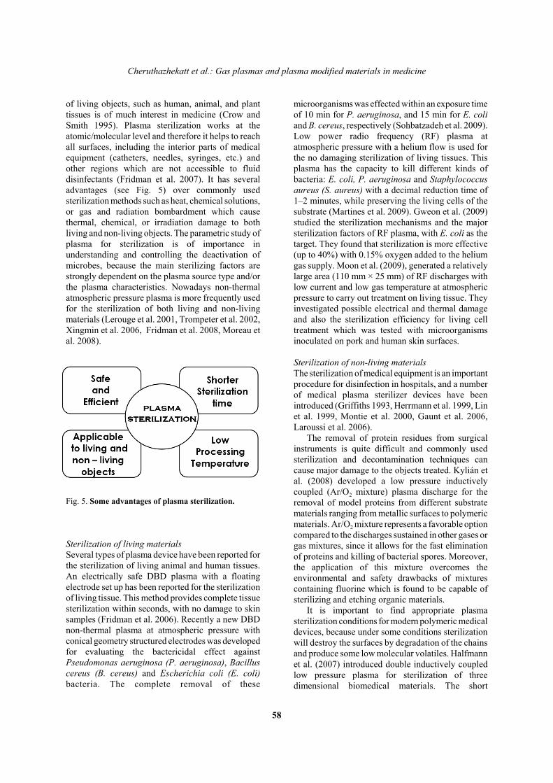
2.4 Aplikace
Byla testovana rada moznych aplikacı. Vsechny uvedene aplikace jsou pro variantuDBD tryskoveho vyboje. Jednou z nich je zmena povrchove energie povrchu opra-covaneho substratu. Byly testovany ruzne typy substratu napr. sklo, plasty, kovy,po kratke expozicnı jednotky sekund se povrch stava podstatne hydrofilnejsı, vesrovnanı s neopracovanym povrchem. Tato zmena povrchovych vlastnostı nenı tr-vala a podle druhu substratu mizı v radu radu jednotek hodin pro kovy az dnupro plasty. Dalsı zajımavou aplikacı je depozice tenkych vrstev za atmosferickehotlaku [3] . Do proudu pracovnıho plynu argonu se pridavajı pary HMDSO - Hexam-ethyldisiloxanu a vytvarı se tenka vrstva, ktera zatım nema prılis dobre mechanickevlastnosti, ale za urcitych parametru vyboje a geometrickeho usporadanı je moznepripravit vrstvu, ktera je ultrahydrofobnı [4]. Efekt dopadu kapky vody na ultra-hydrofobnı vrstvu byl nameren pomocı rychle opticke kamery zapujcene z VUT vBrne.
Ve spolupraci s analytickou chemiı je testovana moznost vyuzitı tohoto typuvyboje pro chemicke analyzy. Do proudu pracovnıho plynu argonu se definovanymzpusobem pridava aerosol roztoku s ruznou koncentracı nejakeho prvku a pomocıoptickeho spektrometru se sleduje stabilita a zmena relativnı intenzity vybranychanalytickych spektralnıch car. Dosazene vysledky zatım nebyly publikovany.
V soucasne dobe se intenzivne zkoumajı moznosti vyuzitı plazmatu v biome-dicınskych aplikacıch [5]. Ve spolupraci s mikrobiology byla studovana moznoststerilizace teplotne citlivych materialu pomocı plazmove trysky. Bylo testovanonekolik druhu mikroorganizmu a vliv vykonu a expozicnı doby na jejich prezitı, byloovereno, ze dominantnım sterilizacnım efektem nenı UV zarenı generovane vybojem,ale prıme pusobenı vyboje na mikroorganismy. Ve spolupraci s plastickou chirurgiıbyla testovana moznost vyuzitı plazmove tuzka jako chirurgickeho nastroje, jakoplazmovy skalpel. Dosazene vysledky ukazujı moznost rezanı i koagulace pomocıplazmove tuzky, ale pri porovnanı se stavajıcımi plazmovymi systemy, ktere se vchirurgii jiz vyuzıvajı a majı vsechny potrebne atesty, nenı tento aplikacnı smer proplazmovou tuzku prılis perspektivnı.
Jednou z nevyhod plazmove trysky je mala plocha substratu, kterou je mozneopracovat jednou tryskou. Resenım je pohybovat tryskou, nebo substratem naprıkladpomocı nejakeho manipulatoru, nebo sestavenı zarızenı z nekolika trysek.
7
3 Barierove vyboje, jako zdroje UV - zarenı
3.1 Uvod
Intenzivnı a levne zdroje UV zarenı jsou velmi zajımave pro radu aplikacı, napr.modifikace povrchu, fotokatalyticke reakce, sterilizace povrchu a kapalin, nebo jakoprimarnı zdroj pro buzenı luminoforu v osvetlovacı technice. Nejrozsırenejsım zdro-jem UV zarenı je v soucasne dobe nızkotlaky vyboj v parach rtuti, kde domi-nantnı spektralnı cara v UV oblasti ma vlnovou delku 253.65 nm. Probıha intenzivnıvyzkum UV zdroju zarenı zalozenych na barierovych vybojıch v excimernıch smesıchplynu na bazi halogennıch prvku Cl, F, I. Cılem je zıskat levny a intenzivnı zdrojUV zarenı s velkou zivotnosti a dobrou ucinnostı premeny elektricke energie na UVzarenı.
3.2 Experimentalnı usporadanı
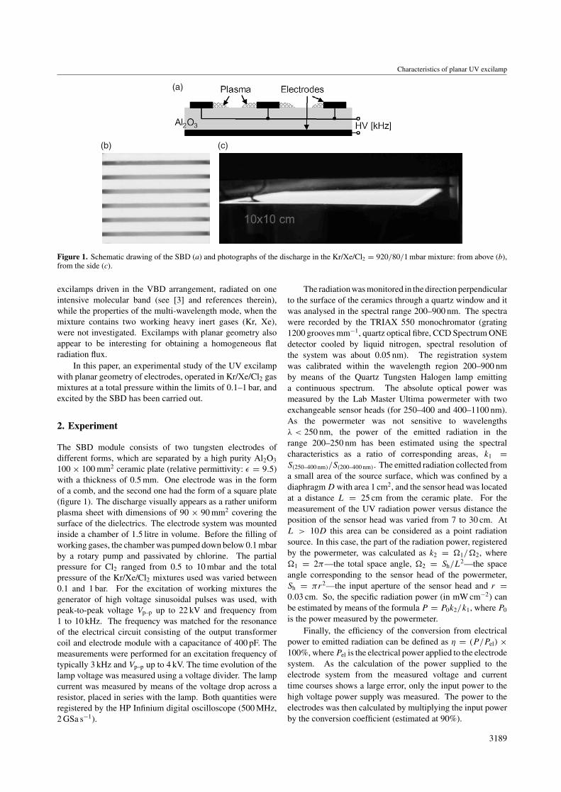
Existujı dve zakladnı konfigurace excimernıch barierovych vyboju. Prvnı je uspora-danı s objemovym barierovym vybojem, kde jedna, nebo dve oddelene elektrody jsoupokryty dielektrickou vrstvou napr. dve rovnobezne desky, nebo valcove - koaxialnıusporadanı. Druhou variantu predstavuje povrchovy barierovy vyboj, kdy je destickadielektrika pokryta na jedne strane systemem vodivych pasku a na druhe strane jedielektrikum pokoveno. Na nasem pracovisti jsme zkoumali obe varianty, komen-tovane clanky jsou zamereny pouze na povrchovy barierovy vyboj [6], [7]. Jakopracovnı plyny byly pouzity excimernı smesy plynu He-Kr-Xe-Cl2 a He-Kr-Xe-I sruznym pomerem jednotlivych slozek a celkovym tlakem 100-1000 hPa. Jako dielek-trikum byla pouzita korundova desticka Al2O3 s rozmery 100x100 mm, s tloust’kou0.5 mm. Jako napajecı zdroj byl pouzit nızkofrekvencnı generator s frekvencı 1-100 kHz a maximalnı amplitudou napetı 11 kV.
3.3 Diagnostika a aplikace
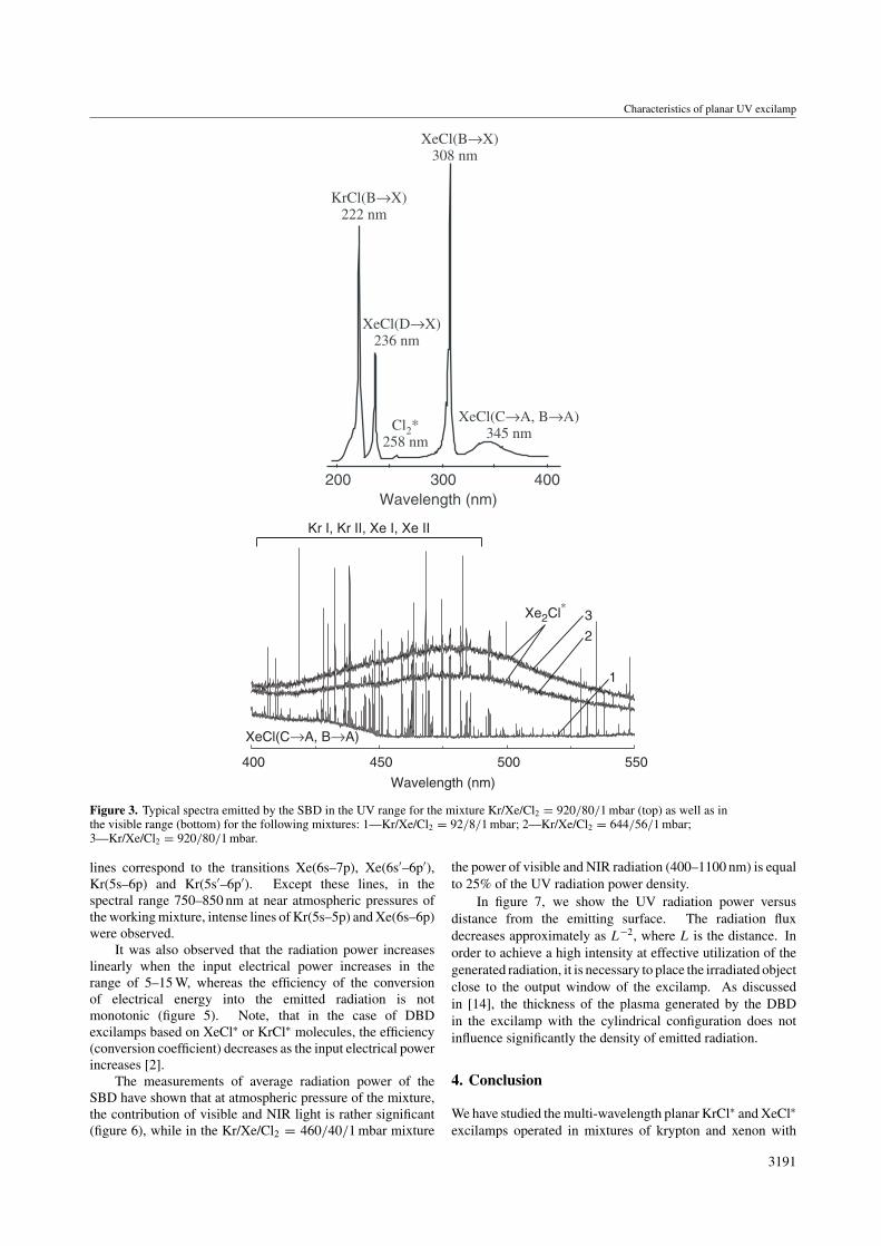
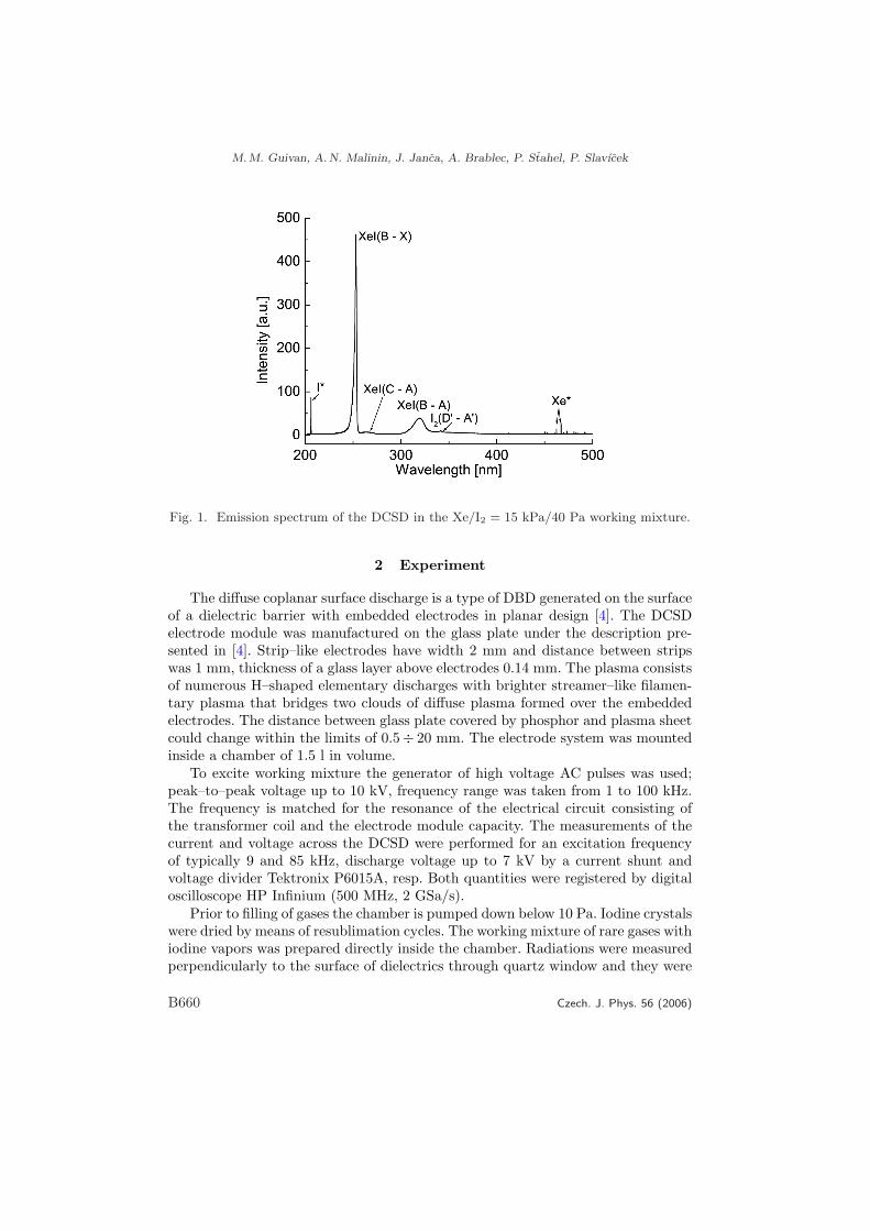
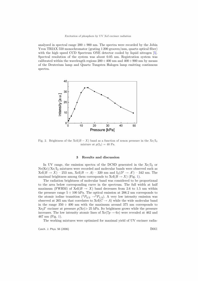
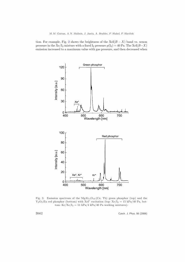
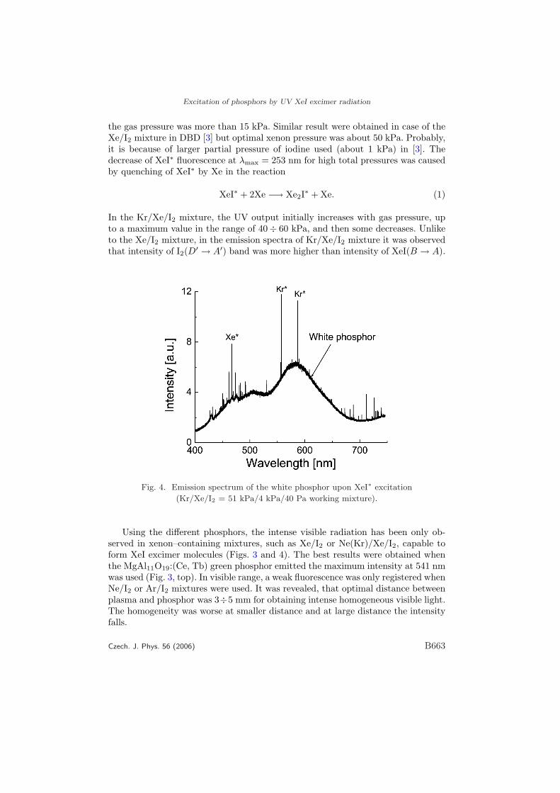
Jako zakladnı diagnosticka metoda byla pouzita opticka emisnı spektrometrie voblasti vlnovych delek 200-1000 nm. V UV oblasti byly namereny nasledujıcı ex-cimernı molekulove pasy pro smes Kr-Xe-Cl2 [6]: 222 nm - KrCl, 236 nm XeCl,258 nm - Cl2, 308 nm - XeCl, 345 nm - XeCl a pro smes Kr-Xe-I [7]: 253 nm - XeI,320 nm - XeI, 342 nm - I2. Pro smes Kr-Xe-Cl2 mel nejvetsı intenzitu pas 308 nm -XeCl, pro smes Kr-Xe-I mel nejvetsı intenzitu pas 253 nm - XeI.
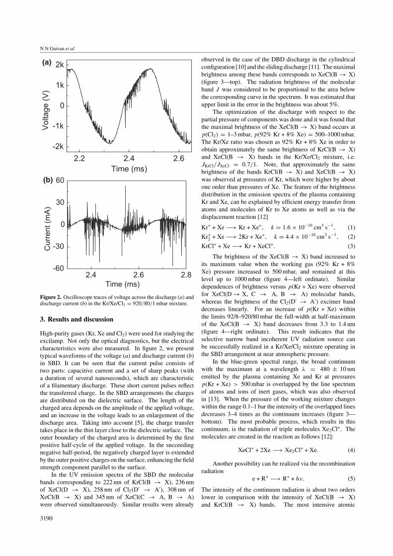
Krome opticke emisnı spektrometrie byly monitorovany elektricke parametrybarierovych vyboju pomocı osciloskopu a napet’ovych a proudovych sond. Pro odhaducinnosti premeny elektricke energie na UV zarenı byl meren celkovy vyzarenysvetelny vykon v UV-VIS-NIR oblasti vlnovych delek.
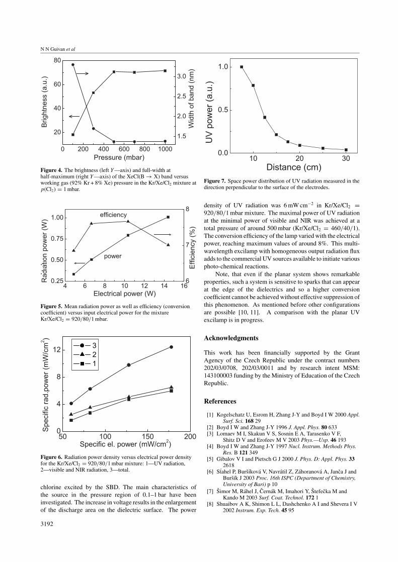
Ve smesi Kr-Xe-Cl2 = 920-80-1 hPa byla dosazena hustota vykonu UV zarenı6 mWcm−2, zatımco maximalnı potlacenı podılu viditelneho a infracerveneho (NIR)zarenı byla nalezena pri celkovem tlaku 500 hPa(Kr-Xe-Cl2 = 460-40-1 hPa).
Z moznych aplikacı barierovych vyboju v excimernıch smesıch byla na nasempracovisti zkoumana moznost buzenı luminoforu v osvetlovacı technice [7].
8
4 Diafragmovy vyboj v kapaline
4.1 Uvod
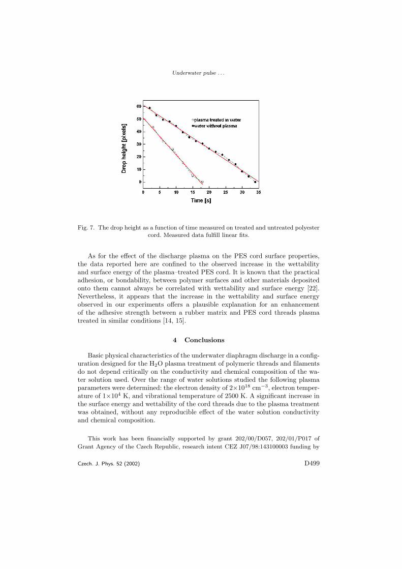
Plazmova uprava povrchovych vlastnostı materialu se v poslednı dobe velmi in-tenzivne studuje. Jedou ze zkoumanych variant je vyuzitı diafragmovych vybojuv kapalinach. Clanek [8] se zabyva diagnostikou a aplikacı diafragmoveho vybojena opracovanı polyesterovych vlaken a clanek [9] na opracovanı polypropylenovychnetkanych textiliı.
4.2 Experimentalnı usporadanı
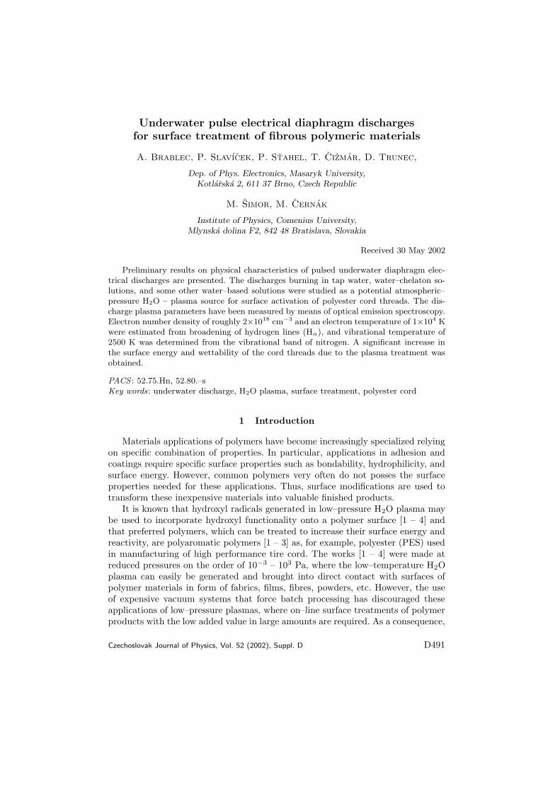
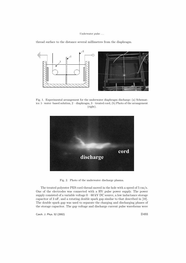
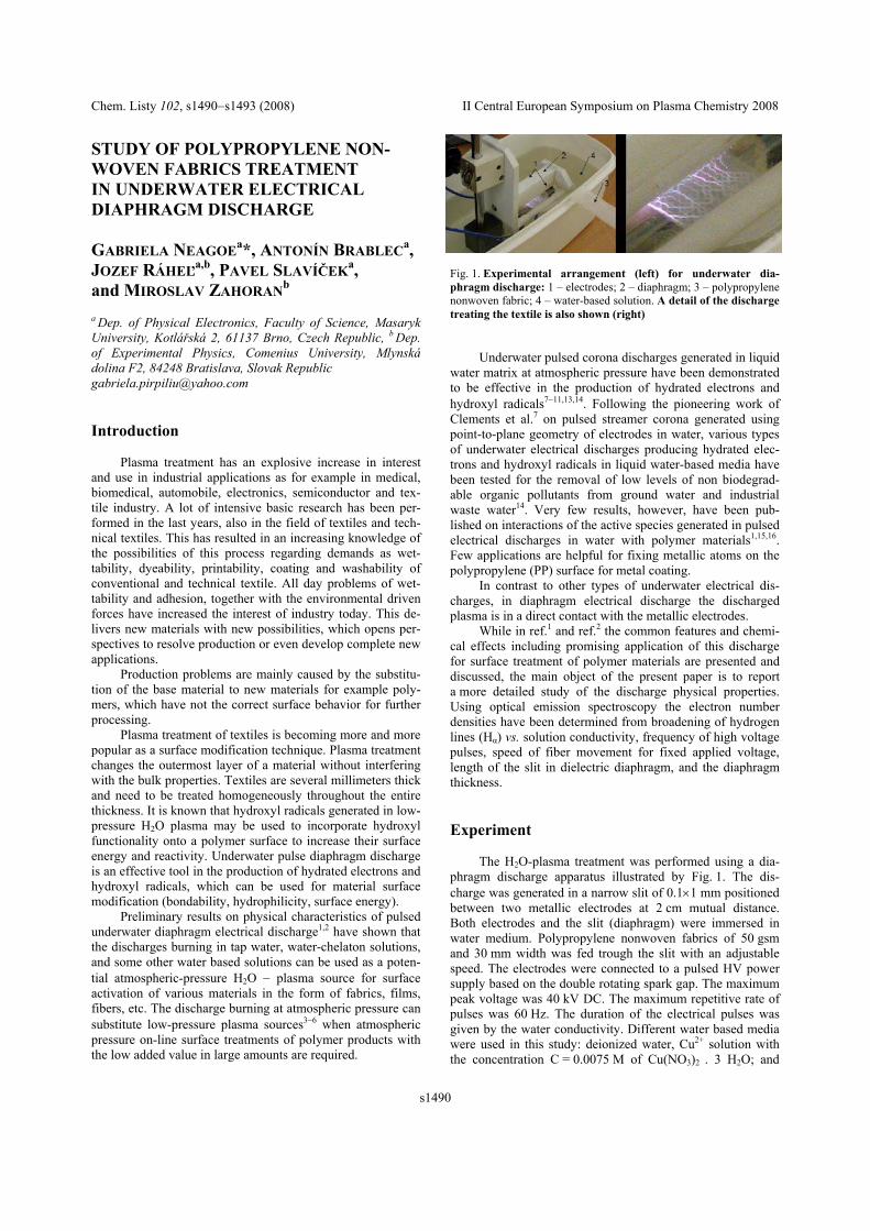
Zakladnı konfigurace diafragmoveho vyboje je nadoba s kapalinou rozdelena pre-pazkou s malym kruhovym otvorem na dve casti a v kazde casti je jedna kovovaelektroda spojena s vysokonapet’ovym generatorem. Vyboj horı v otvoru v prepazce.Tato varianta se hodı na opracovanı vlaken, ktera jsou protahovana tımto otvorem vprepazce. Dalsı mozna konfigurace je mısto kruhoveho otvoru pouzıt uzkou sterbinu.Tato konfigurace je vhodna i pro opracovanı tenkych plosnych materialu. Pri nasichexperimentech byl pouzıvan kruhovy otvor s prumerem 1.2 mm v prepazce s tloust’kou3 mm a sterbina s sırkou 1 mm. Elektrody byly napajeny z vysokonapet’ovehopulznıho generatoru postaveneho na principu rotujıcıho jiskriste s maximalnı am-plitudou 60 kV a maximalnı opakovacı frekvencı 60 Hz. Rychlost prevıjenı polyes-terovych vlaken byla 5 cm/s.
4.3 Diagnostika a aplikace
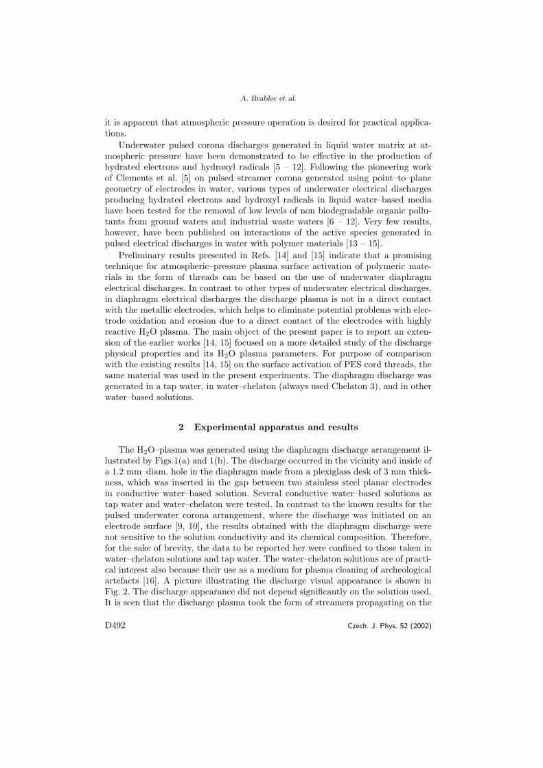
Vyboj vznika vlivem velke proudove hustoty v mıste, kde je otvor, nebo sterbina vprepazce. Velky vliv na parametry vyboji i opracovanı ma pouzita pracovnı kapalina,zejmena jejı elektricka vodivost. V prıpade opracovanı vlaken, nebo netkanych tex-tiliı hraje roli i plyn sorbovany na povrchu tohoto materialu a plyn v porech tohotomaterialu.
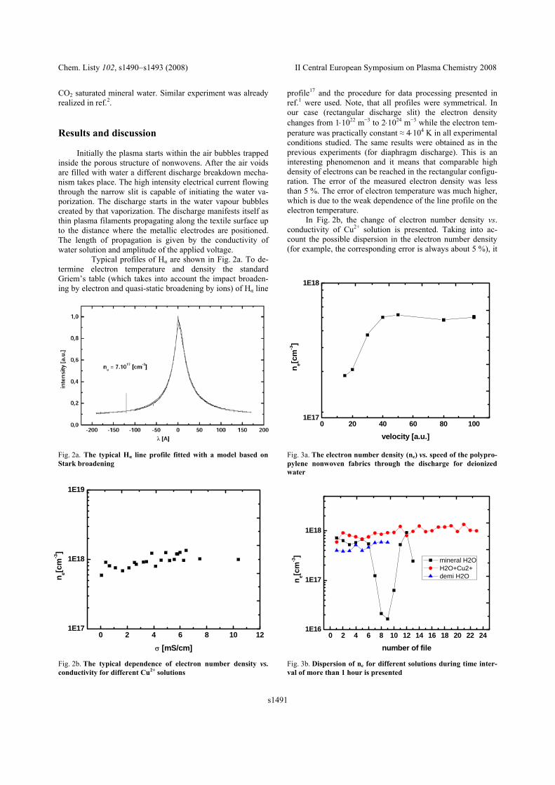
Pro urcovanı zakladnıch parametru diafragmovych vyboju byla pouzita optickeemisnı spektroskopie. Dominantnı ve spektrech byly vodıkove cary Hα a Hβ. Zrozsırenı techto car byla urcena koncentrace elektronu, ktera se pohybovala v rozsahu1×1022−2×1024 m−3, podle toho jak se menily parametry - druh kapaliny, vodivostkapaliny, rychlost pohybu vlakna, nebo textilie [8], [9].
Elektricke parametry diafragmovych vyboju byly mereny pomocı osciloskopu avysokonapet’ove sondy a kapacitnıho delice a proudove sondy.
Diafragmove vyboje poskytujı unikatnı system, v kterem mohou vzajemne inter-agovat pevny substrat, kapalina a plazma. Tyto vyboje mohou byt pouzity naprıkladk cistenı odpadnıch vod, zmene povrchovych vlastnostı polymernıch materialu, krozkladu, nebo synteze chemickych latek, nebo k nanasenı nanocastic na ruzne ma-terialy.
9
5 Koplanarnı povrchovy vyboj - DCSBD
5.1 Uvod
Pracovnı skupinou prof. M.Cernaka byl na Masarykove univerzite v Brne a Komens-keho univerzite v Bratislave vyvinut plosny plazmovy zdroj - difuznı koplanarnıpovrchovy barierovy vyboj (Diffuse Coplanar Surface Barrier Discharge - DCSBD).Tento vyboj pracuje za atmosferickeho tlaku prakticky v libovolnem plynu - vzduch,N2, O2, Ar, ....
Vyvoj tohoto systemu pokracuje dal a cılem je v ramci projektu CZ.1.05/2.1.00-/03.0086 - ”Regionalnı VaV centrum pro nızkonakladove plazmove a nanotechnolog-icke povrchove upravy”a navazujıcıch projektu, jeho vyuzitı v ruznych prumyslovychaplikacıch zejmena k povrchove uprave plosnych substratu.
5.2 Konstrukcnı resenı
Konstrukce DCSBD vybojky je tvorena systemem kovovych elektrod ve tvaru paskus delkou asi 150 mm a sırkou 0.5 mm v korundove (Al2O3) keramice. Plazma horına povrchu teto korundove keramiky a elektrod se vubec nedotyka, tım je zajistenadlouha zivotnost vybojky, protoze nedochazı k rozprasovanı elektrod vlivem vyboje,ani k oteru elektrod vlivem pohybu substratu ve vyboji, plazma i substrat je vkontaktu pouze s korundovou keramikou. K napajenı tohoto vyboje se pouzıvanızkofrekvencnı vysokonapet’ovy generator s pracovnı frekvencı 1-20 kHz a am-plitudou napetı asi 10 kV [10]. Dıky ucinnemu olejovemu chlazenı dosahuje tatoDCSBD vybojka plosne vykonove hustoty az 5 Wcm−2. Probıha optimalizace ge-ometrickych rozmeru elektrod, tloust’ky keramicke desticky a frekvence a vykonvysokonapet’oveho generatoru s cılem zlepsit provoznı vlastnosti vybojky, tepelnouodolnost prodlouzit jejı zivotnost a zvetsit jejı ucinnost.
5.3 Diagnostika
Elektricke parametry DCSBD vyboje byly monitorovany pomocı osciloskopu, vysoko-napet’ove sondy s delıcım pomerem 1:1000, proudove sondy a merice vykonu nızko-frekvencnıho vysokonapet’oveho generatoru. Typicky vykon je 400 W a amplitudanapetı 10 kV.
Dalsı diagnostickou metodou byla opticka emisnı spektrometrie ve vlnove oblasti200 - 1000 nm. Pro vyboj ve vzduchu byly v emisnım spektru namereny spektralnıcary kyslıku a molekulove pasy dusıku (druhy pozitivnı system) a v UV oblastimolekulovy pas OH. Z pomeru relativnıch intenzit rotacnıch car OH byla urcenarotacnı teplota asi 400 K a z pomeru intenzit vibracnıch pasu druheho pozitivnıhosystemu dusıku vibracnı teplota asi 2000 K, takze se jedna o nızkoteplotnı neizoter-micke plazma.
Pro vyhodnocenı ucinku DCSBD vyboje na opracovavane materialy se pouzıvajıstandardnı metody pro analyzu povrchu, jako meric kontaktnıho uhlu a povrchoveenergie, mikroskopy opticke, SEM, AFM, nebo diagnosticke metody MALDI-TOF,FTIR, XPS. Krome techto beznych univerzalnıch diagnostickych metod se pro kon-
10
kretnı aplikace pouzıvajı specialnı jednoucelove metody, napr. pri uprave zivocisnychvlaken test zplst’ovanı.
5.4 Aplikace
DCSBD vyboj se zkouma, nejen pro sve zajımave fyzikalnı vlastnosti, ale i prokonkretnı prumyslove aplikace. Je vhodny zejmena pro povrchovou upravu lacinychplosnych materialu, jako papır, netkane textilie, kovove folie, sklo. K moznym povr-chovym upravam patrı zejmena zmena povrchove energie, cistenı povrchu, nebozmena drsnosti povrchu. Vyhodou DCSBD vybojek, dıky jejich malym rozmeruma nenarocnemu provozu, je moznost provadet testy prımo na vyrobnıch linkachnasich prumyslovych partneru. Jednım z nich je naprıklad firma Pegas a.s. vyznamnyvyrobce netkanych textiliı.
Jednou z poslednıch aplikacı, ktera byla vyzkousena ve spolupraci s firmou Tonaka.s.v Novem Jicıne, je uprava zivocisnych vlaken za ucelem zlepsenı jejich plstıcıchvlastnostı. V soucasne dobe se provadı uprava zivocisnych vlaken pred zplst’ovanımpomocı chemickych metod zalozenych na vyuzitı roztoku kyselin HCl, HNO3, H3PO4
a H2SO4. Pokud se podarı nahradit tento chemicky postup plazmovou upravou, budeto mıt vyznamne ekologicke i ekonomicke vyhody.
11
6 Seznam clanku
Reference
[1] Janca J., Klima M., Slavicek P., Zajickova L., HF plasma pencil - new sourcefor plasma surface processing, SURFACE & COATINGS TECHNOLOGY Vol-ume: 116 Pages: 547-551 Published: SEP 1999
[2] Kapicka V., Sicha M., Klima M., Hubicka Z., Tous J., Brablec A., Slavicek P.,Behnke JF., Tichy M., Vaculik R., The high pressure torch discharge plasmasource, PLASMA SOURCES SCIENCE & TECHNOLOGY Volume: 8 Issue:1 Pages: 15-21 Published: FEB 1999
[3] Slavicek P., Bursikova V., Brablec A., Kapicka V., Klima M., Deposition ofpolymer films by rf discharge at atmospheric pressure, CZECHOSLOVAKJOURNAL OF PHYSICS Volume: 54 Pages: C586-C591 Part: Part 4 Pub-lished: 2004
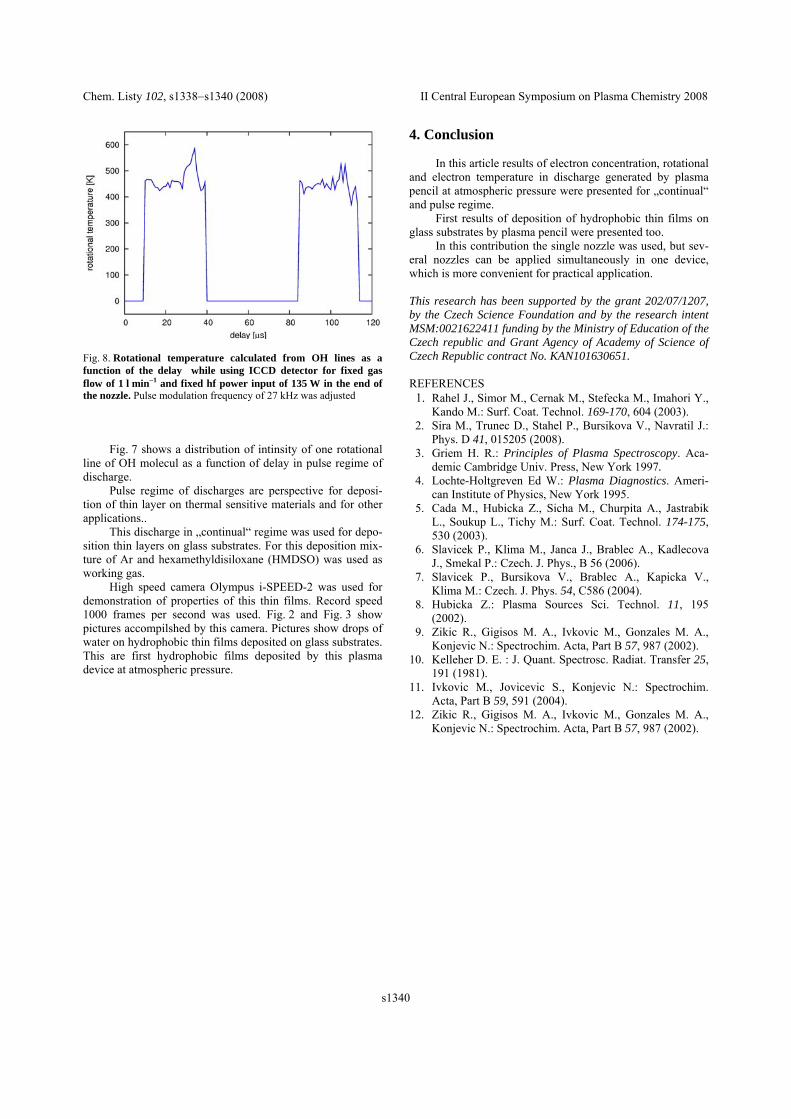
[4] Slavıcek, P.,Klıma, M.,Skacelova, D.,Kedronova, E.,Brablec, A.,Aubrecht, V.RF discharge at atmospheric pressure - diagnostics and applications. Chemickelisty, 102, 16, od s. 1338-1340, 3 s. ISSN 1803-2389. 2008
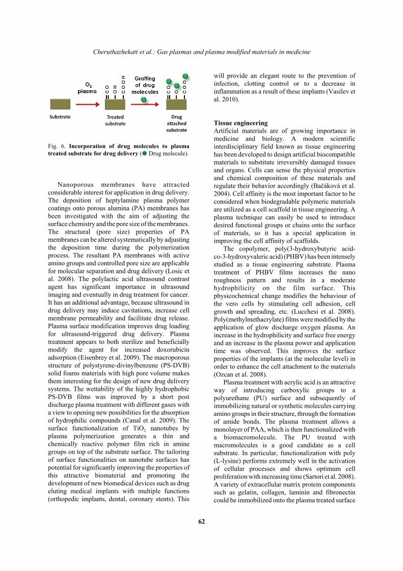
[5] Cheruthazhekatt S., Cernak M., Slavicek P., Havel J., Gas plasmas and plasmamodified materials in medicine, JOURNAL OF APPLIED BIOMEDICINEVolume: 8 Issue: 2 Pages: 55-66 Published: JUN 2010
[6] Guivan NN., Janca J., Brablec A., Stahel P., Slavicek P., Shimon LL., PlanarUV excilamp excited by a surface barrier discharge, JOURNAL OF PHYSICSD-APPLIED PHYSICS Volume: 38 Issue: 17 Pages: 3188-3193 Published: SEP7, 2005
[7] Guivan M. M., Malinin A. N., Brablec A., Janca J., Stahel P., SlavicekP.,Excitation of phosphors by UV XeI excimer radiatio, CZECHOSLOVAKJOURNAL OF PHYSICS Volume: 56 Pages: B659-B664 Part: Part 4 Suppl.B Supplement: Part 4 Suppl. B Published: 2006
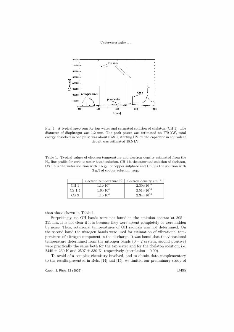
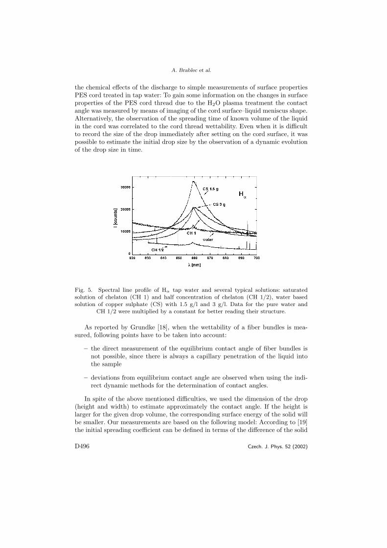
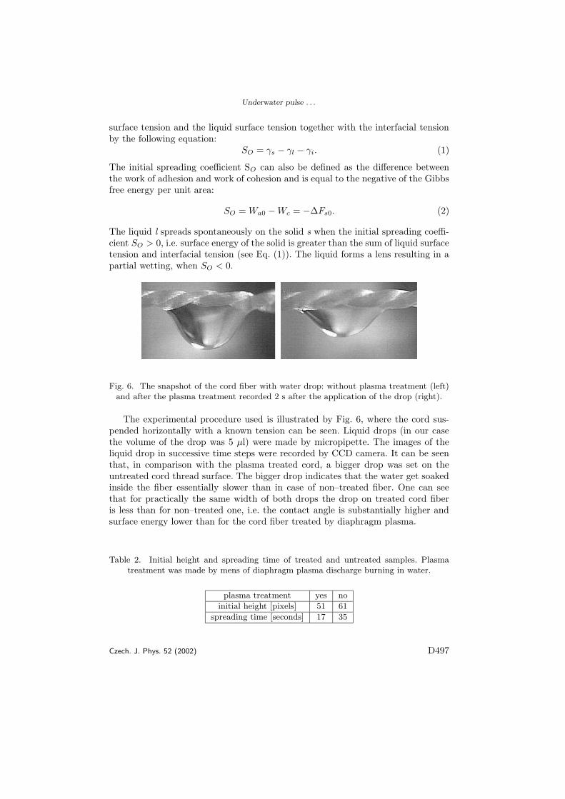
[8] Brablec A., Slavicek P., Stahel P., Cizmar T., Trunec D., Simor M., CernakM., Underwater pulse electrical diaphragm discharges for surface treatmentof fibrous polymeric materials, CZECHOSLOVAK JOURNAL OF PHYSICSVolume: 52 Pages: 491-500 Supplement: Suppl. D Published: 2002
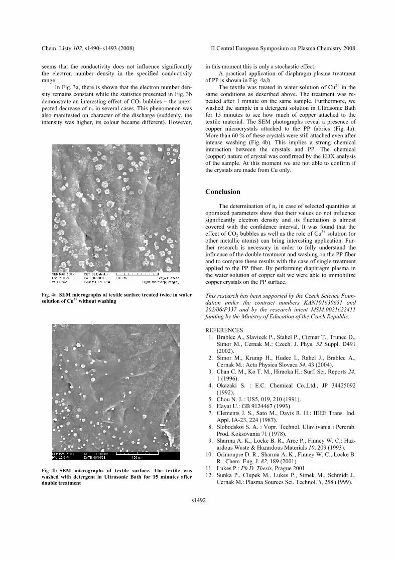
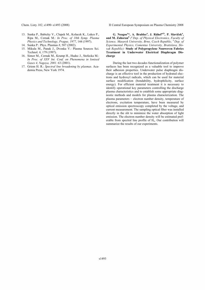
[9] Neagoe, G.,Brablec, A.,Rahel’, J.,Slavıcek, P.,Zahoran, M. Study of Polypropy-lene Nonwoven Fabrics Treatment in Underwater Electrical Diaphragm Dis-charge. Chemicke listy, 2008, 102, od s. 1490-1493, 4 s. ISSN 0009-2770. 2008
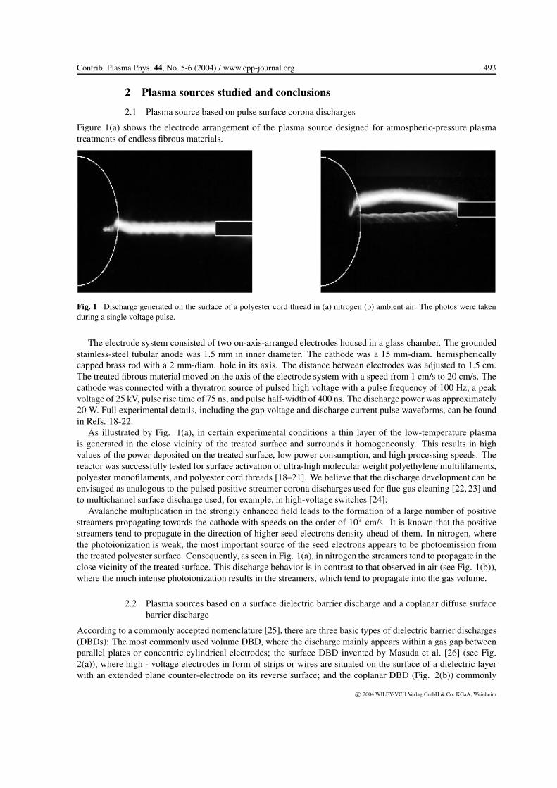
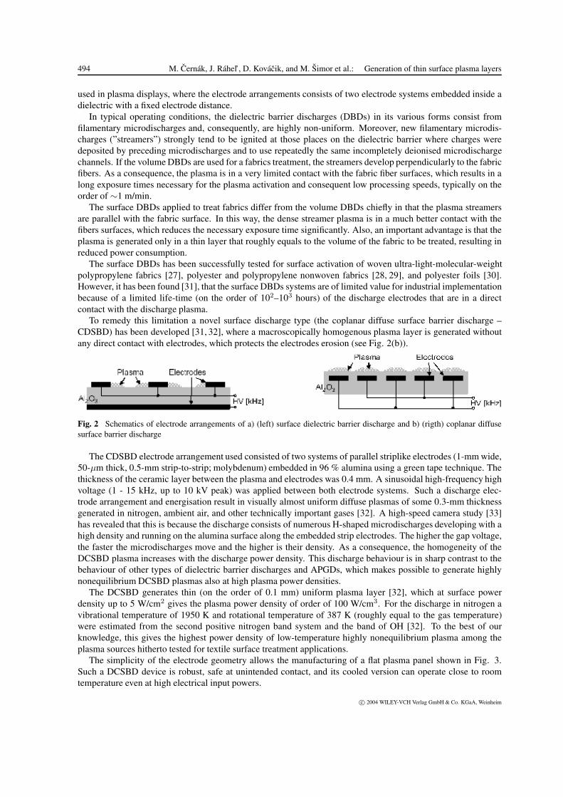
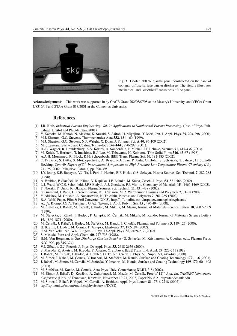
[10] Cernak M., Rahel J., Kovacik D., Simor M., Brablec A., Slavicek P., Genera-tion of thin surface plasma layers for atmospheric-pressure surface treatments,CONTRIBUTIONS TO PLASMA PHYSICS Volume: 44 Issue: 5-6 Pages:492-495 Published: 2004
12
Surface and Coatings Technology 116–119 (1999) 547–551www.elsevier.nl/locate/surfcoat
HF plasma pencil — new source for plasma surface processing
J. Janca*, M. Klıma, P. Slavıcek, L. ZajıckovaDepartment of Physical Electronics, Faculty of Science, Masaryk University, Kotlaoska 2, 61137 Brno, Czech Republic
1. Introduction of these measurements have produced a comparativelyunified idea of the parameters of this kind of hf dischargeplasma. The possibility of hf generation of the hollowThe unipolar high-frequency (hf ) discharges have
been used as a plasma source of a non-isothermal plasma cathode plasma jet at atmospheric pressure brings aboutan extension of technological abilities of high-pressurethat can be excited in a wide range of pressures. The
degree of non-isothermicity depends on the supplied discharges.power output, the working gas, and the pressure atwhich the discharge is excited [1,2]. Recently, the unipo-lar hf discharges were combined with a hollow cathode, 2. Experimentalwhich acts simultaneously as a nozzle for a working gasinlet [3,4]. The hollow cathode represents a very effective The core of our experiment was an extension piecesource of the gas discharge plasma. Its geometry pro- made of a pencil-shaped dielectric with a built-in specialmotes oscillations of hot electrons inside the cathode, hollow electrode. The powered electrode consists of athereby enhancing ionization and ion bombardment of thin pipe with an inner diameter of 1–2 mm and a lengthinner walls, and influencing other subsequent processes. of several centimetres. The hollow electrode was con-At the same power, the hollow cathode exhibits a plasma nected with a cable with the matching network of thedensity 1-2 orders higher than with conventional 13.56 MHz power supply and adapted like a currentelectrode systems [5]. Up to now, the unipolar hf plasma hand-operated tool. The power absorbed in the plasmareactor systems with hollow cathode electrodes have pencil was adjusted in such manner that the torchbeen applied at low pressures only (up to 2 kPa). Dense discharge was created at the electrode edge. As an activechemically reactive plasmas produced by hollow cathode medium flowing through the hollow electrode of theunipolar hf discharges can also be favourably used for plasma pencil gas, a liquid or a mixture of disperseddifferent plasma-processing technologies. particles (powders) was used. If liquid is used as the
Diagnostics of unipolar and bipolar hf discharges working medium, the second (earthed) electrode must(without hollow electrode) excited at atmospheric and be used, and the discharge is excited as a hf torch arc.subatmospheric pressures were frequently carried out in Schematic diagrams of two possible experimentalthe 1960s and 1970s using various spectral, microwave arrangements employed in the present study are shownand calorimetric diagnostic methods [6,7]. The results in Figs. 1 and 2. The supplied power ranged from 20 to
200 W, and the hf amplitude voltage ranged from 100* Corresponding author. to 1000 V. In studying optical emission, we found that
548 J. Janca et al. / Surface and Coatings Technology 116–119 (1999) 547–551
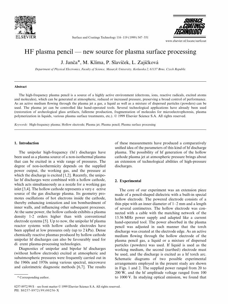
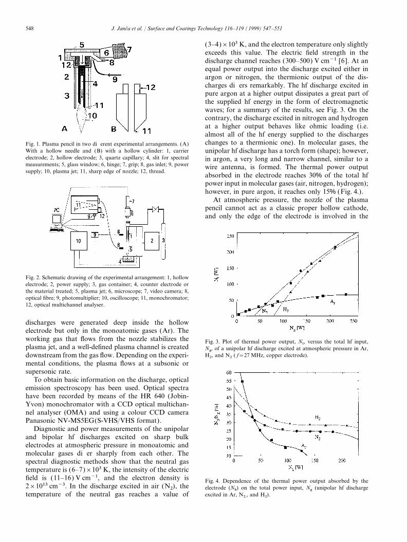
(3–4)×103 K, and the electron temperature only slightlyexceeds this value. The electric field strength in thedischarge channel reaches (300–500) V cm−1 [6 ]. At anequal power output into the discharge excited either inargon or nitrogen, the thermionic output of the dis-charges differs remarkably. The hf discharge excited inpure argon at a higher output dissipates a great part ofthe supplied hf energy in the form of electromagneticwaves; for a summary of the results, see Fig. 3. On thecontrary, the discharge excited in nitrogen and hydrogenat a higher output behaves like ohmic loading (i.e.almost all of the hf energy supplied to the dischargeschanges to a thermionic one). In molecular gases, theFig. 1. Plasma pencil in two different experimental arrangements. (A)
With a hollow needle and (B) with a hollow cylinder: 1, carrier unipolar hf discharge has a torch form (shape); however,electrode; 2, hollow electrode; 3, quartz capillary; 4, slit for spectral in argon, a very long and narrow channel, similar to ameasurements; 5, glass window; 6, hinge; 7, grip; 8, gas inlet; 9, power wire antenna, is formed. The thermal power outputsupply; 10, plasma jet; 11, sharp edge of nozzle; 12, thread.
absorbed in the electrode reaches 30% of the total hfpower input in molecular gases (air, nitrogen, hydrogen);however, in pure argon, it reaches only 15% (Fig. 4.).
At atmospheric pressure, the nozzle of the plasmapencil cannot act as a classic proper hollow cathode,and only the edge of the electrode is involved in the
Fig. 2. Schematic drawing of the experimental arrangement: 1, hollowelectrode; 2, power supply; 3, gas container; 4, counter electrode orthe material treated; 5, plasma jet; 6, microscope; 7, video camera; 8,optical fibre; 9, photomultiplier; 10, oscilloscope; 11, monochromator;12, optical multichannel analyser.
discharges were generated deep inside the hollowelectrode but only in the monoatomic gases (Ar). Theworking gas that flows from the nozzle stabilizes the Fig. 3. Plot of thermal power output, Nt, versus the total hf input,plasma jet, and a well-defined plasma channel is created Ng, of a unipolar hf discharge excited at atmospheric pressure in Ar,
H2, and N2 ( f=27 MHz, copper electrode).downstream from the gas flow. Depending on the experi-mental conditions, the plasma flows at a subsonic orsupersonic rate.
To obtain basic information on the discharge, opticalemission spectroscopy has been used. Optical spectrahave been recorded by means of the HR 640 (Jobin-Yvon) monochromator with a CCD optical multichan-nel analyser (OMA) and using a colour CCD cameraPanasonic NV-MS5EG(S-VHS/VHS format).
Diagnostic and power measurements of the unipolarand bipolar hf discharges excited on sharp bulkelectrodes at atmospheric pressure in monoatomic andmolecular gases differ sharply from each other. Thespectral diagnostic methods show that the neutral gastemperature is (6–7)×103 K, the intensity of the electricfield is (11–16) V cm−1, and the electron density is Fig. 4. Dependence of the thermal power output absorbed by the2×1013 cm−3. In the discharge excited in air (N2), the electrode (Nb) on the total power input, Ng (unipolar hf discharge
excited in Ar, N2,, and H2).temperature of the neutral gas reaches a value of
549J. Janca et al. / Surface and Coatings Technology 116–119 (1999) 547–551
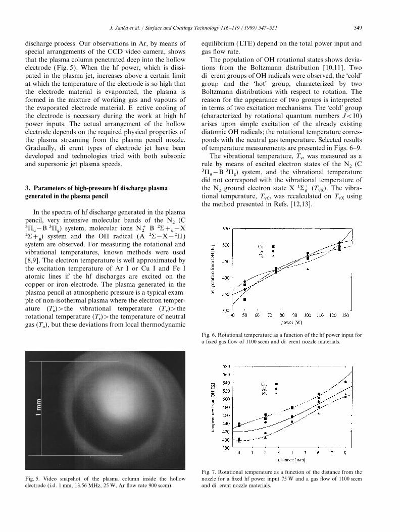
discharge process. Our observations in Ar, by means of equilibrium (LTE) depend on the total power input andgas flow rate.special arrangements of the CCD video camera, shows
that the plasma column penetrated deep into the hollow The population of OH rotational states shows devia-tions from the Boltzmann distribution [10,11]. Twoelectrode (Fig. 5). When the hf power, which is dissi-
pated in the plasma jet, increases above a certain limit different groups of OH radicals were observed, the ‘cold’group and the ‘hot’ group, characterized by twoat which the temperature of the electrode is so high that
the electrode material is evaporated, the plasma is Boltzmann distributions with respect to rotation. Thereason for the appearance of two groups is interpretedformed in the mixture of working gas and vapours of
the evaporated electrode material. Effective cooling of in terms of two excitation mechanisms. The ‘cold’ group(characterized by rotational quantum numbers J<10)the electrode is necessary during the work at high hf
power inputs. The actual arrangement of the hollow arises upon simple excitation of the already existingdiatomic OH radicals; the rotational temperature corres-electrode depends on the required physical properties of
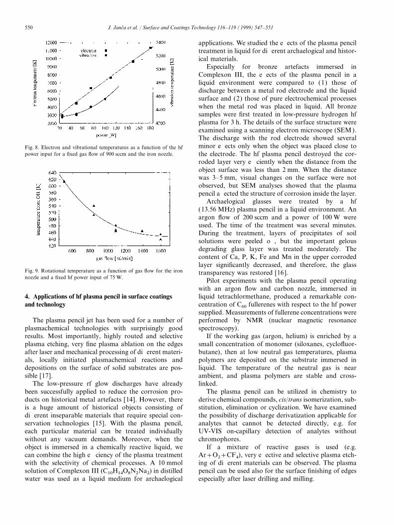
the plasma streaming from the plasma pencil nozzle. ponds with the neutral gas temperature. Selected resultsof temperature measurements are presented in Figs. 6–9.Gradually, different types of electrode jet have been
developed and technologies tried with both subsonic The vibrational temperature, Tv, was measured as arule by means of excited electron states of the N2 (Cand supersonic jet plasma speeds.3Pu−B 3Pg) system, and the vibrational temperaturedid not correspond with the vibrational temperature ofthe N2 ground electron state X 1S+
g(TvX). The vibra-3. Parameters of high-pressure hf discharge plasma
generated in the plasma pencil tional temperature, TvC, was recalculated on TvX usingthe method presented in Refs. [12,13].
In the spectra of hf discharge generated in the plasmapencil, very intensive molecular bands of the N2 (C3Pu−B 3Pg) system, molecular ions N+
2B 2S+u−X
2S+g) system and the OH radical (A 2S−X−2P )system are observed. For measuring the rotational andvibrational temperatures, known methods were used[8,9]. The electron temperature is well approximated bythe excitation temperature of Ar I or Cu I and Fe Iatomic lines if the hf discharges are excited on thecopper or iron electrode. The plasma generated in theplasma pencil at atmospheric pressure is a typical exam-ple of non-isothermal plasma where the electron temper-ature (Te)>the vibrational temperature (Tv)>therotational temperature (Tr)>the temperature of neutralgas (To), but these deviations from local thermodynamic
Fig. 6. Rotational temperature as a function of the hf power input fora fixed gas flow of 1100 sccm and different nozzle materials.
Fig. 7. Rotational temperature as a function of the distance from theFig. 5. Video snapshot of the plasma column inside the hollow nozzle for a fixed hf power input 75 W and a gas flow of 1100 sccm
and different nozzle materials.electrode (i.d. 1 mm, 13.56 MHz, 25 W, Ar flow rate 900 sccm).
550 J. Janca et al. / Surface and Coatings Technology 116–119 (1999) 547–551
applications. We studied the effects of the plasma penciltreatment in liquid for different archaelogical and histor-ical materials.
Especially for bronze artefacts immersed inComplexon III, the effects of the plasma pencil in aliquid environment were compared to (1) those ofdischarge between a metal rod electrode and the liquidsurface and (2) those of pure electrochemical processeswhen the metal rod was placed in liquid. All bronzesamples were first treated in low-pressure hydrogen hfplasma for 3 h. The details of the surface structure wereexamined using a scanning electron microscope (SEM).The discharge with the rod electrode showed severalminor effects only when the object was placed close toFig. 8. Electron and vibrational temperatures as a function of the hf
power input for a fixed gas flow of 900 sccm and the iron nozzle. the electrode. The hf plasma pencil destroyed the cor-roded layer very efficiently when the distance from theobject surface was less than 2 mm. When the distancewas 3–5 mm, visual changes on the surface were notobserved, but SEM analyses showed that the plasmapencil affected the structure of corrosion inside the layer.
Archaelogical glasses were treated by a hf(13.56 MHz) plasma pencil in a liquid environment. Anargon flow of 200 sccm and a power of 100 W wereused. The time of the treatment was several minutes.During the treatment, layers of precipitates of soilsolutions were peeled off, but the important gelousdegrading glass layer was treated moderately. Thecontent of Ca, P, K, Fe and Mn in the upper corrodedlayer significantly decreased, and therefore, the glass
Fig. 9. Rotational temperature as a function of gas flow for the iron transparency was restored [16 ].nozzle and a fixed hf power input of 75 W. Pilot experiments with the plasma pencil operating
with an argon flow and carbon nozzle, immersed inliquid tetrachlormethane, produced a remarkable con-4. Applications of hf plasma pencil in surface coatings
and technology centration of C60 fullerenes with respect to the hf powersupplied. Measurements of fullerene concentrations wereperformed by NMR (nuclear magnetic resonanceThe plasma pencil jet has been used for a number of
plasmachemical technologies with surprisingly good spectroscopy).If the working gas (argon, helium) is enriched by aresults. Most importantly, highly routed and selective
plasma etching, very fine plasma ablation on the edges small concentration of monomer (siloxanes, cyclofluor-butane), then at low neutral gas temperatures, plasmaafter laser and mechanical processing of different materi-
als, locally initiated plasmachemical reactions and polymers are deposited on the substrate immersed inliquid. The temperature of the neutral gas is neardepositions on the surface of solid substrates are pos-
sible [17]. ambient, and plasma polymers are stable and cross-linked.The low-pressure rf glow discharges have already
been successfully applied to reduce the corrosion pro- The plasma pencil can be utilized in chemistry toderive chemical compounds, cis/trans isomerization, sub-ducts on historical metal artefacts [14]. However, there
is a huge amount of historical objects consisting of stitution, elimination or cyclization. We have examinedthe possibility of discharge derivatization applicable fordifferent inseparable materials that require special con-
servation technologies [15]. With the plasma pencil, analytes that cannot be detected directly, e.g. forUV-VIS on-capillary detection of analytes withouteach particular material can be treated individually
without any vacuum demands. Moreover, when the chromophores.If a mixture of reactive gases is used (e.g.object is immersed in a chemically reactive liquid, we
can combine the high efficiency of the plasma treatment Ar+O2+CF4), very effective and selective plasma etch-ing of different materials can be observed. The plasmawith the selectivity of chemical processes. A 10 mmol
solution of Complexon III (C10H14O8N2Na2) in distilled pencil can be used also for the surface finishing of edgesespecially after laser drilling and milling.water was used as a liquid medium for archaelogical
551J. Janca et al. / Surface and Coatings Technology 116–119 (1999) 547–551
5. Conclusions References
The high-frequency plasma pencil and its broad range [1] M. Moisan, J. Pelletier, Microwave Excited Plasmas, Elsevier,Amsterdam, 1992.of applications are a unique instrument for interested
[2] V. Farsky, J. Janca, Beitrage aus der Plasmaphysik 8 (1968)workers which has not been expected and originally not129.planned. Gradually, six different types of the electrode
[3] L. Bardos, Proc. XXI. Int. Conf. Phenomena in Ionized Gases,jets have been developed and technologies tried with Part III, Bochum (1993) 98.both subsonic and supersonic jet plasma speeds. The [4] L. Soukup, V. Perina, L. Jastrabık, M. Sıcha, P. Pokorny,temperature of the neutral gas can be easily changed by R.J. Soukup, M. Novak, J. Zemek, Surf. Coat. Technol. 78
(1996) 280.the high-frequency power input and flow rate of the[5] C.M. Horwitz, Appl. Phys. Lett. 43 (1983) 977.working media. So far, no source of plasma exists that[6 ] J. Janca, Czech J. Phys. B 17 (1967) 761.would make literally ‘watchmaker’ work possible in the[7] U. Jecht, W. Kessler, Z. Phys. 178 (1964) 133.plasma processing of the sample details. Another advan-[8] W. Lochte-Holtgreven, Plasma Diagnostics, North-Holland,
tage of the plasma pencil is the possibility of working Amsterdam, 1968.in a free atmosphere, in a liquid, at a lowered or [9] R.H. Tourin, Spectroscopic Gas Temperature Measurement,increased pressure. Some technologies have already been Elsevier, Amsterdam, 1966.
[10] H. Meinel, L. Krauss, J. Quant. Spectr. Radiat. Transfer 9used in various applications (restoration of archaelogical(1969) 443.glass artifacts, fullerene production, fragmentation of
[11] D.R. Crosley, R.K. Lengel, J. Quant. Spectr. Radiat. Transfer 15molecules for microelectrophoresis, plasma polymeriza-(1975) 579.tion in liquids, plasma etching, etc.). The hf plasma
[12] M.Z. Novgorodov, V.N. Ochkin, N.N. Sobolev, J. Tech. Phys.pencil can be fastened in the dielectric holder and used 40 (1970) 12678 in Russian.as a hand-operated tool. [13] A.D. Kosoruchkina, E.S. Trekhov, J. Tech. Phys. 45 (1975) 1082
in Russian.[14] S. Veprek, Ch. Eckmann, J.T. Elmer, Plasma Chem. Plasma Pro-
cess. 8 (4) (1988) 455.Acknowledgements[15] M. Klima, L. Zajıckova, J. Jancva et al., Zeitschrift fur Sweizer-
ische Archeologie und Kunstgeschichte 54 (1997) 31–33.This work was supported by the Grant Agency of [16 ] A. Brablec, P. Slavıcek, M. Klıma, V. Kapicka, Proc. ICPIGthe Czech Republic, grant number 106/96/K245, and XXIII band I, Toulouse (1997) 128.the Grant Agency of the Czech Ministry of Education [17] M. Klıma, J. Janca, V. Kapicka, P. Slavıcek, P. Saul, Czech Patent
PV 147698, 1998.VS96084.
Plasma Sources Sci. Technol.8 (1999) 15–21. Printed in the UK PII: S0963-0252(99)98877-1
The high pressure torch dischargeplasma source
V Kapi cka†, M Sıcha‡, M Kl ıma†, Z Hubi cka‡, J Tou s‡,A Brablec †, P Slav ıcek†, J F Behnke §, M Tich y‡ and R Vacul´ık†
† Department of Physical Electronics, Faculty of Science, Masaryk University, Kotlarska 2,611 37 Brno, Czech Republic‡ Department of Electronics and Vacuum Physics, Faculty of Mathematics and Physics,Charles University, V Holesovickach 2, 180 00 Prague 8, Czech Republic§ Institute of Physics, Ernst-Moritz-Arndt University, Domstraße 10a, D-17487 Greifswald,Germany
Received 5 May 1997, in final form 3 August 1998
Abstract. We present a plasma source which works on the principle of the arc torchdischarge. The powered electrode of the arc torch discharge was made from a thin pipe thatsimultaneously acts as the nozzle through which the working gas flows to the dischargeregion. The flow of the working gas stabilizes the arc torch discharge and a well definedplasma channel is created. The advantage of this system is that it is able to work at highpressure of working gas up to atmospheric pressure inside the plasma-chemical reactor andalso in free space.
1. Introduction
Recently the RF low pressure plasma-chemical reactor withhollow cathode (radio-frequency plasma jet—RPJ) has beendeveloped for the plasma surface and coating technologies,treatments of various materials and thin film deposition [1–4].The primary RF discharge burning inside the reactor chamberinduces the additional discharge inside the hollow cathode.The working gas flows through the hollow cathode that actssimultaneously as an inlet nozzle for the working gas. Theincoming working gas forces the hollow cathode dischargesupersonically from the nozzle into the reactor and a welldefined plasma channel is created inside the primary RFplasma. This plasma channel can be used as a plasma sourcefor the surface treatment technology and in particular casesfulfils special requirements necessary for deposition of thinfilms on internal walls of cavities, holes and on substrates withcomplex shapes. Further, by means of the RPJ reactor thethin films with defined stoichiometry Ge3N4 [5] and Cu3N4
[6] have been achieved. However, this reactor requires arelatively low pressure of the working gas from several Pa toseveral tens of Pa.
Sometimes it is desirable to have at our disposal a plasmasource that generates at higher pressures a similar plasmachannel like the low pressure RF reactor with hollow cathode[1–4]. Possible examples are the surface treatment andconservation of archaeological ancient artefacts or the plasmasurface treatment of objects with large dimensions that cannotpossibly be placed in the reactor chamber. Recently such ahigh-pressure plasma source that was based on the principleof a torch discharge was successfully created and investigatedin [7]. A modification of this plasma source, where the thin
pipe electrode of the arc torch discharge was fastened inthe dielectric holder and used as a hand controlled plasmasource, has been presented in [8]. This plasma sourcehas already been used as an ‘RF plasma pencil’ for thetreatment and conservation of archaeological artefacts in afree atmosphere. Already such an ‘RF plasma pencil’ hasbeen further used for treatment of archaeological artefactsalso in the liquid environment [8–10]. The preliminaryinvestigation has shown that the ‘RF plasma pencil’ can bealso used for the surface treatment of large dimension objectsthat are not possible to place inside a reactor chamber.
Up to date the torch discharge has been mainly usedin spectral analysis, see e.g. [11–17]. The mentionedexperiments with an RF arc torch plasma source have shownthat such a system can represent, in particular cases, auseful tool for the plasma-aided surface treatment technology.Therefore we decided to study the properties of an arctorch plasma source based on the RF discharge. In thefollowing part of our report at first the essential phenomena,that characterize the RF corona and the torch discharge andthe transition between them, will be mentioned. After thatthe key properties of the plasma source that employs thehigh-pressure RF arc torch discharge and that we studiedexperimentally will be discussed.
2. The RF corona and the torch discharge
Generally the RF corona discharge is generated due to thestrong intensity of the RF electric field in the neighbourhoodof a sharp electrode edge where the discharge originates.The main ionization processes of neutral particles in theRF corona discharge are the ionizing collisions of electrons
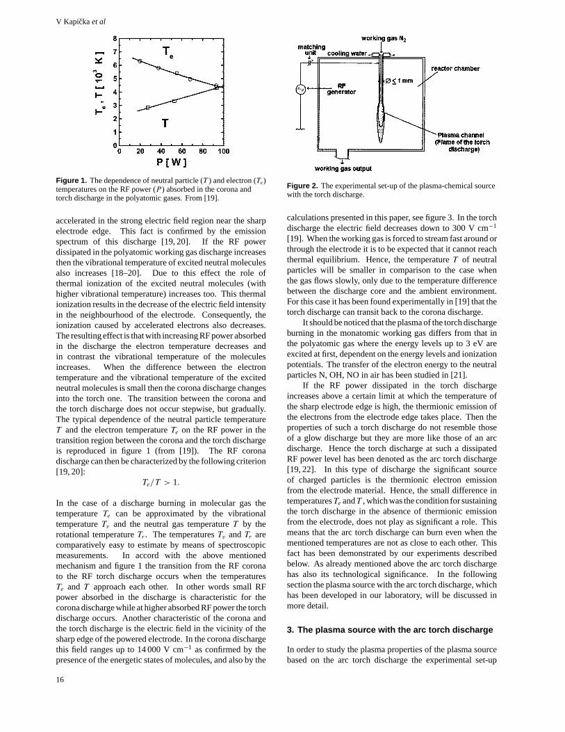
Figure 1. The dependence of neutral particle (T ) and electron (Te)temperatures on the RF power (P ) absorbed in the corona andtorch discharge in the polyatomic gases. From [19].
accelerated in the strong electric field region near the sharpelectrode edge. This fact is confirmed by the emissionspectrum of this discharge [19, 20]. If the RF powerdissipated in the polyatomic working gas discharge increasesthen the vibrational temperature of excited neutral moleculesalso increases [18–20]. Due to this effect the role ofthermal ionization of the excited neutral molecules (withhigher vibrational temperature) increases too. This thermalionization results in the decrease of the electric field intensityin the neighbourhood of the electrode. Consequently, theionization caused by accelerated electrons also decreases.The resulting effect is that with increasing RF power absorbedin the discharge the electron temperature decreases andin contrast the vibrational temperature of the moleculesincreases. When the difference between the electrontemperature and the vibrational temperature of the excitedneutral molecules is small then the corona discharge changesinto the torch one. The transition between the corona andthe torch discharge does not occur stepwise, but gradually.The typical dependence of the neutral particle temperatureT and the electron temperatureTe on the RF power in thetransition region between the corona and the torch dischargeis reproduced in figure 1 (from [19]). The RF coronadischarge can then be characterized by the following criterion[19, 20]:
Te/T > 1.
In the case of a discharge burning in molecular gas thetemperatureTe can be approximated by the vibrationaltemperatureTv and the neutral gas temperatureT by therotational temperatureTr . The temperaturesTv andTr arecomparatively easy to estimate by means of spectroscopicmeasurements. In accord with the above mentionedmechanism and figure 1 the transition from the RF coronato the RF torch discharge occurs when the temperaturesTe and T approach each other. In other words small RFpower absorbed in the discharge is characteristic for thecorona discharge while at higher absorbed RF power the torchdischarge occurs. Another characteristic of the corona andthe torch discharge is the electric field in the vicinity of thesharp edge of the powered electrode. In the corona dischargethis field ranges up to 14 000 V cm−1 as confirmed by thepresence of the energetic states of molecules, and also by the
Figure 2. The experimental set-up of the plasma-chemical sourcewith the torch discharge.
calculations presented in this paper, see figure 3. In the torchdischarge the electric field decreases down to 300 V cm−1
[19]. When the working gas is forced to stream fast around orthrough the electrode it is to be expected that it cannot reachthermal equilibrium. Hence, the temperatureT of neutralparticles will be smaller in comparison to the case whenthe gas flows slowly, only due to the temperature differencebetween the discharge core and the ambient environment.For this case it has been found experimentally in [19] that thetorch discharge can transit back to the corona discharge.
It should be noticed that the plasma of the torch dischargeburning in the monatomic working gas differs from that inthe polyatomic gas where the energy levels up to 3 eV areexcited at first, dependent on the energy levels and ionizationpotentials. The transfer of the electron energy to the neutralparticles N, OH, NO in air has been studied in [21].
If the RF power dissipated in the torch dischargeincreases above a certain limit at which the temperature ofthe sharp electrode edge is high, the thermionic emission ofthe electrons from the electrode edge takes place. Then theproperties of such a torch discharge do not resemble thoseof a glow discharge but they are more like those of an arcdischarge. Hence the torch discharge at such a dissipatedRF power level has been denoted as the arc torch discharge[19, 22]. In this type of discharge the significant sourceof charged particles is the thermionic electron emissionfrom the electrode material. Hence, the small difference intemperaturesTe andT , which was the condition for sustainingthe torch discharge in the absence of thermionic emissionfrom the electrode, does not play as significant a role. Thismeans that the arc torch discharge can burn even when thementioned temperatures are not as close to each other. Thisfact has been demonstrated by our experiments describedbelow. As already mentioned above the arc torch dischargehas also its technological significance. In the followingsection the plasma source with the arc torch discharge, whichhas been developed in our laboratory, will be discussed inmore detail.
3. The plasma source with the arc torch discharge
In order to study the plasma properties of the plasma sourcebased on the arc torch discharge the experimental set-up
16
The high pressure torch discharge plasma source
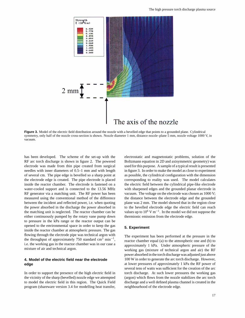
Figure 3. Model of the electric field distribution around the nozzle with a bevelled edge that points to a grounded plane. Cylindricalsymmetry, only half of the nozzle cross-section is shown. Nozzle diameter 1 mm, distance nozzle–plane 5 mm, nozzle voltage 1000 V, invacuum.
has been developed. The scheme of the set-up with theRF arc torch discharge is shown in figure 2. The poweredelectrode was made from thin pipe created from surgicalneedles with inner diameters of 0.5–1 mm and with lengthof several cm. The pipe edge is bevelled so a sharp point atthe electrode edge is created. The pipe electrode is placedinside the reactor chamber. The electrode is fastened on awater-cooled support and is connected to the 13.56 MHzRF generator via a matching unit. The RF power has beenmeasured using the conventional method of the differencebetween the incident and reflected power, i.e. when quotingthe power absorbed in the discharge the power absorbed inthe matching unit is neglected. The reactor chamber can beeither continuously pumped by the rotary vane pump downto pressure in the kPa range or the reactor output can beopened to the environmental space in order to keep the gasinside the reactor chamber at atmospheric pressure. The gasflowing through the electrode pipe was technical argon withthe throughput of approximately 750 standard cm3 min−1,i.e. the working gas in the reactor chamber was in our case amixture of air and technical argon.
4. Model of the electric field near the electrodeedge
In order to support the presence of the high electric field inthe vicinity of the sharp (bevelled) nozzle edge we attemptedto model the electric field in this region. The Quick Fieldprogram (shareware version 3.4 for modelling heat transfer,
electrostatic and magnetostatic problems, solution of theBoltzmann equation in 2D and axisymmetric geometry) wasused for this purpose. A sample of a typical result is presentedin figure 3. In order to make the model as close to experimentas possible, the cylindrical configuration with the dimensioncorresponding to reality was used. The model calculatesthe electric field between the cylindrical pipe-like electrodewith sharpened edges and the grounded planar electrode invacuum. The voltage on the electrode was chosen as 1000 V;the distance between the electrode edge and the groundedplane was 2 mm. The model showed that in the region closeto the bevelled electrode edge the electric field can reachvalues up to 106 V m−1. In the model we did not suppose thethermionic emission from the electrode edge.
5. Experiment
The experiment has been performed at the pressure in thereactor chamber equal (a) to the atmospheric one and (b) toapproximately 1 kPa. Under atmospheric pressure of theworking gas (mixture of technical argon and air) the RFpower absorbed in the torch discharge was adjusted just above100 W in order to generate the arc torch discharge. However,at lower pressures of approximately 1 kPa the RF power ofseveral tens of watts was sufficient for the creation of the arctorch discharge. At such lower pressures the working gas(argon) which flows from the nozzle stabilizes the arc torchdischarge and a well defined plasma channel is created in theneighbourhood of the electrode edge.
17
V Kapickaet al
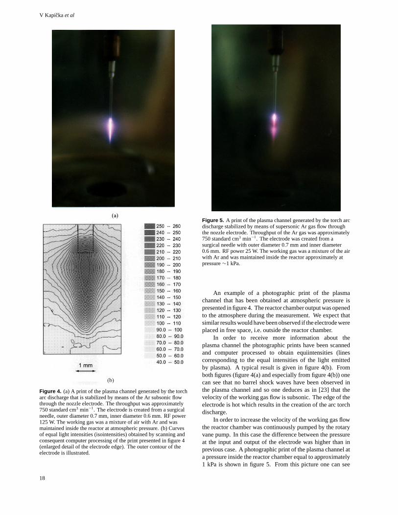
Figure 4. (a) A print of the plasma channel generated by the torcharc discharge that is stabilized by means of the Ar subsonic flowthrough the nozzle electrode. The throughput was approximately750 standard cm3 min−1. The electrode is created from a surgicalneedle, outer diameter 0.7 mm, inner diameter 0.6 mm. RF power125 W. The working gas was a mixture of air with Ar and wasmaintained inside the reactor at atmospheric pressure. (b) Curvesof equal light intensities (isointensities) obtained by scanning andconsequent computer processing of the print presented in figure 4(enlarged detail of the electrode edge). The outer contour of theelectrode is illustrated.
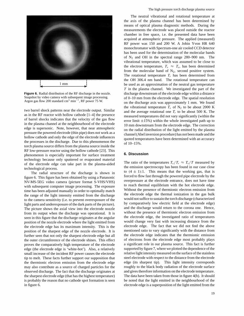
Figure 5. A print of the plasma channel generated by the torch arcdischarge stabilized by means of supersonic Ar gas flow throughthe nozzle electrode. Throughput of the Ar gas was approximately750 standard cm3 min−1. The electrode was created from asurgical needle with outer diameter 0.7 mm and inner diameter0.6 mm. RF power 25 W. The working gas was a mixture of the airwith Ar and was maintained inside the reactor approximately atpressure∼1 kPa.
An example of a photographic print of the plasmachannel that has been obtained at atmospheric pressure ispresented in figure 4. The reactor chamber output was openedto the atmosphere during the measurement. We expect thatsimilar results would have been observed if the electrode wereplaced in free space, i.e. outside the reactor chamber.
In order to receive more information about theplasma channel the photographic prints have been scannedand computer processed to obtain equiintensities (linescorresponding to the equal intensities of the light emittedby plasma). A typical result is given in figure 4(b). Fromboth figures (figure 4(a) and especially from figure 4(b)) onecan see that no barrel shock waves have been observed inthe plasma channel and so one deduces as in [23] that thevelocity of the working gas flow is subsonic. The edge of theelectrode is hot which results in the creation of the arc torchdischarge.
In order to increase the velocity of the working gas flowthe reactor chamber was continuously pumped by the rotaryvane pump. In this case the difference between the pressureat the input and output of the electrode was higher than inprevious case. A photographic print of the plasma channel ata pressure inside the reactor chamber equal to approximately1 kPa is shown in figure 5. From this picture one can see
18
The high pressure torch discharge plasma source
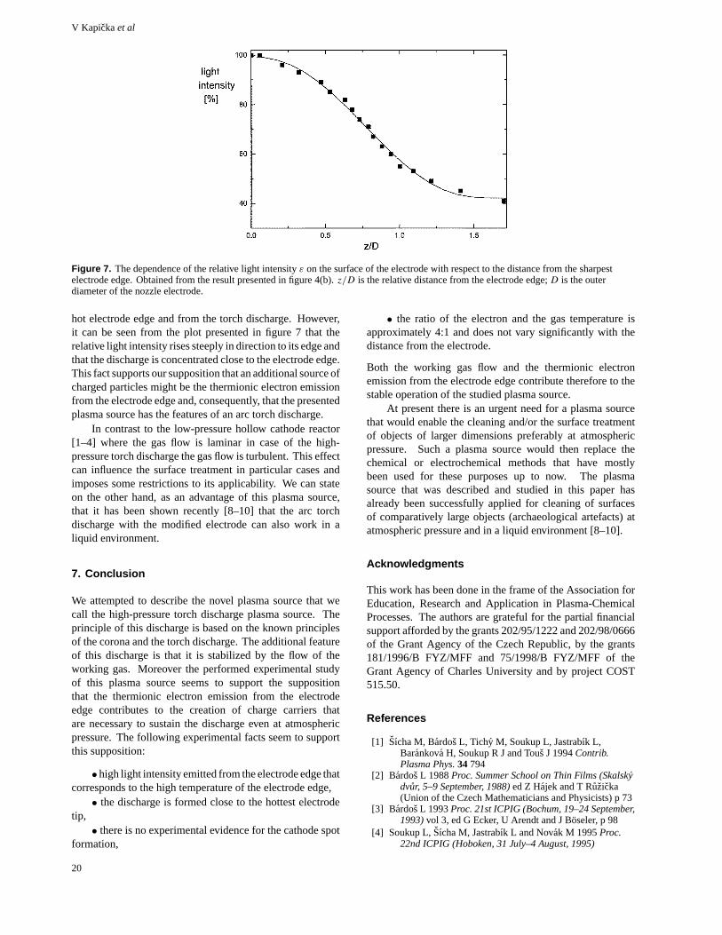
Figure 6. Radial distribution of the RF discharge in the nozzle.Snapshot by video camera with subsequent image processing.Argon gas flow 200 standard cm3 min−1, RF power 75 W.
two barrel shock patterns near the electrode output. Similaras in the RF reactor with hollow cathode [1–4] the presenceof barrel shocks indicates that the velocity of the gas flowin the plasma channel at the neighbourhood of the electrodeedge is supersonic. Note, however, that near atmosphericpressure the powered electrode (thin pipe) does not work as ahollow cathode and only the edge of the electrode influencesthe processes in the discharge. Due to this phenomenon thetorch plasma source differs from the plasma source inside theRF low-pressure reactor using the hollow cathode [23]. Thisphenomenon is especially important for surface treatmenttechnology because only sputtered or evaporated materialof the electrode edge can take part in the plasma-aidedtechnological process.
The radial structure of the discharge is shown infigure 6. This figure has been obtained by using a PanasonicNV-MS-5EG video camera (picture format S-VHS/VHS)with subsequent computer image processing. The exposuretime has been adjusted manually in order to optimally matchthe range of the light intensity emitted from the dischargeto the camera sensitivity (i.e. to prevent overexposure of thelight parts and underexposure of the dark parts of the picture).The picture shows the axial view into the electrode nozzlefrom its output when the discharge was operational. It isseen in this figure that the discharge originates at the angularposition of the nozzle electrode where the light emitted fromthe electrode edge has its maximum intensity. This is theposition of the sharpest edge of the nozzle electrode. It isfurther seen that not only the sharpest electrode edge but allthe outer circumference of the electrode shines. This effectproves the comparatively high temperature of the electrodeedge (the electrode edge is ‘white-hot’). Also, a relativelysmall increase of the incident RF power causes the electrodetip to melt. These facts further support our supposition thatthe thermionic electron emission from the electrode edgemay also contribute as a source of charged particles for theobserved discharge. The fact that the discharge originates atthe sharpest electrode edge (that has the highest temperature)is probably the reason that no cathode spot formation is seenin figure 6.
The neutral vibrational and rotational temperature atthe axis of the plasma channel has been determined bymeans of optical plasma diagnostic methods. During themeasurements the electrode was placed outside the reactorchamber in free space, i.e. the presented data have beenacquired at atmospheric pressure. The applied (measured)RF power was 150 and 200 W. A Jobin Yvon HR 640monochromator with Spectrum-one air cooled CCD detectorhas been used for the determination of the molecular bandsof N2 and OH in the spectral range 280–900 nm. Thevibrational temperature, which was assumed to be close tothe electron temperature,Tv ≈ Te, has been determinedfrom the molecular band of N2, second positive system.The rotational temperatureTr has been determined fromthe OH 306.4 nm band. The rotational temperature canbe used as an approximation of the neutral gas temperatureT in the plasma channel. We investigated the part of thedischarge downstream of the electrode edge within a distanceof 0–10 mm from the electrode edge. The spatial resolutionon the discharge axis was approximately 1 mm. We foundthe vibrational temperatureTv of N2 to be about 2000 Kand the average rotational oneTr to be about 500 K. Themeasured temperatures did not vary significantly (within theerror limit ±15%) within the whole investigated path up to10 mm downstream from the electrode edge. The correctionon the radial distribution of the light emitted by the plasmachannel (Abel inversion procedure) has not been made and thequoted temperatures have been determined with an accuracyof 10–15%.
6. Discussion
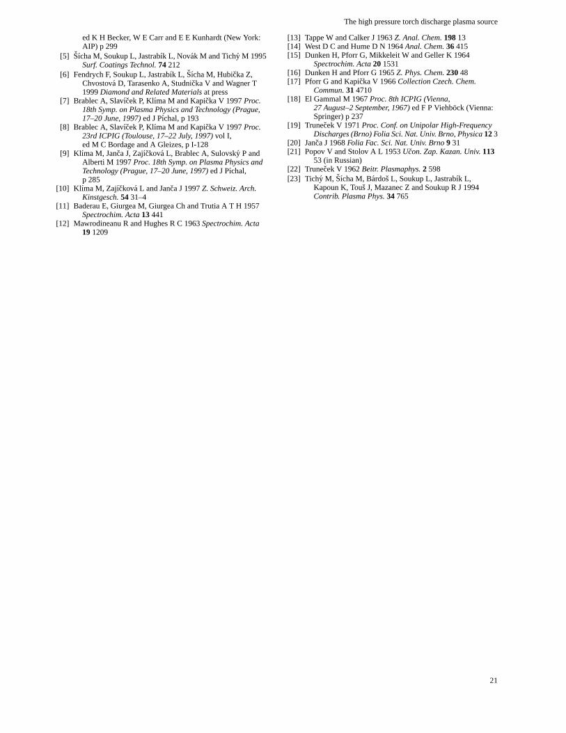
The ratio of the temperaturesTv/Tr ≈ Te/T measured bythe emission spectroscopy has been found in our case closeto (4 ± 1):1. This means that the working gas, that isforced to flow fast through the powered pipe electrode by theoverpressure at the electrode entrance, does not have timeto reach thermal equilibrium with the hot electrode edge.Without the presence of thermionic electron emission fromthe electrode edge the thermal ionization in the gas bulkwould not suffice to sustain the torch discharge (characterizedby comparatively low electric field at the electrode edge)and the discharge would return to the corona one. Hence,without the presence of thermionic electron emission fromthe electrode edge, the investigated ratio of temperatureswould change very fast with increasing distance from theelectrode edge. The fact that we did not find the abovementioned ratio to vary significantly with the distance fromthe electrode edge indicates that the thermionic emissionof electrons from the electrode edge most probably playsa significant role in our plasma source. This fact is furthersupported by figure 7, where we plotted the dependence of therelative light intensity measured on the surface of the stainlesssteel electrode with respect to the distance from the electrodeedge (its sharpest tip). This light intensity correspondsroughly to the black body radiation of the electrode surfaceand gives therefore information on the electrode temperature.The data have been taken from those in figure 4(b). It shouldbe noted that the light emitted in the neighbourhood of theelectrode edge is a superposition of the light emitted from the
19
V Kapickaet al
Figure 7. The dependence of the relative light intensityε on the surface of the electrode with respect to the distance from the sharpestelectrode edge. Obtained from the result presented in figure 4(b).z/D is the relative distance from the electrode edge;D is the outerdiameter of the nozzle electrode.
hot electrode edge and from the torch discharge. However,it can be seen from the plot presented in figure 7 that therelative light intensity rises steeply in direction to its edge andthat the discharge is concentrated close to the electrode edge.This fact supports our supposition that an additional source ofcharged particles might be the thermionic electron emissionfrom the electrode edge and, consequently, that the presentedplasma source has the features of an arc torch discharge.
In contrast to the low-pressure hollow cathode reactor[1–4] where the gas flow is laminar in case of the high-pressure torch discharge the gas flow is turbulent. This effectcan influence the surface treatment in particular cases andimposes some restrictions to its applicability. We can stateon the other hand, as an advantage of this plasma source,that it has been shown recently [8–10] that the arc torchdischarge with the modified electrode can also work in aliquid environment.
7. Conclusion
We attempted to describe the novel plasma source that wecall the high-pressure torch discharge plasma source. Theprinciple of this discharge is based on the known principlesof the corona and the torch discharge. The additional featureof this discharge is that it is stabilized by the flow of theworking gas. Moreover the performed experimental studyof this plasma source seems to support the suppositionthat the thermionic electron emission from the electrodeedge contributes to the creation of charge carriers thatare necessary to sustain the discharge even at atmosphericpressure. The following experimental facts seem to supportthis supposition:
•high light intensity emitted from the electrode edge thatcorresponds to the high temperature of the electrode edge,• the discharge is formed close to the hottest electrode
tip,• there is no experimental evidence for the cathode spot
formation,
• the ratio of the electron and the gas temperature isapproximately 4:1 and does not vary significantly with thedistance from the electrode.
Both the working gas flow and the thermionic electronemission from the electrode edge contribute therefore to thestable operation of the studied plasma source.
At present there is an urgent need for a plasma sourcethat would enable the cleaning and/or the surface treatmentof objects of larger dimensions preferably at atmosphericpressure. Such a plasma source would then replace thechemical or electrochemical methods that have mostlybeen used for these purposes up to now. The plasmasource that was described and studied in this paper hasalready been successfully applied for cleaning of surfacesof comparatively large objects (archaeological artefacts) atatmospheric pressure and in a liquid environment [8–10].
Acknowledgments
This work has been done in the frame of the Association forEducation, Research and Application in Plasma-ChemicalProcesses. The authors are grateful for the partial financialsupport afforded by the grants 202/95/1222 and 202/98/0666of the Grant Agency of the Czech Republic, by the grants181/1996/B FYZ/MFF and 75/1998/B FYZ/MFF of theGrant Agency of Charles University and by project COST515.50.
References
[1] Sıcha M, Bardos L, Tichy M, Soukup L, Jastrabık L,Barankova H, Soukup R J and Tous J 1994Contrib.Plasma Phys.34794
[2] Bardos L 1988Proc. Summer School on Thin Films (Skalskydvur, 5–9 September, 1988)ed Z Hajek and T Ruzicka(Union of the Czech Mathematicians and Physicists) p 73
[3] Bardos L 1993Proc. 21st ICPIG (Bochum, 19–24 September,1993)vol 3, ed G Ecker, U Arendt and J Boseler, p 98
[4] Soukup L,Sıcha M, Jastrabık L and Novak M 1995Proc.22nd ICPIG (Hoboken, 31 July–4 August, 1995)
20
The high pressure torch discharge plasma source
ed K H Becker, W E Carr and E E Kunhardt (New York:AIP) p 299
[5] Sıcha M, Soukup L, Jastrabık L, Novak M and Tichy M 1995Surf. Coatings Technol.74212
[6] Fendrych F, Soukup L, Jastrabık L, Sıcha M, Hubicka Z,Chvostova D, Tarasenko A, Studnicka V and Wagner T1999Diamond and Related Materialsat press
[7] Brablec A, Slavıcek P, Klıma M and Kapicka V 1997Proc.18th Symp. on Plasma Physics and Technology (Prague,17–20 June, 1997)ed J Pıchal, p 193
[8] Brablec A, Slavıcek P, Klıma M and Kapicka V 1997Proc.23rd ICPIG (Toulouse, 17–22 July, 1997)vol I,ed M C Bordage and A Gleizes, p I-128
[9] Kl ıma M, Janca J, Zajıckova L, Brablec A, Sulovsky P andAlberti M 1997Proc. 18th Symp. on Plasma Physics andTechnology (Prague, 17–20 June, 1997)ed J Pıchal,p 285
[10] Kl ıma M, Zajıckova L and Janca J 1997Z. Schweiz. Arch.Kinstgesch.5431–4
[11] Baderau E, Giurgea M, Giurgea Ch and Trutia A T H 1957Spectrochim. Acta13441
[12] Mawrodineanu R and Hughes R C 1963Spectrochim. Acta191209
[13] Tappe W and Calker J 1963Z. Anal. Chem.19813[14] West D C and Hume D N 1964Anal. Chem.36415[15] Dunken H, Pforr G, Mikkeleit W and Geller K 1964
Spectrochim. Acta201531[16] Dunken H and Pforr G 1965Z. Phys. Chem.23048[17] Pforr G and Kapicka V 1966Collection Czech. Chem.
Commun.314710[18] El Gammal M 1967Proc. 8th ICPIG (Vienna,
27 August–2 September, 1967)ed F P Viehbock (Vienna:Springer) p 237
[19] Trunecek V 1971Proc. Conf. on Unipolar High-FrequencyDischarges (Brno) Folia Sci. Nat. Univ. Brno, Physica123
[20] Janca J 1968Folia Fac. Sci. Nat. Univ. Brno9 31[21] Popov V and Stolov A L 1953Ucon. Zap. Kazan. Univ.113
53 (in Russian)[22] Trunecek V 1962Beitr. Plasmaphys.2 598[23] Tichy M, Sıcha M, Bardos L, Soukup L, Jastrabık L,
Kapoun K, Tous J, Mazanec Z and Soukup R J 1994Contrib. Plasma Phys.34765
21
Deposition of polymer films by rf dischargeat atmospheric pressure
P. Slavıcek, V. Bursıkova, A. Brablec, V. Kapicka, M. Klıma
Department of Physical Electronics, Faculty of Science, Masaryk University,
Kotlarska 2, 611 37 Brno, Czech Republic
Received 24 April 2004
In this contribution we report some typical properties of the discharge which hasbeen used for deposition of thin films and some mechanical parameters of thin films. RFplasma nozzle can burn very well even at atmospheric pressure. Special properties of RFdischarges offer hopeful technological applications like deposition of thin solid films. Theknowledge of physical parameters of plasma has been required. The parameters of theplasma were investigated by spectral and optical methods. The powered RF electrode ofthe torch discharge plasma source is made from the metal or dielectric pipe with an innerdiameter of 1÷2 mm and with a length of several centimeters. The electrode is connectedthrough the matching unit to the RF generator driven at the frequency of 13.56 MHz.The mixture of argon and n–hexane or HMDSO (hexamethyldisiloxane, C6H18Si2O) gasflows through the RF electrode at the pipe Fig. 1. Polymer films were deposited on theseveral substrates e.g. glass, brass polished plates and Si wafers.
Special properties of RF discharges offer many hopeful technological applica-tions like deposition of thin solid films, cleaning and treatment of surfaces, restora-tion of archaeological artefact’s, etc. [1 – 4]. It was also demonstrated that this typeof discharges could burn under the liquid level. They can interact with the materialand then new chemical compounds can arise. This special plasma device so called“plasma pencil” was developed in our department. First results of deposition ofthin films at atmospheric pressure by this plasma device were presented last yearon XV Symposium on Physics of Switching Arc [1].
2 Experimental
The powered RF electrode of the torch discharge plasma source is made fromthe metal or dielectric pipe with an inner diameter of 1÷ 2 mm and with a lengthof several centimeters [1 – 4]. The electrode is connected through the matchingunit to the RF generator driven at the frequency of 13.56 MHz. The argon workinggas flows through the RF electrode at the nozzle. The argon with an admixtureof n–hexane or HMDSO goes directly to the discharge. The total gas flow rangedfrom 900 sccm/min to 5000 sccm/min. In case of the deposition from HMDSO/Ar
C586 Czechoslovak Journal of Physics, Vol. 54 (2004), Suppl. C
Deposition of polymer films by rf discharge at atmospheric pressure
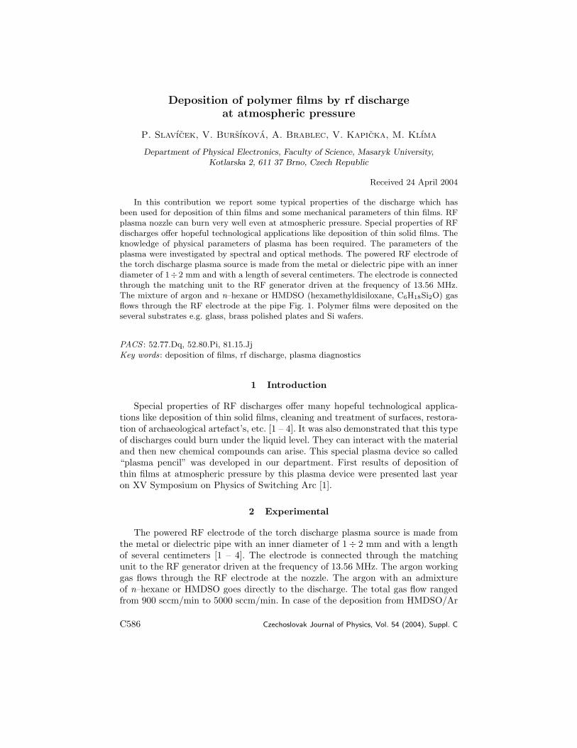
Fig. 1. Experimental set–up: 1 – rf generator, 2 – match unit, 3 – working gas, 4 – dilelec-tric plasma nozzle, 5 – grounded electrode with rotating substrate holder, 6 – substrate
mixture a rotating substrate holder was used in order to enhance the depositionhomogeneity and to suppress the substrate heating.
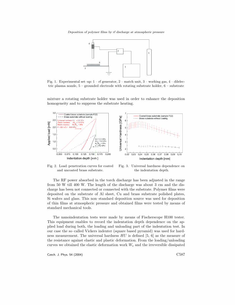
Fig. 2. Load–penetration curves for coatedand uncoated brass substrate.
The RF power absorbed in the torch discharge has been adjusted in the rangefrom 50 W till 400 W. The length of the discharge was about 3 cm and the dis-charge has been not connected or connected with the substrate. Polymer films weredeposited on the substrate of Al sheet, Cu and brass substrate polished plates,Si wafers and glass. This non–standard deposition source was used for depositionof thin films at atmospheric pressure and obtained films were tested by means ofstandard mechanical tools.
The nanoindentation tests were made by means of Fischerscope H100 tester.This equipment enables to record the indentation depth dependence on the ap-plied load during both, the loading and unloading part of the indentation test. Inour case the so–called Vickers indenter (square based pyramid) was used for hard-ness measurement. The universal hardness HU is defined [5, 6] as the measure ofthe resistance against elastic and plastic deformation. From the loading/unloadingcurves we obtained the elastic deformation work We and the irreversible dissipated
Czech. J. Phys. 54 (2004) C587
P. Slavıcek et al.
indentation work Wirr:
HU =L
26.43h2, (1)
Wtotal =∫ hmax
h=0
L1(h)dh , We =∫ hmax
hmin
L2(h)dh , Wirr = Wtotal −Wel , (2)
where h is the penetration depth at applied load L, L1(h) is the loading curve andL2(h) is the unloading curve.
From the load–penetration curves it was possible to determine also the mate-rial resistance against plastic deformation Hpl (so called plastic hardness) and theelastic modulus Y .
Hpl =Lmax
26.43h2r
, (3)
hr is the depth of the remained indentation print created by irreversible deforma-tion under maximum load Lmax. The indentation elastic modulus Y of the testedmaterial can be calculated on the basis of the contact model in the following way:
1Y
=1Er− (1− ν2
i )Ei
, Er =√πdL(hmax)/dh
2√A(h)
. (4)
Here Er is the so called reduced elastic modulus, dL(hmax)/dh is the slope of theunloading curve at maximum load (depth) and A(h) is the projected contact area,when the maximum indentation depth is h. Ei and νi are the elastic modulus andthe Poisson ratio of the indenter material.
3 Results
Each measurement was repeated at least nine times in order to check the re-producibility of the nanoindentation measurement. The indentation tests were pro-vided at several different load and we studied also the fracture toughness of thecoating/substrate systems. The coatings prepared on silicon substrate showed verylow resistance against the indentation test.
Thin films on sample P22 and P29 were made by plasma device with metalnozzle and the discharge has been not connected with the substrate. The resistanceof the coatings on brass substrates was much higher. Fig. 2, 3 shows the results of thenanoindentation tests on sample P22. In that case the test were provided on bothcoated and uncoated part of the brass substrate for the same maximum penetrationdepth hmax = 160 nm, in order to get comparable load penetration curves. Asit is shown in Fig. 2, 3, the coated part exhibited much higher resistance againstpenetration test as the uncoated part. The universal hardness HU increased from 2.2to 3.8 GPa and the calculated plastic hardness increased from 3.2 to 7.6 GPa. Therewas also an increase in the elastic modulus Y from 75 to 90 GPa. The elastic to
C588 Czech. J. Phys. 54 (2004)
Deposition of polymer films by rf discharge at atmospheric pressure
total deformation work ratio We/Wtot increased from 25 to 39 %. These parameterscharacterize the whole system of the coating and the substrate. The films are verythin and there is still an influence of the substrate on the measured characteristicsas it is shown in Fig. 2, 3 on the universal hardness dependence on the indentationdepth.
0,0 0,1 0,2 0,3 0,4
0
2
4
6
8
10
12
influence of the coating
Coated brass substrate (sample P22) Brass substrate without coating
App
lied
Load
[mN
]
Indentation Depth [�m]
0,0 0,1 0,2 0,3 0,40
2
4
6
8
10
12
cracking of the coating
coating's influence
Coated brass substrate (sample P29) Brass substrate without coating
App
lied
Load
[mN
]
Indentation Depth [�m]
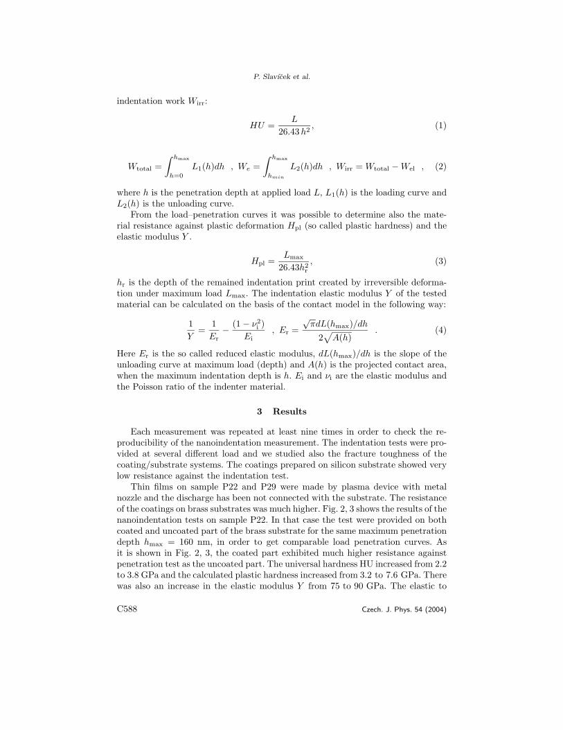
Fig. 4. Load–penetration curves obtainedon sample P22 for maximum load of 10 mN.Deposition time 10 min, rf power 125 W.
Fig. 5. Load–penetration curves obtainedon sample P29 for maximum load of10 mN (right). Deposition time 5 min,
rf power 125 W.
The film resistance appeared on the measured universal hardness up to 60 nm(5 GPa) of the penetration depth, after that the influence of the substrate begunto be substantial. The nanoindentation tests were compared with microindentationtests. In Fig. 4 are shown the load–penetration curves obtained for maximum loadof 10 mN for coated and uncoated part of the substrate (P22). The influence of thefilm resistance appeared on the part of the loading curve. The fracture toughnessof the substrate was high, there were no cracks in the film or at the film/substrateinterface. In Fig. 5, in the case of the sample P29, the influence of the film was sub-stantial up to higher depths (250 nm), but after that coating fracture was observed.The cracking appeared on the loading curve as a significant jump. The hardness ofthe film P29 was about 8 GPa.
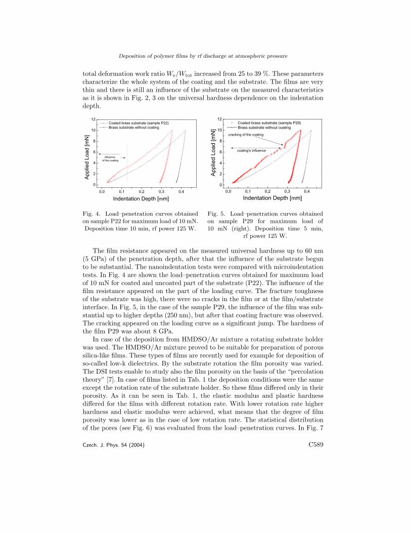
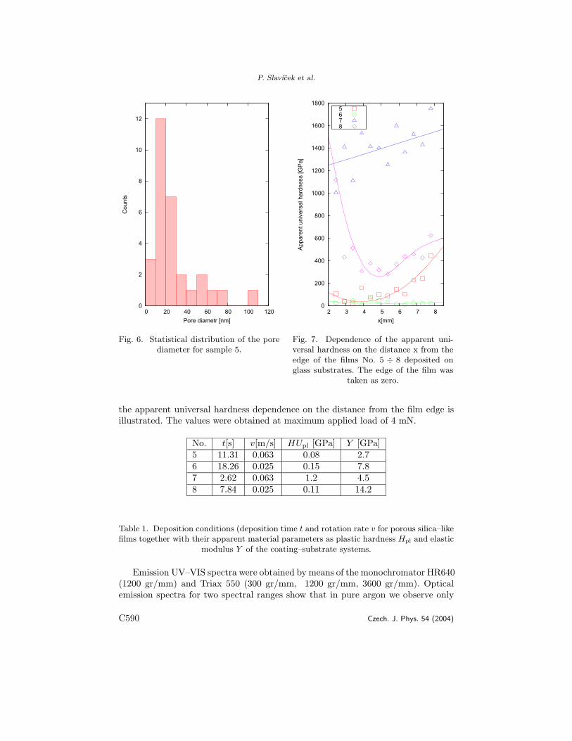
In case of the deposition from HMDSO/Ar mixture a rotating substrate holderwas used. The HMDSO/Ar mixture proved to be suitable for preparation of poroussilica-like films. These types of films are recently used for example for deposition ofso-called low-k dielectrics. By the substrate rotation the film porosity was varied.The DSI tests enable to study also the film porosity on the basis of the “percolationtheory” [7]. In case of films listed in Tab. 1 the deposition conditions were the sameexcept the rotation rate of the substrate holder. So these films differed only in theirporosity. As it can be seen in Tab. 1, the elastic modulus and plastic hardnessdiffered for the films with different rotation rate. With lower rotation rate higherhardness and elastic modulus were achieved, what means that the degree of filmporosity was lower as in the case of low rotation rate. The statistical distributionof the pores (see Fig. 6) was evaluated from the load–penetration curves. In Fig. 7
Czech. J. Phys. 54 (2004) C589
P. Slavıcek et al.
0
2
4
6
8
10
12
0 20 40 60 80 100 120
Cou
nts
Pore diametr [nm]
0
200
400
600
800
1000
1200
1400
1600
1800
2 3 4 5 6 7 8
App
aren
t uni
vers
al h
ardn
ess
[GP
a]
x[mm]
5 6 7 8
Fig. 6. Statistical distribution of the porediameter for sample 5.
Fig. 7. Dependence of the apparent uni-versal hardness on the distance x from theedge of the films No. 5 ÷ 8 deposited onglass substrates. The edge of the film was
taken as zero.
the apparent universal hardness dependence on the distance from the film edge isillustrated. The values were obtained at maximum applied load of 4 mN.
Table 1. Deposition conditions (deposition time t and rotation rate v for porous silica–likefilms together with their apparent material parameters as plastic hardness Hpl and elastic
modulus Y of the coating–substrate systems.
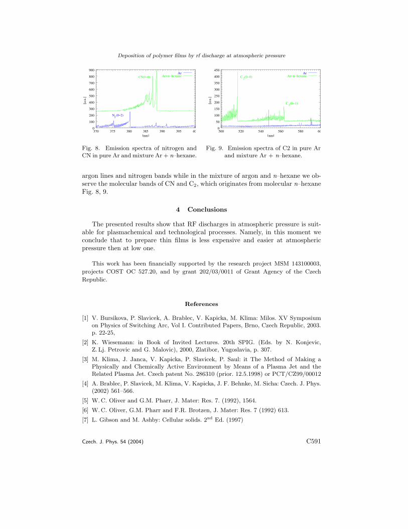
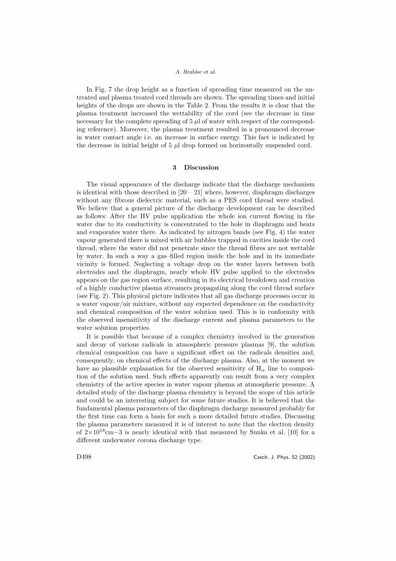
Emission UV–VIS spectra were obtained by means of the monochromator HR640(1200 gr/mm) and Triax 550 (300 gr/mm, 1200 gr/mm, 3600 gr/mm). Opticalemission spectra for two spectral ranges show that in pure argon we observe only
C590 Czech. J. Phys. 54 (2004)
Deposition of polymer films by rf discharge at atmospheric pressure
CN(0−0)
N (0−2)2
0
100
200
300
400
500
600
700
800
900
370 375 380 385 390 395 40
[a.u
.]
[nm]
ArAr+n−hexane C (0−0)
C (0−1)
2
2
0
50
100
150
200
250
300
350
400
450
500 520 540 560 580 60
[a.u
.]
[nm]
ArAr+n−hexane
Fig. 8. Emission spectra of nitrogen andCN in pure Ar and mixture Ar + n–hexane.
Fig. 9. Emission spectra of C2 in pure Arand mixture Ar + n–hexane.
argon lines and nitrogen bands while in the mixture of argon and n–hexane we ob-serve the molecular bands of CN and C2, which originates from molecular n–hexaneFig. 8, 9.
4 Conclusions
The presented results show that RF discharges in atmospheric pressure is suit-able for plasmachemical and technological processes. Namely, in this moment weconclude that to prepare thin films is less expensive and easier at atmosphericpressure then at low one.
This work has been financially supported by the research project MSM 143100003,
projects COST OC 527.20, and by grant 202/03/0011 of Grant Agency of the Czech
Republic.
References
[1] V. Bursikova, P. Slavicek, A. Brablec, V. Kapicka, M. Klima: Milos. XV Symposiumon Physics of Switching Arc, Vol I. Contributed Papers, Brno, Czech Republic, 2003.p. 22-25,
[2] K. Wiesemann: in Book of Invited Lectures. 20th SPIG. (Eds. by N. Konjevic,Z. Lj. Petrovic and G. Malovic), 2000, Zlatibor, Yugoslavia, p. 307.
[3] M. Klima, J. Janca, V. Kapicka, P. Slavicek, P. Saul: it The Method of Making aPhysically and Chemically Active Environment by Means of a Plasma Jet and theRelated Plasma Jet. Czech patent No. 286310 (prior. 12.5.1998) or PCT/CZ99/00012
[4] A. Brablec, P. Slavicek, M. Klima, V. Kapicka, J. F. Behnke, M. Sicha: Czech. J. Phys.(2002) 561–566.
[5] W. C. Oliver and G.M. Pharr, J. Mater: Res. 7. (1992), 1564.
[6] W. C. Oliver, G.M. Pharr and F.R. Brotzen, J. Mater: Res. 7 (1992) 613.
[7] L. Gibson and M. Ashby: Cellular solids. 2nd Ed. (1997)
Czech. J. Phys. 54 (2004) C591
Chem. Listy 102, s1338−s1340 (2008) II Central European Symposium on Plasma Chemistry 2008
s1338
RF DISCHARGE AT ATMOSPHERIC PRESSURE – DIAGNOSTICS AND APPLICATIONS PAVEL SLAVICEK*a, MILOS KLIMAa, DANA SKACELOVAa, EVA KEDRONOVAa, ANTONIN BRABLECa, and VLADIMIR AUBRECHTb
a Department of Physical Electronics, Faculty of Science, Masaryk University, Kotlarska 2, 611 37 Brno, b Department of power electrical and electronic engineering,Brno Univer-sity of Technology, Technicka 8, budova A3, 61600, Brno, Czech Republic [email protected] 1. Introduction
Low temperature plasmas are extensively used for the plasma processing1, light sources, various plasma technologi-es2 etc. During several last years different plasma discharges with nozzle and powered by rf generator driven at frequency 13,56 MHz have been investigated. Plasma pencil is a special type of plasma nozzle working at atmospheric pressure, which is interesting for possible applications6,8 such as local treat-ment of surface, deposition of thin films, change surface en-ergy, cutting in surgery, etc. Through this nozzle, which is made from quartz tube with typical inner diameter 2 mm, flows working gas (argon with water vapour). The powered electrode is connected through the maching unit to the rf gen-erator.
In the contribution, we present diagnostics of unipolar discharge channel generated by the plasma pencil at atmos-pheric pressure. For different electrical parameters and vari-ous construction design of the plasma pencil the parameters of the plasma channel are estimated from optical emission spec-tra in the spactral range 200–900 nm: rotation temperature from OH rotational lines, vibrational temperature from nitro-gen bands as well as concentration of electons and tempera-ture of neutral gas from Stark and Doppler broadening of hydrogen lines, resp.
2. Experimental setup
The plasma pencil is shown in Fig. 1. The powered elec-
trode of was separated by the dielectric quartz tube, nozzle
with the inner diameter 2 mm and the outer diameter 4 mm and 50 mm length. As an active medium flowing through the hollow electrode of the plasma pencil argon with purity 99.996 % was used. Note, that the working gas flowing from the nozzle stabilises the dischrge. The hollow electrode was connected through the matching network to the rf generator Cesar – 1310 by Dresler driven at frequency 13,56 MHz5−7.
Optical emission spectroscopy was accomplished by means of the monochromator FHR 1000 by Jobin-Yvon-Horiba supplied with CCD detector and ICCD (Intensified Charge Couple Device) system. CCD detector in “continual” regime was used, ICCD system in pulse regime was chosen whereas square pulse modulation frequency of 27 kHz by means of external triggering generator Agilent 33220A was adjusted.
The spectra was recorded perpendicularly to the plasma channel for different discharge parameters.
The rotational temperature from rotational lines of OH, the electron temperature from Ar lines in the plasma channel at different conditions of discharge (power supply, frequency, length) were determined. Rotational and electron temperature were calculated from Boltzmann plot3,4.
The most frequently used technique for determination of electron concentration Ne is based on the half-width and shape of the hydrogen Balmer beta (Hβ = 486.13 nm) spectral line.
Electron concentration was estimated by approximate formula e.g.() by Weise et al9,10,12 .
Ws is the Stark halfwidth at half maximum (HWHM) of
line. In case when Stark width, Ws, is small and comparable
N e[m−3]= 1022��W s
4 . 7333�1.49
Fig. 1. Photograph of plasma pencil
Fig. 3. Drop of water on thin hydrophobic layer surface. This layer was deposited by plasma pencil at atmospheric pressure
Fig. 2. Thin hydrophobic layer on glass
Chem. Listy 102, s1338−s1340 (2008) II Central European Symposium on Plasma Chemistry 2008
s1339
with Doppler and/or instrumental broadening it may be deter-mined by using an approximate deconvolution formula11.
In calculation of electron concentration other broadening mechanism such as resonance and Van der Waals broadening were ignored, because Stark broadening was dominant. 3. Results and discussion
A typical distribution of rotational temperature esti-mated from OH lines as a function of the distance from the end of the nozzle for fixed gas flow of 1 l min−1 and fixed hf power input of 125 W is shown in Fig. 4. The negative dis-tance was taken in the nozzle while the positive values were taken out of the nozzle and the lenth of nozzle was 50 mm.
The rotational temperature is aproximately constant along the nozzle. In side the nozzle rotational temperature insreases fast.
Fig. 5 shown a distribution of concentration of electrons as function of the distance from the end of the nozzle for fixed gas flow of 1 l min−1 and fixed hf power input of 125 W. The negative distance was taken in the nozzle while the positive values were taken out of the nozzle. Concentration of elec-trons, calculated from the half-width and shape of the hydro-gen Balmer beta line Hβ = 486,13 nm, decreases along the nozzle from electrode to the end of the nozzle.
A typical distribution of electron temperature and rota-tional temperature as a function of the delay while using ICCD system in pulse regime, square pulse modulation fre-quency of 27 kHz and duty cycle 50 % is shown in Fig. 6. and Fig. 8. Gas flow of 1 l min−1 and hf power input of 135 W in the end of the nozzle. Is evidently, that the temperature is measurable only in the range of modulation pulse. Fig. 4. Rotational temperature estimated from OH lines as
a function of the distance from the end of the nozzle for fixed gas flow of 1 l min−1 and fixed hf power input of 125 W. The negative distance was taken in the nozzle while the positive values were taken out of the nozzle.
Fig. 5. Concentration of electrons as function of the distance from the end of the nozzle for fixed gas flow of 1 l min−1 and fixed hf power input of 125 W. The negative distance was taken in the nozzle while the positive values were taken out of the nozzle
Fig. 6. Electron temperature calculated from Ar lines as a func-tion of the delay while using ICCD detector for fixed gas flow of 1 l min−1 and fixed hf power input of 135 W in the end of the nozzle. Pulse modulation frequency of 27 kHz was adjusted
Fig. 7. Intensity of OH lines as a function of the delay while using ICCD detector for fixed gas flow of 1 l min−1 and fixed hf power input of 135W in the end of the nozzle. Pulse modulation frequency of 27 kHz was adjusted
Chem. Listy 102, s1338−s1340 (2008) II Central European Symposium on Plasma Chemistry 2008
s1340
Fig. 7 shows a distribution of intinsity of one rotational line of OH molecul as a function of delay in pulse regime of discharge.
Pulse regime of discharges are perspective for deposi-tion of thin layer on thermal sensitive materials and for other applications..
This discharge in „continual“ regime was used for depo-sition thin layers on glass substrates. For this deposition mix-ture of Ar and hexamethyldisiloxane (HMDSO) was used as working gas.
High speed camera Olympus i-SPEED-2 was used for demonstration of properties of this thin films. Record speed 1000 frames per second was used. Fig. 2 and Fig. 3 show pictures accompilshed by this camera. Pictures show drops of water on hydrophobic thin films deposited on glass substrates. This are first hydrophobic films deposited by this plasma device at atmospheric pressure.
4. Conclusion
In this article results of electron concentration, rotational and electron temperature in discharge generated by plasma pencil at atmospheric pressure were presented for „continual“ and pulse regime.
First results of deposition of hydrophobic thin films on glass substrates by plasma pencil were presented too.
In this contribution the single nozzle was used, but sev-eral nozzles can be applied simultaneously in one device, which is more convenient for practical application. This research has been supported by the grant 202/07/1207, by the Czech Science Foundation and by the research intent MSM:0021622411 funding by the Ministry of Education of the Czech republic and Grant Agency of Academy of Science of Czech Republic contract No. KAN101630651. REFERENCES 1. Rahel J., Simor M., Cernak M., Stefecka M., Imahori Y.,
Kando M.: Surf. Coat. Technol. 169-170, 604 (2003). 2. Sira M., Trunec D., Stahel P., Bursikova V., Navratil J.:
Phys. D 41, 015205 (2008). 3. Griem H. R.: Principles of Plasma Spectroscopy. Aca-
demic Cambridge Univ. Press, New York 1997. 4. Lochte-Holtgreven Ed W.: Plasma Diagnostics. Ameri-
can Institute of Physics, New York 1995. 5. Cada M., Hubicka Z., Sicha M., Churpita A., Jastrabik
9. Zikic R., Gigisos M. A., Ivkovic M., Gonzales M. A., Konjevic N.: Spectrochim. Acta, Part B 57, 987 (2002).
10. Kelleher D. E. : J. Quant. Spectrosc. Radiat. Transfer 25, 191 (1981).
11. Ivkovic M., Jovicevic S., Konjevic N.: Spectrochim. Acta, Part B 59, 591 (2004).
12. Zikic R., Gigisos M. A., Ivkovic M., Gonzales M. A., Konjevic N.: Spectrochim. Acta, Part B 57, 987 (2002).
Fig. 8. Rotational temperature calculated from OH lines as a function of the delay while using ICCD detector for fixed gas flow of 1 l min−1 and fixed hf power input of 135 W in the end of the nozzle. Pulse modulation frequency of 27 kHz was adjusted
Gas plasmas and plasma modified materials in medicine
Sadiqali Cheruthazhekatt1, Mirko Černák2, Pavel Slavíček2, Josef Havel1, 2
1Department of Chemistry, Faculty of Science, Brno, Czech Republic2Department of Physical Electronics, Faculty of Science, Brno, Czech Republic
Received 8th February 2010.Revised 25th March 2010.Published online 19th April 2010.
SummaryThe applications of gas plasma and plasma modified materials in the emerging fields of medicine such asdentistry, drug delivery, and tissue engineering are reviewed. Plasma sterilization of both living and non-living objects is safe, fast and efficient; for example plasma sterilization of medical equipment quicklyremoves microorganisms with no damage to the tiny delicate parts of the equipment and in dentistry it offersa non-toxic, painless bacterial inactivation of tissues from a dental cavity. Devices that generate plasma insidethe root canal of a tooth give better killing efficiency against bacteria without causing any harm to thesurrounding tissues. Plasma modified materials fulfill the requirements for bioactivity in medicine; forexample, the inclusion of antimicrobial agents (metal nano particles, antimicrobial peptides, enzymes, etc.)in plasma modified materials (polymeric, metallic, etc) alters them to produce superior antibacterialbiomedical devices with a longer active life. Thin polymer films or coating on surfaces with different plasmaprocesses improves the adherence, controlled loading and release of drug molecules. Surface functionalizationby plasma treatment stimulates cell adhesion, cell growth and the spread of tissue development. Plasmaapplications are already contributing significantly to the changing face of medicine and future trends arediscussed in this paper.
PEG, poly(ethylene glycol)PHBV, poly(3-hydroxybutyric acid- co-3-hydroxyvaleric acid)PIII, plasma immersion and ion implantationPP, polypropylenePSDVB, polystyrene-divinylbenzenePU, polyurethanesRF, radio frequencyS. aureus, Staphylococcus aureusS. mutans, Streptococcus mutans
INTRODUCTION
Plasma is considered as the fourth state of matter andit is the most abundant state in the universe. It existsin a variety of forms among which is ‘fire’, known formillions of years, since the early stone age. Plasma isnot a human invention, and is present in nature, as fire
Josef Havel, Department of Chemistry,Faculty of Science, Masaryk University,Kotlářská 2, 611 37 Brno, Czech Republic
Cheruthazhekatt et al.: Gas plasmas and plasma modified materials in medicine
56
in the sun, stars, in the tails of comets and as flashesof lightning (Conrads and Schmidt 2000). In medicineand biology ‘plasma’ refers to the non-cellular fluidcomponent of blood. The term was introduced intophysics by Irving Langmuir in 1928, because itresembles the ionic liquids in biology and medicine.
The number of applications of plasma technologyin many fields including microelectronics, metallurgy,polymer engineering, and biomedical engineering, isgrowing rapidly. One of the advantages of thistechnology is that surface properties such as hardness,corrosion resistance and other chemical and physicalproperties can be selectively modified withoutaffecting the bulk characteristics of the materials. Theuse of synthetic materials in biomedical applicationshas increased dramatically during the past fewdecades. However some synthetic biomaterials, forexample polymeric implants, can, in biosystems,cause problems, such as microbial growth and/oradsorption of bioorganisms. The simple addition ordeposition of bioactive molecules to such materialscan offer less stability and uniformity than covalentlybonded species. In comparison with other methods forsurface modification (layer by layer deposition,dipping, etc.) plasma surface modification offers ashorter and more economical method for the covalentattachment of bioactive molecules to the substratewithout obstructing the bulk properties (Chu et al.2002, Oehr 2003). Thus plasma technology has greatimportance in the development of new biomaterials.In medicine direct plasma treatment for sterilization,deactivating pathogens, blood clotting, woundhealing, cancer treatment, etc. is more effective thanany other method. Thus, plasma and plasma modifiedmaterials play an important role in our daily live,making it more convenient and healthier.
Several reviews of the biomedical application ofplasma and plasma treated materials have beenpublished (Fridman et al. 2008, Gomathi et al. 2008,Laroussi 2008, Desmet et al. 2009), but to date, nonegives an overview of modern applications of plasmaand plasma modified materials in medicine; the aimof this review is therefore to present a survey ofrecent advances of plasma and plasma modifiedmaterials in this field.
PLASMA FORM OF MATTER ANDMETHODS FOR GENERATION
On the application of sufficient heat, a solid materialtransforms firstly into a liquid and then. at a highertemperature, into a gas. As the energy supplied isincreased, the electrons receive sufficient energy to
separate from the atoms or molecules of gas andbecome electrically conductive. In this way gasundergoes a phase transition to a partially orcompletely ionized gas, called the plasma state. Fig. 1illustrates the phase transformations of matter bychanges in the energy of the system under processessuch as melting, vaporization, ionization, etc.
Fig. 1. Different states of matter.
Plasma consists of a mixture of positively andnegatively charged ions, electrons and neutral species(atoms, molecules). It can be divided into two maincategories; hot plasma (near-equilibrium plasma) andcold plasma (non-equilibrium plasma). Hot plasmaconsists of very high temperature particles and theyare close to the maximal degree of ionization. Coldplasma is composed of low temperature particles andrelatively high temperature electrons and they have alow degree of ionization (Tendero et al. 2006). Coldplasma can be further subdivided into low pressureand atmospheric pressure cold plasma. Atmosphericpressure cold plasma is the basis of one of the mostpromising methods of achieving a more flexible,reliable, less expensive and continuous method ofsurface modification (Bogaerts et al. 2002). Differentforms of energy (thermal, electric current,electromagnetic radiations, light from a laser, etc.) areused to create the plasma regardless of the nature ofthe energy source. Depending on the type of energysupplied and the amount of energy transferred to theplasma, the properties of the plasma change in termsof electron density or temperature (Braithwaite 2000).In common, man made, plasma, electrical energy isusually injected into a system in a continuous mannerin order to avoid stoppage of the plasma discharge.Plasma is most commonly produced by passing anelectric current through the gas. Different frequenciesof power sources – direct current, alternating current,low frequency, radio frequency, microwave, etc. areused for the generation of discharges such asatmospheric and low pressure glow discharge, corona,magnetron and dielectric barrier discharge (DBD)(Conrads and Schmidt 2000, Denes and Manolache
Cheruthazhekatt et al.: Gas plasmas and plasma modified materials in medicine
57
2004). An example of a high frequency plasma jetpencil is given in Fig. 2 (Klíma et al. 1998, 2003,2005) and plasma generated by a surface coplanarbarrier discharge in ambient air atmosphere is givenin Fig. 3. Plasma parameters must be designedspecifically for a given application asplasma sourceshave their own peculiarities, advantages, anddisadvantages. The selection of a plasma source anddesign for the production of novel material is a greatchallenge for scientists and industry.
Fig. 2. (A) Plasma pencil device. (B) Magnified plasmapencil torch glowing in a quartz tube and in air. (C) Multijet system. (D) Magnified multi jests modifying the surface.Photo: M. Klíma (reproduced with permission).
Fig. 3. Scheme of barrier discharge generation. (A)Plasma of surface barrier discharge and (B) Illustration ofsafety of the surface coplanar barrier discharge burning inambient air atmosphere.
PLASMA TREATMENT IN MEDICINE
Heat and high temperature (steam, hot metal objects)have been used in medicine for a significant length oftime: in tissue removal, blood clotting, wound healingand for the disinfection of both living and non-livingbiomedical articles. Direct contact with hot metal willaffect the surrounding tissues in living organisms bytissue adhesion, restarting of bleeding, charring of the
neighbouring tissues and causes damage to heatsensitive biomedical articles. Treatment with lowtemperature plasma provides an alternative method ofavoiding the difficulties associated with this ancientmethod (Hayashi et al. 2006, Fridman et al. 2008),because the ions and the neutral species in lowtemperature plasma are relatively cold and do notcause any thermal damage to articles which come incontact with the plasma. This non-thermal behaviorrecommends the use of gas plasma for the treatmentof heat sensitive materials including biological matter,such as cells and tissues (Laroussi 2005). In recentyears, non-thermal atmospheric plasma effects havebeen developed to extend the plasma treatment ofliving tissue. These can be selective in achieving adesired result for some living matter, while havinglittle or no effect on the surrounding tissue (Fridmanet al. 2008), and have found application in low heatsurface modification of polymers (Gomathi et al.2008), clinical instrument sterilization, tissueengineering and dental cavity treatment (Shenton andStevens 2001, Denes and Manolache 2004, Laroussi2005). Many different types of plasma devicesincluding plasma pencils, radio frequency plasmaneedles, direct current plasma brushes and plasma jetshave been developed for non-thermal atmosphericpressure plasma generation (Laroussi et al. 2008, Nieet al. 2009). A brief overview of gas plasmaapplications in medicine is given in Fig. 4.
Fig. 4. Gas plasma uses in medicine.
Plasma sterilizationPlasma sterilization is a well established technologyin medicine. Plasma, in the form of fire, was used forsterilization thousands of years ago. The sterilization
Gas Plasma in Medicine
Plasma Modified Materials
Plasma JetsPencilsNeedlesBrushes
Sterilization
Blood ClottingTreatment of
Diseases
Dentistry
Surgery
Tissue Engineering
ImplantsAntimicrobial
Materials
Drug Delivery
Ophthalmology
Plasma Devices
Polymers Metals
Ceramics
Gas Plasma in Medicine
Plasma Modified Materials
Plasma JetsPencilsNeedlesBrushes
Sterilization
Blood ClottingTreatment of
Diseases
Dentistry
Surgery
Tissue Engineering
ImplantsAntimicrobial
Materials
Drug Delivery
Ophthalmology
Plasma Devices
Polymers Metals
Ceramics
Cheruthazhekatt et al.: Gas plasmas and plasma modified materials in medicine
58
of living objects, such as human, animal, and planttissues is of much interest in medicine (Crow andSmith 1995). Plasma sterilization works at theatomic/molecular level and therefore it helps to reachall surfaces, including the interior parts of medicalequipment (catheters, needles, syringes, etc.) andother regions which are not accessible to fluiddisinfectants (Fridman et al. 2007). It has severaladvantages (see Fig. 5) over commonly usedsterilization methods such as heat, chemical solutions,or gas and radiation bombardment which causethermal, chemical, or irradiation damage to bothliving and non-living objects. The parametric study ofplasma for sterilization is of importance inunderstanding and controlling the deactivation ofmicrobes, because the main sterilizing factors arestrongly dependent on the plasma source type and/orthe plasma characteristics. Nowadays non-thermalatmospheric pressure plasma is more frequently usedfor the sterilization of both living and non-livingmaterials (Lerouge et al. 2001, Trompeter et al. 2002,Xingmin et al. 2006, Fridman et al. 2008, Moreau etal. 2008).
Fig. 5. Some advantages of plasma sterilization.
Sterilization of living materialsSeveral types of plasma device have been reported forthe sterilization of living animal and human tissues.An electrically safe DBD plasma with a floatingelectrode set up has been reported for the sterilizationof living tissue. This method provides complete tissuesterilization within seconds, with no damage to skinsamples (Fridman et al. 2006). Recently a new DBDnon-thermal plasma at atmospheric pressure withconical geometry structured electrodes was developedfor evaluating the bactericidal effect againstPseudomonas aeruginosa (P. aeruginosa), Bacilluscereus (B. cereus) and Escherichia coli (E. coli)bacteria. The complete removal of these
microorganisms was effected within an exposure timeof 10 min for P. aeruginosa, and 15 min for E. coliand B. cereus, respectively (Sohbatzadeh et al. 2009).Low power radio frequency (RF) plasma atatmospheric pressure with a helium flow is used forthe no damaging sterilization of living tissues. Thisplasma has the capacity to kill different kinds ofbacteria: E. coli, P. aeruginosa and Staphylococcusaureus (S. aureus) with a decimal reduction time of1–2 minutes, while preserving the living cells of thesubstrate (Martines et al. 2009). Gweon et al. (2009)studied the sterilization mechanisms and the majorsterilization factors of RF plasma, with E. coli as thetarget. They found that sterilization is more effective(up to 40%) with 0.15% oxygen added to the heliumgas supply. Moon et al. (2009), generated a relativelylarge area (110 mm × 25 mm) of RF discharges withlow current and low gas temperature at atmosphericpressure to carry out treatment on living tissue. Theyinvestigated possible electrical and thermal damageand also the sterilization efficiency for living celltreatment which was tested with microorganismsinoculated on pork and human skin surfaces.
Sterilization of non-living materialsThe sterilization of medical equipment is an importantprocedure for disinfection in hospitals, and a numberof medical plasma sterilizer devices have beenintroduced (Griffiths 1993, Herrmann et al. 1999, Linet al. 1999, Montie et al. 2000, Gaunt et al. 2006,Laroussi et al. 2006).
The removal of protein residues from surgicalinstruments is quite difficult and commonly usedsterilization and decontamination techniques cancause major damage to the objects treated. Kylián etal. (2008) developed a low pressure inductivelycoupled (Ar/O2 mixture) plasma discharge for theremoval of model proteins from different substratematerials ranging from metallic surfaces to polymericmaterials. Ar/O2 mixture represents a favorable optioncompared to the discharges sustained in other gases orgas mixtures, since it allows for the fast eliminationof proteins and killing of bacterial spores. Moreover,the application of this mixture overcomes theenvironmental and safety drawbacks of mixturescontaining fluorine which is found to be capable ofsterilizing and etching organic materials.
It is important to find appropriate plasmasterilization conditions for modern polymeric medicaldevices, because under some conditions sterilizationwill destroy the surfaces by degradation of the chainsand produce some low molecular volatiles. Halfmannet al. (2007) introduced double inductively coupledlow pressure plasma for sterilization of threedimensional biomedical materials. The short
Cheruthazhekatt et al.: Gas plasmas and plasma modified materials in medicine
59
treatment time and low temperature allow for thesterilization of heat sensitive materials such as ultrahigh molecular weight polyethylene (PE) andpolyvinyl chloride (PVC). In the experimental studyof Miao and Jierong (2009), the germicidal effect ofE. coli on the surface of medical PVC in remoteoxygen plasma and the effective inactivation of theE. coli by this plasma was observed. Compared withdirect oxygen plasma sterilization, remote plasma canenhance the hydrophilic property and limits thedegradation of the PVC surface.
Plasma in dentistryA number of methods, such as mechanical drilling,laser techniques and chemical reagents have beenemployed for the cleaning and disinfection of thetissue in dental cavities or in root canals. However,most of these methods have disadvantages such asheating, the destruction of healthy tissues, andundesirable side effects including a disagreeable tasteand staining by chemotherapeutic agents such aschlorhexidine (Goree et al. 2006). Plasma bacterialinactivation of tissues in a dental cavity or in a rootcanal is of importance and a tissue saving method indentistry. The exposure of enamel to the plasma ispainless and the heating of the pulp is tolerable.Furthermore, plasma is non-toxic and it does notcause damage to the mineralized matrix of the tooth.
Several types of nonthermal atmospheric plasmadevices have been used for dental treatment (Sladeket al. 2004). A low power, millimeter sized,atmospheric pressure glow discharge plasma needlewas developed to kill Streptococcus mutans(S. mutans) which is the main microorganism causingdental caries. This plasma can effectively kill thebacteria with a treatment time of ten seconds withina solid circle of 5 mm diameter, demonstrating its sitespecific treatment capabilities (Goree et al. 2006).Atmospheric pressure DBD plasma needles with afunnel shaped nozzle were used for the inactivation ofS. mutans. Oxygen was injected downstream in theplasma afterglow region through a powered steel tube(Zhang et al. 2009). Jiang et al. (2009), introduced asafe and novel technique for endodontic disinfectionwith a hollow electrode based, 100 ns pulsed plasmadental probe. It generates a room temperature, taperedcylindrical plasma plume in ambient atmosphere. Theplasma plume causes minimal heating of biologicalmaterials and is safe to touch with bare hands withoutcausing a burning sensation or pain. Greatersterilization depth and surface coverage wereachieved by optimizing the width and length of theplasma plume. A no-thermal atmospheric pressurehelium plasma jet device was developed to enhance
the tooth bleaching effect of hydrogen peroxide. Thecombination of the plasma with hydrogen peroxideimproves the bleaching efficacy by a factor of threecompared to sterilization by hydrogen peroxide alone(Lee et al. 2009).
Due to the narrow channel shape geometry of theroot canal of a tooth, the plasma generated by somedevices is not efficient in delivering reactive agentsinto the root canal for disinfection. Therefore, to havea better killing efficacy, plasma has to be generatedinside the root canal. Recently Lu et al. (2009),constructed a cold plasma jet device which cangenerate plasma inside the root canal and whichefficiently kills Enterococcus faecalis (one of themain types of bacteria causing failure of the rootcanal) within several minutes.
PLASMA MODIFIED MATERIALS INMEDICINE
The surface properties of materials play an essentialrole in determining their biocompatibility, stronglyinfluence their biological response and determinetheir long term performance in vivo (Chu et al. 2002).Many synthetic biomaterials such as metals, alloys,ceramics, polymers and composites have a differentenvironment from the natural environment consistingof neighbouring cells or extra cellular matrixcomponents. So it is important to design biomaterialswith the right surface properties, especially chemicalbinding properties to achieve the biocompatibility ofartificial biomaterial surfaces. For surfacemodification in the medical field, very thin layerswith a thickness of some ten to hundred nanometersare mainly required (Favia et al. 2008). The treatmentof the surfaces of materials with non-thermal plasmacan lead to surface activation and functionalization.This creates unique surface properties oftenunobtainable with conventional, solvent basedchemical methods. Thus plasma surface modificationcan improve biocompatibility and biofunctionality.Appropriate selection of the plasma source enablesthe introduction of diverse functional groups on thetarget surface to improve biocompatibility or to allowsubsequent covalent immobilization of variousbioactive molecules (Gupta and Anjum 2003, Oehr2003, Denes and Manolache 2004). Polymers arecommon medical materials because of their superiorproperties such as easy processing, ductility, impactload damping and excellent biocomparability(Gomathi et al. 2008). A list of polymeric andmetallic plasma treated biomaterials and their uses isgiven in Table 1.
Cheruthazhekatt et al.: Gas plasmas and plasma modified materials in medicine
60
Table 1. Plasma modified materials and their applications.
Types of plasma surface modification processesA number of plasma processes have been developedto attain specific surface properties for biomaterialsand some are listed belowa) surface functionalization by gas plasma (O2, CO2,
N2, NH3, etc.);b) formation of thin films by plasma polymerization;c) inclusion of metal ions in the surface by plasma
induced ion implantation.
Analytical techniques such as optical microscopy, 3Dlaser profiling, scanning electron microscopy, atomicforce microscopy, contact angle, X-Ray photoelectronspectroscopy, static time of flight secondary ion massspectrometry and dynamic secondary ion massspectrometry have been used to characterize thesurface properties of plasma modified materials.
Antimicrobial materialsThe biomaterials used for the treatment of diseasesand for implants must possess good antimicrobialproperties. So it is important to improve theantibacterial properties of such materials by theincorporation of antimicrobial agents in, or by theapplication of surface coatings to the materials used.
The antimicrobial properties of metals and metal ions(silver, copper, etc.) have been well known sinceancient times. Nowadays, metal nanoparticles (NPs)are widely employed to improve the antimicrobialactivity of many synthetic biomaterials (Weir et al.2008). This bactericidal effect of metal NPs has beenattributed to their small size and high surface tovolume ratio which allow them to interact closelywith microbial membranes. Metal NPs withbactericidal activity can be immobilized and coatedonto surfaces which may find application in medicalinstruments and devices (Kim et al. 2007, Rupareliaet al. 2008). Plasma processes such as plasmasputtering, plasma induced ion implantation andplasma enhanced chemical vapor deposition amongothers, are relatively simple and efficient methods forthe incorporation of such agents. In this way theantimicrobial properties of the biomaterials madefrom metals, polymers, and other materials have beenimproved.
Metallic biomaterialsCopper is known to be active against bacteria andfungi (Silver and Phung 1996, Noyce et al. 2006). Anantibacterial nanocomposite of copper containingorganosilicon thin films, has been successfully
Cheruthazhekatt et al.: Gas plasmas and plasma modified materials in medicine
61
synthesized on stainless steel using a mixed plasmaenhanced chemical vapor deposition-sputteringdeposition technique. The antimicrobial propertieswere evaluated with a solution containing E. colimicroorganisms for 24 h, the E. coli concentrationdecreased to the minimal detectable value. Theprocess parameters were optimized to control thequantity of incorporated copper in the layer (Daniel etal. 2009).
Silver ions are widely used as a bactericide incatheters, burn wounds and dental work. Theincorporation of silver into implants is a mostpromising method in reducing the infection rate,while exhibiting low toxicity towards cells andtissues. Some harmful effects of silver nanoparticlesand their toxicity for human health have beenreviewed (Panyala et al. 2008). The inhibitory effectof silver on bacteria is generally believed to be causedby silver reacting with thiol groups in protein whichinduce the inactivation of the bacterial proteins (Raiet al. 2009, Sharma et al. 2009). A plasma sprayednano-titania/silver coating was deposited on titaniumsubstrates for the prevention of bacterial infections.The experimental results confirmed that the plasmasprayed nano-titania/silver coating has goodbioactivity, cytocompatibility and antibacterialproperties, which makes it a promising applicationagainst postoperative infections in the replacement ofhard tissues (Li et al. 2009). The inclusion of silverinto the chemical treatment of the surface of vacuumplasma sprayed titanium coatings plays an importantrole in inhibiting the proliferation of bacteria. Thetreated titanium coatings exhibit a prominentantibacterial effect against E. coli, P. aeruginosa andS. aureus (Chen et al. 2009b). The antibacterialproperties of doped silver on biocompatible silicabased glass have also been studied. Firstly the glasspowders were coated on titanium alloy and stainlesssteel substrates by a plasma spray process in air. Invitro test results showed an antimicrobial actionagainst tested bacteria without disturbance of thebiocompatibility of the glass (Miola et al. 2009).Stainless steel dental device plates were modified bythe plasma based fluorine and silver ionimplantation-deposition method. Due to the presenceof both fluoride and silver ions, the brushing abrasionresistance of the deposited or mixing layer wasimproved and the hydrophobic properties remainedeven after brushing with a toothbrush. Thiss imul taneous f luor ide and s i lver ionimplantation-deposition could provide a possibleantimicrobial property to medical and dental devices(Shinonaga and Arita 2009).
A nanolayer biofilm of polyacrylic acid (PAA)was uniformly coated on the surface of magnetic
nickel NPs using a dielectric barrier discharge glowplasma fluidized bed. The PAA acting as an adhesionlayer was used to immobilize a certain concentrationof antimicrobial peptide (LL-37) to kill the bacteriaE. coli. The results indicated that the modified nickelNPs immobilizing a certain concentration of LL-37could kill the bacteria effectively (Chen et al. 2009a).
Polymeric biomaterialsMedical polymers are widely used in biomedicalapplications because of their excellent mechanicaland biological properties. However, the infection inmedical polymers is a major clinical complication.Recently plasma surface modification techniqueshave been employed in the development ofanti-infective medical polymers for the biomedicalindustry (Sodhi et al. 2001, Ji et al. 2007).
A comparative study has been carried out onsingle and dual copper plasma immersion and ionimplantation (PIII) to produce an antibacterial surfaceon polyethylene (PE). Compared with the singlecopper PIII process, the dual plasma implantationprocess (Cu/N2 PIII) can better regulate the copperrelease rate and improve the long term antibacterialproperties of PE against E. coli and S. aureus (Zhanget al. 2007). The improved antimicrobial activity ofplasma treated PE films after chemicalimmobilization of an antimicrobial enzyme(lysozyme) has also been investigated. Plasmaconditions and enzyme solution concentrations wereoptimized for the effective immobilization on the PEsurface (Conte et al. 2008). A tunable antimicrobialpolypropylene (PP) surface with a controllablestrength against Pseudomonas putida and S. aureushas been recently reported. Microwave plasmareaction in the presence of maleic anhydride results inthe formation of acid groups on the surface of PP.This modification of the plasma surface helps theattachment of antibiotics such as penicillin V (PEN)and gentamicin (GEN) to the modified PP surfacethrough the reaction of the acid group on the PPsurface and polyethylene glycol (PEG), diglycidylPEG respectively (Aumsuwan et al. 2009).
Drug deliveryPlasma surface modification provides sufficientadherence to metallic and polymeric materials for thebinding of drug molecules. The bioabsorbablematerials can act as drug carriers by controlling therelease rate of the drug initially loaded in anapplication for drug delivery systems. Fig. 6 showsthe schematic illustration of a drug molecule graftingon an O2 plasma treated substrate.
Cheruthazhekatt et al.: Gas plasmas and plasma modified materials in medicine
62
Fig. 6. Incorporation of drug molecules to plasmatreated substrate for drug delivery (M Drug molecule).
Nanoporous membranes have attractedconsiderable interest for application in drug delivery.The deposition of heptylamine plasma polymercoatings onto porous alumina (PA) membranes hasbeen investigated with the aim of adjusting thesurface chemistry and the pore size of the membranes.The structural (pore size) properties of PAmembranes can be altered systematically by adjustingthe deposition time during the polymerizationprocess. The resultant PA membranes with activeamino groups and controlled pore size are applicablefor molecular separation and drug delivery (Losic etal. 2008). The polylactic acid ultrasound contrastagent has significant importance in ultrasoundimaging and eventually in drug treatment for cancer.It has an additional advantage, because ultrasound indrug delivery may induce cavitations, increase cellmembrane permeability and facilitate drug release.Plasma surface modification improves drug loadingfor ultrasound-triggered drug delivery. Plasmatreatment appears to both sterilize and beneficiallymodify the agent for increased doxorubicinadsorption (Eisenbrey et al. 2009). The macroporousstructure of polystyrene-divinylbenzene (PS-DVB)solid foams materials with high pore volume makesthem interesting for the design of new drug deliverysystems. The wettability of the highly hydrophobicPS-DVB films was improved by a short postdischarge plasma treatment with different gases witha view to opening new possibilities for the absorptionof hydrophilic compounds (Canal et al. 2009). Thesurface functionalization of TiO2 nanotubes byplasma polymerization generates a thin andchemically reactive polymer film rich in aminegroups on top of the substrate surface. The tailoringof surface functionalities on nanotube surfaces haspotential for significantly improving the properties ofthis attractive biomaterial and promoting thedevelopment of new biomedical devices such as drugeluting medical implants with multiple functions(orthopedic implants, dental, coronary stents). This
will provide an elegant route to the prevention ofinfection, clotting control or to a decrease ininflammation as a result of these implants (Vasilev etal. 2010).
Tissue engineeringArtificial materials are of growing importance inmedicine and biology. A modern scientificinterdisciplinary field known as tissue engineeringhas been developed to design artificial biocompatiblematerials to substitute irreversibly damaged tissuesand organs. Cells can sense the physical propertiesand chemical composition of these materials andregulate their behavior accordingly (Bačáková et al.2004). Cell affinity is the most important factor to beconsidered when biodegradable polymeric materialsare utilized as a cell scaffold in tissue engineering. Aplasma technique can easily be used to introducedesired functional groups or chains onto the surfaceof materials, so it has a special application inimproving the cell affinity of scaffolds.
The copolymer, poly(3-hydroxybutyric acid-co-3-hydroxyvaleric acid) (PHBV) has been intenselystudied as a tissue engineering substrate. Plasmatreatment of PHBV films increases the nanoroughness pattern and results in a moderatehydrophilicity on the film surface. Thisphysicochemical change modifies the behaviour ofthe vero cells by stimulating cell adhesion, cellgrowth and spreading, etc. (Lucchesi et al. 2008).Poly(methylmethacrylate) films were modified by theapplication of glow discharge oxygen plasma. Anincrease in the hydrophilicity and surface free energyand an increase in the plasma power and applicationtime was observed. This improves the surfaceproperties of the implants (at the molecular level) inorder to enhance the cell attachment to the materials(Ozcan et al. 2008).
Plasma treatment with acrylic acid is an attractiveway of introducing carboxylic groups to apolyurethane (PU) surface and subsequently ofimmobilizing natural or synthetic molecules carryingamino groups in their structure, through the formationof amide bonds. The plasma treatment allows amonolayer of PAA, which is then functionalized witha biomacromolecule. The PU treated withmacromolecules is a good candidate as a cellsubstrate. In particular, functionalization with poly(L-lysine) performs extremely well in the activationof cellular processes and shows optimum cellproliferation with increasing time (Sartori et al. 2008).A variety of extracellular matrix protein componentssuch as gelatin, collagen, laminin and fibronectincould be immobilized onto the plasma treated surface
Cheruthazhekatt et al.: Gas plasmas and plasma modified materials in medicine
63
to enhance cellular adhesion and proliferation.Electrospun nanofibres composed of polyglycolicacid, poly-L-lactic acid or poly(lactic-co-glycolicacid) were modified with carboxylic acid groupsthrough plasma glow discharge with oxygen and gasphased acrylic acid. Such hydrophilized nanofibreswere shown to enhance fibroblast adhesion andproliferation without compromising physical andmechanical bulk properties (Yool et al. 2009). Starchbased scaffolds treated by argon plasma were shownto be a good support when used in bone tissueengineering. Higher proliferation rates, because of thenovel protein surface interaction by plasma treatmentwere observed on the scaffolds (Santos et al. 2009).
CONCLUSION
Modern plasma tools employed in medical treatmentsare found to be more efficient and flexible in use. Theplasma sterilization of both living and non-livingobjects offers non destructive removal of themicroorganisms in a shorter treatment time. The useof different types of plasma jets in dentistry offers apainless treatment for the cleaning of dental cavities.The incorporation of the antimicrobial agents toplasma treated polymeric and metallic materialenhances superior antimicrobial activity whichsignificantly increases the convenience of theseobjects in medicine. Surface functionalization ofartificial biomaterials (implants and scaffolds) byplasma treatment illustrates an improved rate of drugloading and controlled release even long term. Thissurface modification technique helps the introductionof bioactive species on the scaffolds, and promotescell adhesion and proliferation which play animportant role in tissue development. Thus the plasmatreatment of materials represents an unusuallyconvenient and versatile technique for surfaceactivation and functionalization, which creates uniquesurface properties, often not obtainable by othermethods. Plasma applications and plasma modifiedmaterials in medicine are undergoing fastdevelopment and plasma-medicine is becoming animportant part of modern health care.
ACKNOWLEDGEMENT
Financial aid from the research grant of the Academyof Science of the Czech Republic (Project KAN101630651), project MSM0021622411 and LC 06035are greatly acknowledged.
REFERENCES
Aumsuwan N, McConnell MS, Urban MW: Tunableantimicrobial polypropylene surfaces:simultaneous attachment of penicillin (Gram +)and gentamicin (Gram –). Biomacromolecules10:623–629, 2009.
Bačáková L, Filová E, Rypáček F, Svorčík V, StarýV: Cell adhesion on artificial materials for tissueengineering. Physiol Res 53:35–45, 2004.
Bogaerts A, Neyts E, Gijbels R, Mullen J: Gasdischarge plasmas and their applications: Review.Spectrochim Acta Part B 57:609–658, 2002.
Braithwaite NSJ: Introduction to gas discharges.Plasma Sources Sci Technol 9:517–527, 2000.
Canal C, Gaboriau F, Vílchez A, Erra P, Celma MG,Esquena J: Topographical and wettability effectsof post-discharge plasma treatments onmacroporous polystyrene-divinylbenzene solidfoams. Plasma Process Polym 6:686–692, 2009.
Chen G, Zhou M, Chen S, Guohua L, Yao J:Nanolayer biofilm coated on magneticnanoparticles by using a dielectric barrierdischarge glow plasma fluidized bed forimmobilizing an antimicrobial peptide.Nanotechnology 20:465706, 2009a.
Chen Y, Zheng X, Xie Y, Ji H, Chuanxian D:Antibacterial properties of vacuum plasmasprayed titanium coatings after chemicaltreatment. Surf Coat Technol 204:685–690,2009b.
Chu PK, Chen JY, Wang LP, Huang N:Plasma-surface modification of biomaterials.Mater Sci Eng R Rep 36:143–206, 2002.
Conte A, Buonocore GG, Sinigaglia M, Lopez LC,Favia P, Agostino R, Del Nobile MA:Antimicrobial activity of immobilized lysozymeon plasma-treated polyethylene films. J Food Prot71:119–125, 2008.
Crow S, Smith JH: Gas plasma sterilization:Application of space-age technology. InfectControl Hosp Epidemiol 16:483–487, 1995.
Daniel A, Pen LC, Archambeau C, Reniers F: Use ofa PECVD-PVD process for the deposition ofcopper containing organosilicon thin films onsteel. Appl Surf Sci 256:82–85, 2009.
Denes FS, Manolache S: Macromolecularplasma-chemistry: An emerging field of polymerscience. Prog Polym Sci 29:815–885, 2004.
Desmet T, Morent R, Geyter N, Leys C, Schacht E,Dubruel P: Nonthermal plasma technology as aversatile strategy for polymeric biomaterials
Cheruthazhekatt et al.: Gas plasmas and plasma modified materials in medicine
64
s u r f a c e m o d i f i c a t i o n : A R e v i e w .Biomacromolecules 10:2351–2378, 2009.
Eisenbrey JR, Hsu J, Wheatley MA: Plasmasterilization of poly lactic acid ultrasound contrastagents: surface modification and implications fordrug delivery. Ultrasound Med Biol35:1854–1862, 2009.
Favia P, Sardella E, Lopez L, Laera S, Milella A,Pistillo B, Intranuovo F, Nardulli M, Gristina R,D’Agostino R: Plasma assisted surfacemodification processes for biomedical materialsand devices. NATO ASI Ser A 10:203–225, 2008.
Fridman G, Peddinghaus M, Ayan H, Fridman A,Balasubramanian M, Gutsol A, Brooks A,Friedman G: Blood coagulation and living tissuesterilization by floating-electrode dielectric barrierdischarge in air. Plasma Chem Plasma Process26:425–442, 2006.
Fridman G, Brooks AD, Balasubramanian M,Fridman A, Gutsol A, Vasilets VN, Ayan H,Friedman G: Comparison of direct and indirecteffects of non-thermal atmospheric-pressureplasma on bacteria. Plasma Process Polym4:370–375, 2007.
Fridman G, Friedman G, Gutsol A, Shekhter AB,Vasilets VN, Fridman A: Applied plasmamedicine. Plasma Process Polym 5:503–533,2008.
Gaunt LF, Beggs CB, Georghiou GE: Bactericidalaction of the reactive species produced bygas-discharge nonthermal plasma at atmosphericpressure: A review. IEEE Trans Plasma Sci34:1257–1269, 2006.
Gomathi N, Sureshkumar A, Neogi S: RFplasma-treated polymers for biomedicalapplications. Curr Sci 94:1478–1486, 2008.
Goree J, Liu B, Drake D, Stoffels E: Killing of S.mutans bacteria using a plasma needle atatmospheric pressure. IEEE Trans Plasma Sci34:1317–1324, 2006.
Griffiths N: Low-temperature sterilization using gasplasmas. Med Device Technol 4:37–40, 1993.
Gupta G, Anjum N: Plasma and radiation-inducedgraft modification of polymers for biomedicalapplications. Adv Polym Sci 162:35–61, 2003.
Halfmann H, Bibinov N, Wunderlich J, AwakowiczP: A double inductively coupled plasma forsterilization of medical devices. J Phys D ApplPhys 40:4145–4154, 2007.
Hayashi N, Guan W, Tsutsui S, Tomari T, Hanada Y:Sterilization of medical equipment using radicals
produced by oxygen/water vapor RF plasma. JpnJ Appl Phys 10B 45:8358–8363, 2006.
Herrmann HW, Henins I, Park J and Selwyn GS:Decontamination of chemical and biologicalwarfare agents using an atmospheric pressureplasma jet. Phys Plasmas 6:2284–2289, 1999.
Ji J, Zhang W: Bacterial behaviors on polymersurfaces with organic and inorganic antimicrobialcompounds. J Biomed Mater Res Part A10:448–453, 2007.
Kim JS, Kuk E, Yu KN, Kim JH, Park SJ, Lee HJ,Kim SH, Park YK, Park YH, Hwang CY, KimYK, Lee YS, Jeong DH, Cho MH: Antimicrobialeffects of silver nanoparticles. NanomedNanotechnol Biol Med 3:95–101, 2007.
Klíma M, Janča J, Kapička V, Slavíček P, Saul P:Způsob vytváření fyzikálně a chemicky aktivníhoprostředí plazmovou tryskou a plazmová tryska.Patent CZ 147698, 12. 5. 1998.
Klíma M, Janča J, Kapička V, Slavíček P, Saul P:The method of making a physically andchemically active environment by means of aplasma jet and the related plasma jet. Patent US 6,525, 481, 2003; Patent EP 1077021, 2005. Prior12. 5. 1998.
Kylián O, Rauscher H, Gilliland D, Bretagnol F,Rossi F: Removal of model proteins by means oflow-pressure inductively coupled plasmadischarge. J Phys D Appl Phys 41:095201, 2008.
Laroussi M: Low lemperature plasma-basedsterilization: Overview and state-of-the-art.Plasma Process Polym 2:391–400, 2005.
Laroussi M: The biomedical application of plasma: Abrief history of the development of a new field ofresearch. IEEE Trans Plasma Sci 36:1612–1614,2008.
Laroussi M, Tendero C, Lu X, Alla S, Hynes WL:Inactivation of bacteria by the plasma pencil.Plasma Process Polym 3:470–473, 2006.
Laroussi M, Hynes W, Akan T, Lu X, Tendero C:The plasma pencil: A Source of hypersonic coldplasma bullets for biomedical applications. IEEETrans Plasma Sci 36:1298–1299, 2008.
Lee HW, Kim GJ, Kim JM, Park JK, Lee JK, KimGC: Tooth bleaching with nonthermalatmospheric pressure plasma. J Endod35:587–591, 2009.
Lerouge S, Wertheimer MR, Yahia LH: Plasmasterilization: A review of parameters,
Cheruthazhekatt et al.: Gas plasmas and plasma modified materials in medicine
65
mechanisms, and limitations. Plasmas Polym6:175–188, 2001.
Li B, Liua X, Menga F, Chang J, Dinga C:Preparation and antibacterial properties of plasmasprayed nano-titania/silver coatings. Mater ChemPhys 118:99–104, 2009.
Lin SM, Swanzy, Jacobs PT: Method of hydrogenperoxide plasma sterilization. U S patent 5 876666, 1999.
Losic D, Cole MA, Dollmann B, Vasilev K, GriesserHJ: Surface modification of nanoporous aluminamembranes by plasma polymerization.Nanotechnology 19:245704, 2008.
Lu X, Cao Y, Yang P, Xiong Q, Xiong Z, Xian Y,Pan Y: An RC plasma device for sterilization ofroot canal of teeth. IEEE Trans Plasma Sci37:668–673 2009.
Lucchesi C, Ferreira BMP, Duek EAR, Santos ARJr., Joazeiro PP: Increased response of vero cellsto PHBV matrices treated by plasma. J Mater SciMater Med 19:635–643, 2008.
Martines E, Zuin M, Cavazzana R, Gazza E, SerianniG, Spagnolo S, Spolaore M, Leonardi A,Deligianni V, Brun P, Aragona M, Castagliuolo I,Brun P: A novel plasma source for sterilization ofliving tissues. New J Phys 11:115014, 2009.
Miao H, Jierong C: Inactivation of Escherichia coliand properties of medical poly(vinyl chloride) inremote-oxygen plasma. Appl Surf Sci255:5690–5697, 2009.
Miola M, Ferraris S, Nunzio SD, Robotti PF, BianchiG, Fucale G, Maina G, Cannas M, Gatti S, MasséA, Brovarone CV, Verne E: Surface silver-dopingof biocompatible glasses to induce antibacterialproperties. Part II: Plasma sprayed glass-coatings.J Mater Sci Mater Med 20:741–749, 2009.
Montie C, Kelly WK, Roth R: Overview of researchusing the one-atmosphere uniform glow dischargeplasma for sterilization of surfaces and materials.IEEE Trans Plasma Sci 28:41–50, 2000.
Moon Y, Kim DB, Gweon B, Choe W, Song HP, JoC: Feasibility study of the sterilization of pork andhuman skin surfaces by atmospheric pressureplasmas. Thin Solid Films 517:4272–4275, 2009.
Moreau M, Orange N, Feuilloley MGJ: Non-thermalplasma technologies: New tools forbio-decontamination. Biotechnol Adv26:610–617, 2008.
Nie QY, Cao, Ren CS, Wang DZ, Kong MG: Atwo-dimensional cold atmospheric plasma jetarray for uniform treatment of large-area surfacesfor plasma medicine. New J Phys 11:115015,2009.
Noyce JO, Michels H, Keevil CW: Potential use ofcopper surfaces to reduce survival of epidemic
Ozcan C, Zorlutuna P, Hasirci V, Hasirci N:Influence of oxygen plasma modification onsurface free energy of PMMA films and cellattachment. Macromol Symp 269:128–137, 2008.
Panyala NR, Peña-Méndez EM, Havel J: Silver orsilver nanoparticles: A hazardous threat to theenvironment and human health? J Appl Biomed6:117–129, 2008.
Rai M, Yadav A, Gade A: Silver nanoparticles as anew generation of antimicrobials. Biotechnol Adv27:76–83, 2009.
Ruparelia JP, Chatterjee AK, Duttagupta SP,Mukherji S: Strain specificity in antimicrobialactivity of silver and copper nanoparticles. ActaBiomater 4:707–716, 2008.
Santos MI, Pashkuleva I, Alves CM, Gomes ME,Fuchs S, Unger RE, Reisab RL, Kirkpatrick CJ:Surface-modified 3D starch-based scaffold forimproved endothelialization for bone tissueengineering. Mater Chem 19:4091–4101, 2009.
Sartori S, Rechichi A, Vozzi G, D’Acunto M, HeineE, Giusti P, Ciardelli G: Surface modification ofa synthetic polyurethane by plasma glowdischarge: Preparation and characterization ofbioactive monolayers. React Funct Polym68:809–821, 2008.
Sharma VK, Yngard RA, Lin Y: Silver nanoparticles:Green synthesis and their antimicrobial activities.Adv Colloid Interface Sci 145:83–96, 2009.
Shinonaga Y, Arita K: Surface modification ofstainless steel by plasma-based fluorine and silverdual ion implantation and deposition. Dent Mater28:735–742, 2009.
Silver S, Phung LT: Bacterial heavy metal resistance:New surprises. Annu Rev Microbiol 89:753–789,1996.
Sladek REJ, Stoffels E, Walraven R, Tielbeek PJA,Koolhoven RA: Plasma treatment of dentalcavities: A feasibility study. IEEE Trans PlasmaSci 32:1540–1543, 2004.
Sodhi RNS, Sahi VP, Mittelman MW: Application ofelectron spectroscopy and surface modificationtechniques in the development of anti-microbialcoatings for medical devices. J Electron SpectrosRelat Phenomena 121:249–264, 2001.
Cheruthazhekatt et al.: Gas plasmas and plasma modified materials in medicine
66
Sohbatzadeh F, Colagar AH, Mirzanejhad S,Mahmodi S: E. coli, P. aeruginosa, and B. cereusbacteria sterilization using afterglow ofnon-thermal plasma at atmospheric pressure. ApplBiochem Biotechnol 10:1–7, 2009.
Tendero C, Tixier C, Tristant P, Desmaison J,Leprince P: Atmospheric pressure plasmas: Areview. Spectrochim Acta Part B 61:2–30, 2006.
Trompeter FJ, Neff WJ, Franken O, Heise M, NeigerM, Shuhai L: Reduction of bacillus subtilis andaspergillus niger spores using nonthermalatmospheric gas discharges. IEEE Trans PlasmaSci 30:1416–1423, 2002.
Weir E, Lawlor A, Whelan A, Regan F: The use ofnanoparticles in anti-microbial materials and theircharacterization. Analyst 133:835–845, 2008.
Xingmin S, Yukang Y, Yanzhou S, Wang Y,Fengling P, Yuchang Q: Experimental research ofinactivation effect of low-temperature plasma onbacteria. Plasma Sci Technol 8:569–572, 2006.
Yool HS, Kim TG, Park TG: Surface-functionalizedelectrospun nanofibers for tissue engineering anddrug delivery. Adv Drug Delivery Rev61:1033–1042, 2009.
Zhang W, Zhang Y, Ji J, Yan Q, Huang A, Chu PK:Antimicrobial polyethylene with controlledcopper release. J Biomed Mater Res Part A83:838–844, 2007.
Zhang X, Huang J, Liu X, Peng L, Guo L, Lv G,Chen W, Feng K, Yang S: Treatment ofstreptococcus mutans bacteria by a plasma needle.J Appl Phys 105:1063, 2009.
INSTITUTE OF PHYSICS PUBLISHING JOURNAL OF PHYSICS D: APPLIED PHYSICS
J. Phys. D: Appl. Phys. 38 (2005) 3188–3193 doi:10.1088/0022-3727/38/17/021
Planar UV excilamp excited by a surfacebarrier dischargeN N Guivan1, J Janca2, A Brablec2,3, P Stahel2, P Slavıcek2 andL L Shimon1
1 Department of Quantum Electronics, Uzhgorod National University, Pidgirna 46,Uzhgorod 88000, Ukraine2 Department of Physical Electronics, Masaryk University, Kotlarska 2, Brno 61137,Czech Republic
Received 11 November 2004, in final form 15 February 2005Published 19 August 2005Online at stacks.iop.org/JPhysD/38/3188
AbstractIn this paper, the typical characteristics of a planar excilamp based on KrCl∗and XeCl∗ exciplex molecules are presented. The excitation of the workingmixture Kr/Xe/Cl2 is realized by means of the surface barrier discharge atpressures of 0.1–1 bar. The following properties are measured anddiscussed: spectra emitted by the plasma in the UV/VIS/NIR spectral range,intensity of emitted light versus total pressure in the discharge, thecomposition of the working mixture and the power of emitted light. Theradiation power versus input electric power, and space distribution of theemitted light including basic electrical parameters of the discharge were alsomeasured. It was shown that the characteristic power of UV radiationemitted in the spectral range 200–400 nm is about 6 mW cm−2 while theefficiency could be about 8%.
1. Introduction
There has been increased interest in new types of lightsources including excimer and exciplex lamps (excilamps)[1–3] emitting spontaneous radiation in the UV and VUVspectral range, which cover both measurements of basicphysical parameters and possible applications. In the lastdecade, excilamps excited by means of the dielectric barrierdischarge (DBD) at near atmospheric pressures have been usedin different applications, such as UV-induced metal deposition,dielectric thin film deposition, oxidation of silicon, surfacemodification and pollution control [1, 4]. The DBD drivenexcilamps appear to be one of the simplest devices in termsof the design of the light sources; there exist two basicconfigurations of DBDs [5]. The first configuration is the‘volume barrier discharge’ (VBD) arrangement, when one orboth separated electrodes are covered by a dielectric layer (e.g.two parallel plates or coaxial cylinders). The second one isthe ‘surface barrier discharge’ (SBD) arrangement, where aplane dielectric with the electrode is placed on one surface andthe metallic cover on its reverse side. The SBD is promising
3 Author to whom any correspondence should be addressed.
for surface engineering at atmospheric pressure. Plasmachemical reactors with the SBD arrangement are already usedfor protective hydrophobic film deposition [6] and surfacemodification [7].
The excilamps operate almost at one fixed wavelength,which can be changed only if the working mixture is usedwith another composition. For some specific applicationsof excilamps in ecology, biophysics and biochemistry, itappears to be sensible to use the multiwave regime whenthe bands corresponding to individual B → X transitionsin molecules of halogenides of inert gases are visible inthe spectrum simultaneously at different wavelengths . Themultiwave low-pressure (up to 40 mbar) excimer source forthe spectral region of 170–310 nm excited by a longitudinaldc glow discharge was investigated in [8]. The results ofthe development and optimization of the transverse electric-discharge lamp based on fluorides and chlorides of heavy inertgases were already presented in [9]. In this case, the multiwavemode occurs in the lamp due to the use of He/Xe(Kr)/CF2Cl2working mixtures. The optimization of the lamp designand applications requires a knowledge of the electrical andoptical performance characteristics and the output spectrum.These parameters have been reported in detail only for
Figure 1. Schematic drawing of the SBD (a) and photographs of the discharge in the Kr/Xe/Cl2 = 920/80/1 mbar mixture: from above (b),from the side (c).
excilamps driven in the VBD arrangement, radiated on oneintensive molecular band (see [3] and references therein),while the properties of the multi-wavelength mode, when themixture contains two working heavy inert gases (Kr, Xe),were not investigated. Excilamps with planar geometry alsoappear to be interesting for obtaining a homogeneous flatradiation flux.
In this paper, an experimental study of the UV excilampwith planar geometry of electrodes, operated in Kr/Xe/Cl2 gasmixtures at a total pressure within the limits of 0.1–1 bar, andexcited by the SBD has been carried out.
2. Experiment
The SBD module consists of two tungsten electrodes ofdifferent forms, which are separated by a high purity Al2O3
100 × 100 mm2 ceramic plate (relative permittivity: ε = 9.5)with a thickness of 0.5 mm. One electrode was in the formof a comb, and the second one had the form of a square plate(figure 1). The discharge visually appears as a rather uniformplasma sheet with dimensions of 90 × 90 mm2 covering thesurface of the dielectrics. The electrode system was mountedinside a chamber of 1.5 litre in volume. Before the filling ofworking gases, the chamber was pumped down below 0.1 mbarby a rotary pump and passivated by chlorine. The partialpressure for Cl2 ranged from 0.5 to 10 mbar and the totalpressure of the Kr/Xe/Cl2 mixtures used was varied between0.1 and 1 bar. For the excitation of working mixtures thegenerator of high voltage sinusoidal pulses was used, withpeak-to-peak voltage Vp–p up to 22 kV and frequency from1 to 10 kHz. The frequency was matched for the resonanceof the electrical circuit consisting of the output transformercoil and electrode module with a capacitance of 400 pF. Themeasurements were performed for an excitation frequency oftypically 3 kHz and Vp–p up to 4 kV. The time evolution of thelamp voltage was measured using a voltage divider. The lampcurrent was measured by means of the voltage drop across aresistor, placed in series with the lamp. Both quantities wereregistered by the HP Infinium digital oscilloscope (500 MHz,2 GSa s−1).
The radiation was monitored in the direction perpendicularto the surface of the ceramics through a quartz window and itwas analysed in the spectral range 200–900 nm. The spectrawere recorded by the TRIAX 550 monochromator (grating1200 grooves mm−1, quartz optical fibre, CCD Spectrum ONEdetector cooled by liquid nitrogen, spectral resolution ofthe system was about 0.05 nm). The registration systemwas calibrated within the wavelength region 200–900 nmby means of the Quartz Tungsten Halogen lamp emittinga continuous spectrum. The absolute optical power wasmeasured by the Lab Master Ultima powermeter with twoexchangeable sensor heads (for 250–400 and 400–1100 nm).As the powermeter was not sensitive to wavelengthsλ < 250 nm, the power of the emitted radiation in therange 200–250 nm has been estimated using the spectralcharacteristics as a ratio of corresponding areas, k1 =S(250–400 nm)/S(200–400 nm). The emitted radiation collected froma small area of the source surface, which was confined by adiaphragm D with area 1 cm2, and the sensor head was locatedat a distance L = 25 cm from the ceramic plate. For themeasurement of the UV radiation power versus distance theposition of the sensor head was varied from 7 to 30 cm. AtL > 10D this area can be considered as a point radiationsource. In this case, the part of the radiation power, registeredby the powermeter, was calculated as k2 = �1/�2, where�1 = 2π—the total space angle, �2 = Sh/L
2—the spaceangle corresponding to the sensor head of the powermeter,Sh = πr2—the input aperture of the sensor head and r =0.03 cm. So, the specific radiation power (in mW cm−2) canbe estimated by means of the formula P = P0k2/k1, where P0
is the power measured by the powermeter.Finally, the efficiency of the conversion from electrical
power to emitted radiation can be defined as η = (P/Pel) ×100%, where Pel is the electrical power applied to the electrodesystem. As the calculation of the power supplied to theelectrode system from the measured voltage and currenttime courses shows a large error, only the input power to thehigh voltage power supply was measured. The power to theelectrodes was then calculated by multiplying the input powerby the conversion coefficient (estimated at 90%).
3189
N N Guivan et al
(a)
(b)
Figure 2. Oscilloscope traces of voltage across the discharge (a) anddischarge current (b) in the Kr/Xe/Cl2 = 920/80/1 mbar mixture.
3. Results and discussion
High-purity gases (Kr, Xe and Cl2) were used for studying theexcilamp. Not only the optical diagnostics, but the electricalcharacteristics were also measured. In figure 2, we presenttypical waveforms of the voltage (a) and discharge current (b)in SBD. It can be seen that the current pulse consists oftwo parts: capacitive current and a set of sharp peaks (witha duration of several nanoseconds), which are characteristicof a filamentary discharge. These short current pulses reflectthe transferred charge. In the SBD arrangements the chargesare distributed on the dielectric surface. The length of thecharged area depends on the amplitude of the applied voltage,and an increase in the voltage leads to an enlargement of thedischarge area. Taking into account [5], the charge transfertakes place in the thin layer close to the dielectric surface. Theouter boundary of the charged area is determined by the firstpositive half-cycle of the applied voltage. In the succeedingnegative half-period, the negatively charged layer is extendedby the outer positive charges on the surface, enhancing the fieldstrength component parallel to the surface.
In the UV emission spectra of the SBD the molecularbands corresponding to 222 nm of KrCl(B → X), 236 nmof XeCl(D → X), 258 nm of Cl2(D′ → A′), 308 nm ofXeCl(B → X) and 345 nm of XeCl(C → A, B → A)were observed simultaneously. Similar results were already
observed in the case of the DBD discharge in the cylindricalconfiguration [10] and the sliding discharge [11]. The maximalbrightness among these bands corresponds to XeCl(B → X)(figure 3—top). The radiation brightness of the molecularband J was considered to be proportional to the area belowthe corresponding curve in the spectrum. It was estimated thatupper limit in the error in the brightness was about 5%.
The optimization of the discharge with respect to thepartial pressure of components was done and it was found thatthe maximal brightness of the XeCl(B → X) band occurs atp(Cl2) = 1–3 mbar, p(92% Kr + 8% Xe) = 500–1000 mbar.The Kr/Xe ratio was chosen as 92% Kr + 8% Xe in order toobtain approximately the same brightness of KrCl(B → X)and XeCl(B → X) bands in the Kr/Xe/Cl2 mixture, i.e.JKrCl/JXeCl = 0.7/1. Note, that approximately the samebrightness of the bands KrCl(B → X) and XeCl(B → X)was observed at pressures of Kr, which were higher by aboutone order than pressures of Xe. The feature of the brightnessdistribution in the emission spectra of the plasma containingKr and Xe, can be explained by efficient energy transfer fromatoms and molecules of Kr to Xe atoms as well as via thedisplacement reaction [12]
The brightness of the XeCl(B → X) band increased toits maximum value when the working gas (92% Kr + 8%Xe) pressure increased to 500 mbar, and remained at thislevel up to 1000 mbar (figure 4—left ordinate). Similardependences of brightness versus p(Kr + Xe) were observedfor XeCl(D → X, C → A, B → A) molecular bands,whereas the brightness of the Cl2(D′ → A′) excimer banddecreases linearly. For an increase of p(Kr + Xe) withinthe limits 92/8–920/80 mbar the full-width at half-maximumof the XeCl(B → X) band decreases from 3.3 to 1.4 nm(figure 4—right ordinate). This result indicates that theselective narrow band incoherent UV radiation source canbe successfully realized in a Kr/Xe/Cl2 mixture operating inthe SBD arrangement at near atmospheric pressure.
In the blue-green spectral range, the broad continuumwith the maximum at a wavelength λ = 480 ± 10 nmemitted by the plasma containing Xe and Kr at pressuresp(Kr + Xe) > 500 mbar is overlapped by the line spectrumof atoms and ions of inert gases, which was also observedin [13]. When the pressure of the working mixture changeswithin the range 0.1–1 bar the intensity of the overlapped linesdecreases 3–4 times as the continuum increases (figure 3—bottom). The most probable process, which results in thiscontinuum, is the radiation of triple molecules Xe2Cl∗. Themolecules are created in the reaction as follows [12]:
XeCl∗ + 2Xe −→ Xe2Cl∗ + Xe. (4)
Another possibility can be realized via the recombinationradiation
e + R+ −→ R∗ + hν. (5)
The intensity of the continuum radiation is about two orderslower in comparison with the intensity of XeCl(B → X)and KrCl(B → X) bands. The most intensive atomic
3190
Characteristics of planar UV excilamp
200 300 400Wavelength (nm)
KrCl(B→X)222 nm
XeCl(B→X)308 nm
XeCl236 nm
(D→X)
XeCl(C→A, B→A)345 nmCl *
258 nm2
400 450 500 550
Wavelength (nm)
1
2
3Xe2Cl*
XeCl(C→A, B→A)
Kr I, Kr II, Xe I, Xe II
Figure 3. Typical spectra emitted by the SBD in the UV range for the mixture Kr/Xe/Cl2 = 920/80/1 mbar (top) as well as inthe visible range (bottom) for the following mixtures: 1—Kr/Xe/Cl2 = 92/8/1 mbar; 2—Kr/Xe/Cl2 = 644/56/1 mbar;3—Kr/Xe/Cl2 = 920/80/1 mbar.
lines correspond to the transitions Xe(6s–7p), Xe(6s′–6p′),Kr(5s–6p) and Kr(5s′–6p′). Except these lines, in thespectral range 750–850 nm at near atmospheric pressures ofthe working mixture, intense lines of Kr(5s–5p) and Xe(6s–6p)were observed.
It was also observed that the radiation power increaseslinearly when the input electrical power increases in therange of 5–15 W, whereas the efficiency of the conversionof electrical energy into the emitted radiation is notmonotonic (figure 5). Note, that in the case of DBDexcilamps based on XeCl∗ or KrCl∗ molecules, the efficiency(conversion coefficient) decreases as the input electrical powerincreases [2].
The measurements of average radiation power of theSBD have shown that at atmospheric pressure of the mixture,the contribution of visible and NIR light is rather significant(figure 6), while in the Kr/Xe/Cl2 = 460/40/1 mbar mixture
the power of visible and NIR radiation (400–1100 nm) is equalto 25% of the UV radiation power density.
In figure 7, we show the UV radiation power versusdistance from the emitting surface. The radiation fluxdecreases approximately as L−2, where L is the distance. Inorder to achieve a high intensity at effective utilization of thegenerated radiation, it is necessary to place the irradiated objectclose to the output window of the excilamp. As discussedin [14], the thickness of the plasma generated by the DBDin the excilamp with the cylindrical configuration does notinfluence significantly the density of emitted radiation.
4. Conclusion
We have studied the multi-wavelength planar KrCl∗ and XeCl∗
excilamps operated in mixtures of krypton and xenon with
3191
N N Guivan et al
Figure 4. The brightness (left Y—axis) and full-width athalf-maximum (right Y—axis) of the XeCl(B → X) band versusworking gas (92% Kr + 8% Xe) pressure in the Kr/Xe/Cl2 mixture atp(Cl2) = 1 mbar.
Figure 5. Mean radiation power as well as efficiency (conversioncoefficient) versus input electrical power for the mixtureKr/Xe/Cl2 = 920/80/1 mbar.
Figure 6. Radiation power density versus electrical power densityfor the Kr/Xe/Cl2 = 920/80/1 mbar mixture: 1—UV radiation,2—visible and NIR radiation, 3—total.
chlorine excited by the SBD. The main characteristics ofthe source in the pressure region of 0.1–1 bar have beeninvestigated. The increase in voltage results in the enlargementof the discharge area on the dielectric surface. The power
Figure 7. Space power distribution of UV radiation measured in thedirection perpendicular to the surface of the electrodes.
density of UV radiation was 6 mW cm−2 in Kr/Xe/Cl2 =920/80/1 mbar mixture. The maximal power of UV radiationat the minimal power of visible and NIR was achieved at atotal pressure of around 500 mbar (Kr/Xe/Cl2 = 460/40/1).The conversion efficiency of the lamp varied with the electricalpower, reaching maximum values of around 8%. This multi-wavelength excilamp with homogeneous output radiation fluxadds to the commercial UV sources available to initiate variousphoto-chemical reactions.
Note, that even if the planar system shows remarkableproperties, such a system is sensitive to sparks that can appearat the edge of the dielectrics and so a higher conversioncoefficient cannot be achieved without effective suppression ofthis phenomenon. As mentioned before other configurationsare possible [10, 11]. A comparison with the planar UVexcilamp is in progress.
Acknowledgments
This work has been financially supported by the GrantAgency of the Czech Republic under the contract numbers202/03/0708, 202/03/0011 and by research intent MSM:143100003 funding by the Ministry of Education of the CzechRepublic.
References
[1] Kogelschatz U, Esrom H, Zhang J-Y and Boyd I W 2000 Appl.Surf. Sci. 168 29
[2] Boyd I W and Zhang J-Y 1996 J. Appl. Phys. 80 633[3] Lomaev M I, Skakun V S, Sosnin E A, Tarasenko V F,
Shitz D V and Erofeev M V 2003 Phys.—Usp. 46 193[4] Boyd I W and Zhang J-Y 1997 Nucl. Instrum. Methods Phys.
Res. B 121 349[5] Gibalov V I and Pietsch G J 2000 J. Phys. D: Appl. Phys. 33
2618[6] Stahel P, Bursıkova V, Navratil Z, Zahoranova A, Janca J and
Bursık J 2003 Proc. 16th ISPC (Department of Chemistry,University of Bari) p 10
[7] Simor M, Rahel J, Cernak M, Imahori Y, Stefecka M andKando M 2003 Surf. Coat. Technol. 172 1
[8] Shuaibov A K, Shimon L L, Dashchenko A I and Shevera I V2002 Instrum. Exp. Tech. 45 95
3192
Characteristics of planar UV excilamp
[9] Shuaibov A K, Shimon L L and Shevera I V 1998 Instrum.Exp. Tech. 41 427
[10] Guivan N N, Janca J, Stahel P, Slavıcek P, Brablec A andMalinin A N 2004 Proc. 15th Int. Conf. on Gas Dischargesand Their Applications (University of Toulouse) p 773
[11] Guivan N N, Janca, Slavıcek P, Brablec A and Stahel P2004 Proc. 9th Int. Symp. on High Pressure, Low
Temperature Plasma Chemistry (University of Padova)2P-04
[12] Rhodes Ch K 1979 Excimer Lasers vol 30 Topics in AppliedPhysics (Berlin: Springer)
[13] Shuaibov A K and Minya A I 1997 J. Appl. Spectrosc. 64 523[14] Boichenko M, Skakun V S, Tarasenko V F, Fomin E A and
Yakovlenko S I 1993 Quantum Electron. 20 613
3193
Excitation of phosphors by UV XeI excimer radiation
M.M. Guivan, A.N. Malinin
Uzhgorod National University, Department of Quantum Electronics,Pidgirna 46, Uzhgorod, Ukrainee-mail: m [email protected]
A. Brablec, J. Janca, P. Stahel, P. Slavıcek
Department of Physical Electronics, Masaryk University,Kotlarska 2, 611 37 Brno, Czech Republic
The experimental study of excitation of green, red, and white phosphors by UV excimerradiation has been carried out. Generation of excimer radiation was realized by means ofdiffuse coplanar surface discharge (DCSD) sustained in Xe(Ne, Ar)/I2 or Ne(Kr)/Xe/I2mixtures at pressures 1 ÷ 100 kPa. Spectral characteristics of gas–discharge plasma aswell as a composition compound of the working media have been investigated in order toobtain the maximal yield of XeI excimer radiation.
Cheap and intense UV sources are of interest to the different applications suchas surface modification, water sterilization or primary sources for the excitation ofthe luminescent lamp phosphor [1]. As it is well known, discharges in the rare gas– halogen mixtures can generate excimer radiation [2]. Plasma on the rare gas –iodine mixtures is investigated less in comparison with other halogens (chlorine,fluorine). Iodine is the least aggressive at interaction with materials and the mostharmless substance from all halogens. It increases service life of iodine–based lightsources and provides ecological safety of processes of their manufacture, operationand recycling. As to the development of new light sources the great interest attractsattention a xenon-iodine mixture because of effective formation of XeI∗ molecules.The wavelength of B −X transition of the XeI∗ excimer molecules (λ = 253 nm)coincides with the brightest line of Hg at λ = 253.6 nm. The experimentally ob-tained efficiency (conversion of input electrical to output optical energy) reaches22% at using of the dielectric barrier discharge (DBD) [3], that allows to replace,fully or at least partially, the Hg–lamps by the mercury–free excimer ones. Themercury–free light sources radiate in the same wavelength range as mercury, whichmakes possible to apply the phosphors developed for mercury sources.
In this contribution the excitation of green, red and white phosphors by UVexcimer radiation generated in diffuse coplanar surface discharge (DCSD) is studiedexperimentally.
Czechoslovak Journal of Physics, Vol. 56 (2006), Suppl. B B659
M.M. Guivan, A.N. Malinin, J. Janca, A. Brablec, P. Stahel, P. Slavıcek
Fig. 1. Emission spectrum of the DCSD in the Xe/I2 = 15 kPa/40 Pa working mixture.
2 Experiment
The diffuse coplanar surface discharge is a type of DBD generated on the surfaceof a dielectric barrier with embedded electrodes in planar design [4]. The DCSDelectrode module was manufactured on the glass plate under the description pre-sented in [4]. Strip–like electrodes have width 2 mm and distance between stripswas 1 mm, thickness of a glass layer above electrodes 0.14 mm. The plasma consistsof numerous H–shaped elementary discharges with brighter streamer–like filamen-tary plasma that bridges two clouds of diffuse plasma formed over the embeddedelectrodes. The distance between glass plate covered by phosphor and plasma sheetcould change within the limits of 0.5÷ 20 mm. The electrode system was mountedinside a chamber of 1.5 l in volume.
To excite working mixture the generator of high voltage AC pulses was used;peak–to–peak voltage up to 10 kV, frequency range was taken from 1 to 100 kHz.The frequency is matched for the resonance of the electrical circuit consisting ofthe transformer coil and the electrode module capacity. The measurements of thecurrent and voltage across the DCSD were performed for an excitation frequencyof typically 9 and 85 kHz, discharge voltage up to 7 kV by a current shunt andvoltage divider Tektronix P6015A, resp. Both quantities were registered by digitaloscilloscope HP Infinium (500 MHz, 2 GSa/s).
Prior to filling of gases the chamber is pumped down below 10 Pa. Iodine crystalswere dried by means of resublimation cycles. The working mixture of rare gases withiodine vapors was prepared directly inside the chamber. Radiations were measuredperpendicularly to the surface of dielectrics through quartz window and they were
B660 Czech. J. Phys. 56 (2006)
Excitation of phosphors by UV XeI excimer radiation
analyzed in spectral range 200÷ 900 nm. The spectra were recorded by the JobinYvon TRIAX 550 monochromator (grating 1 200 grooves/mm, quartz optical fiber)with the high–speed CCD Spectrum ONE detector cooled by liquid nitrogen [5].Spectral resolution of the system was about 0.05 nm. Registration system wascalibrated within the wavelength regions 200÷400 nm and 400÷900 nm by meansof the Deuterium lamp and Quartz Tungsten Halogen lamp emitting continuousspectra.
Fig. 2. Brightness of the XeI(B −X) band as a function of xenon pressure in the Xe/I2mixture at p(I2) = 40 Pa.
3 Results and discussion
In UV range, the emission spectra of the DCSD generated in the Xe/I2 orNe(Kr)/Xe/I2 mixtures were recorded and molecular bands were observed such asXeI(B → X) – 253 nm, XeI(B → A) – 320 nm and I2(D′ → A′) – 342 nm. Themaximal brightness among them corresponds to XeI(B → X) (Fig. 1).
The radiation brightness of molecular band was considered to be proportionalto the area below corresponding curve in the spectrum. The full width at halfmaximum (FWHM) of XeI(B → X) band decreases from 2.6 to 1.5 nm withinthe pressure range 5 ÷ 100 kPa. The optical emission at 206.2 nm corresponds tothe atomic iodine transition (2P3/2 →2P1/2). A very low intensity emission wasobserved at 265 nm that correlates to XeI(C → A) while the wide molecular bandin the range 350 ÷ 400 nm with the maximum around 375 nm corresponds toXe2I∗ excimer at pressure p(Xe)> 25 kPa. Its brightness grows while the pressureincreases. The low intensity atomic lines of Xe(7p → 6s) were revealed at 462 and467 nm (Fig. 1).
The working mixtures were optimized for maximal yield of UV excimer radia-
Czech. J. Phys. 56 (2006) B661
M.M. Guivan, A.N. Malinin, J. Janca, A. Brablec, P. Stahel, P. Slavıcek
tion. For example, Fig. 2 shows the brightness of the XeI(B −X) band vs. xenonpressure in the Xe/I2 mixture with a fixed I2 pressure p(I2) = 40 Pa. The XeI(B−X)emission increased to a maximum value with gas pressure, and then decreased when
Fig. 3. Emission spectrum of the MgAl11O19:(Ce, Tb) green phosphor (top) and theY2O3:Eu red phosphor (bottom) with XeI∗ excitation (top: Xe/I2 = 15 kPa/40 Pa, bot-
tom: Kr/Xe/I2 = 51 kPa/4 kPa/40 Pa working mixtures).
B662 Czech. J. Phys. 56 (2006)
Excitation of phosphors by UV XeI excimer radiation
the gas pressure was more than 15 kPa. Similar result were obtained in case of theXe/I2 mixture in DBD [3] but optimal xenon pressure was about 50 kPa. Probably,it is because of larger partial pressure of iodine used (about 1 kPa) in [3]. Thedecrease of XeI∗ fluorescence at λmax = 253 nm for high total pressures was causedby quenching of XeI∗ by Xe in the reaction
XeI∗ + 2Xe −→ Xe2I∗ + Xe. (1)
In the Kr/Xe/I2 mixture, the UV output initially increases with gas pressure, upto a maximum value in the range of 40÷ 60 kPa, and then some decreases. Unliketo the Xe/I2 mixture, in the emission spectra of Kr/Xe/I2 mixture it was observedthat intensity of I2(D′ → A′) band was more higher than intensity of XeI(B → A).
Fig. 4. Emission spectrum of the white phosphor upon XeI∗ excitation
(Kr/Xe/I2 = 51 kPa/4 kPa/40 Pa working mixture).
Using the different phosphors, the intense visible radiation has been only ob-served in xenon–containing mixtures, such as Xe/I2 or Ne(Kr)/Xe/I2, capable toform XeI excimer molecules (Figs. 3 and 4). The best results were obtained whenthe MgAl11O19:(Ce, Tb) green phosphor emitted the maximum intensity at 541 nmwas used (Fig. 3, top). In visible range, a weak fluorescence was only registered whenNe/I2 or Ar/I2 mixtures were used. It was revealed, that optimal distance betweenplasma and phosphor was 3÷5 mm for obtaining intense homogeneous visible light.The homogeneity was worse at smaller distance and at large distance the intensityfalls.
Czech. J. Phys. 56 (2006) B663
M.M. Guivan et al.: Excitation of phosphors by UV XeI excimer radiation
4 Conclusion
We investigated the possibility of using a XeI(B −X) excimer radiation gene-rated by diffuse coplanar surface discharge at middle pressures for the excitationof phosphors. The working mixtures were optimized to obtain maximal output ofUV radiations. It has been shown that Xe/I2 or Ne(Kr)/Xe/I2 discharges have thepotential to be used in the mercury–free fluorescent lamps. It was revealed thatoptimal distance between DCSD plasma sheet and phosphor to achieve the intensehomogeneous luminescence in the visible range is 3÷ 5 mm.
This work has been financially supported by Czech Science Foundation under the
contract numbers 202/03/0708, 202/03/0011 and by research intent MSM0021622411,
Ministry of Education, Czech Republic.
References
[1] U. Kogelschatz: Plasma Chemistry and Plasma Processing. 23 (2003) 1.
[2] M. I. Lomaev, V. S. Skakun, E.A. Sosnin, V. F. Tarasenko et al: Phys. Usp. 46 (2003)193.
[3] J. -Y. Zhang, I. W. Boyd: J. Appl. Phys. 84 (1998) 1174.
[4] M. Simor, J. Rahel, P. Vojtek, M. Cernak, A. Brablec: Appl. Phys. Lett. 81 (2002)2716.
[5] N.N. Guivan, J. Janca, P. Slavıcek, A. Brablec, P. Stahel: IX Int. Symp. on HighPressure, Low Temperature Plasma Chemistry (Hakone IX), Padova, Italy. (2004)2P–04.
B664 Czech. J. Phys. 56 (2006)
Underwater pulse electrical diaphragm discharges
for surface treatment of fibrous polymeric materials
A. Brablec, P. Slavıcek, P. Stahel, T. Cizmar, D. Trunec,
Dep. of Phys. Electronics, Masaryk University,
Kotlarska 2, 611 37 Brno, Czech Republic
M. Simor, M. Cernak
Institute of Physics, Comenius University,
Mlynska dolina F2, 842 48 Bratislava, Slovakia
Received 30 May 2002
Preliminary results on physical characteristics of pulsed underwater diaphragm elec-trical discharges are presented. The discharges burning in tap water, water–chelaton so-lutions, and some other water–based solutions were studied as a potential atmospheric–pressure H2O – plasma source for surface activation of polyester cord threads. The dis-charge plasma parameters have been measured by means of optical emission spectroscopy.Electron number density of roughly 2×1018 cm−3 and an electron temperature of 1×10⁴ Kwere estimated from broadening of hydrogen lines (Hα), and vibrational temperature of2500 K was determined from the vibrational band of nitrogen. A significant increase inthe surface energy and wettability of the cord threads due to the plasma treatment wasobtained.
Materials applications of polymers have become increasingly specialized relyingon specific combination of properties. In particular, applications in adhesion andcoatings require specific surface properties such as bondability, hydrophilicity, andsurface energy. However, common polymers very often do not posses the surfaceproperties needed for these applications. Thus, surface modifications are used totransform these inexpensive materials into valuable finished products.
It is known that hydroxyl radicals generated in low–pressure H2O plasma maybe used to incorporate hydroxyl functionality onto a polymer surface [1 – 4] andthat preferred polymers, which can be treated to increase their surface energy andreactivity, are polyaromatic polymers [1 – 3] as, for example, polyester (PES) usedin manufacturing of high performance tire cord. The works [1 – 4] were made atreduced pressures on the order of 10−3 – 103 Pa, where the low–temperature H2Oplasma can easily be generated and brought into direct contact with surfaces ofpolymer materials in form of fabrics, films, fibres, powders, etc. However, the useof expensive vacuum systems that force batch processing has discouraged theseapplications of low–pressure plasmas, where on–line surface treatments of polymerproducts with the low added value in large amounts are required. As a consequence,
Czechoslovak Journal of Physics, Vol. 52 (2002), Suppl. D D491
A. Brablec et al.
it is apparent that atmospheric pressure operation is desired for practical applica-tions.
Underwater pulsed corona discharges generated in liquid water matrix at at-mospheric pressure have been demonstrated to be effective in the production ofhydrated electrons and hydroxyl radicals [5 – 12]. Following the pioneering workof Clements et al. [5] on pulsed streamer corona generated using point–to–planegeometry of electrodes in water, various types of underwater electrical dischargesproducing hydrated electrons and hydroxyl radicals in liquid water–based mediahave been tested for the removal of low levels of non biodegradable organic pollu-tants from ground waters and industrial waste waters [6 – 12]. Very few results,however, have been published on interactions of the active species generated inpulsed electrical discharges in water with polymer materials [13 – 15].
Preliminary results presented in Refs. [14] and [15] indicate that a promisingtechnique for atmospheric–pressure plasma surface activation of polymeric mate-rials in the form of threads can be based on the use of underwater diaphragmelectrical discharges. In contrast to other types of underwater electrical discharges,in diaphragm electrical discharges the discharge plasma is not in a direct contactwith the metallic electrodes, which helps to eliminate potential problems with elec-trode oxidation and erosion due to a direct contact of the electrodes with highlyreactive H2O plasma. The main object of the present paper is to report an exten-sion of the earlier works [14, 15] focused on a more detailed study of the dischargephysical properties and its H2O plasma parameters. For purpose of comparisonwith the existing results [14, 15] on the surface activation of PES cord threads, thesame material was used in the present experiments. The diaphragm discharge wasgenerated in a tap water, in water–chelaton (always used Chelaton 3), and in otherwater–based solutions.
2 Experimental apparatus and results
The H2O–plasma was generated using the diaphragm discharge arrangement il-lustrated by Figs.1(a) and 1(b). The discharge occurred in the vicinity and inside ofa 1.2 mm–diam. hole in the diaphragm made from a plexiglass desk of 3 mm thick-ness, which was inserted in the gap between two stainless steel planar electrodesin conductive water–based solution. Several conductive water–based solutions astap water and water–chelaton were tested. In contrast to the known results for thepulsed underwater corona arrangement, where the discharge was initiated on anelectrode surface [9, 10], the results obtained with the diaphragm discharge werenot sensitive to the solution conductivity and its chemical composition. Therefore,for the sake of brevity, the data to be reported her were confined to those taken inwater–chelaton solutions and tap water. The water–chelaton solutions are of practi-cal interest also because their use as a medium for plasma cleaning of archeologicalartefacts [16]. A picture illustrating the discharge visual appearance is shown inFig. 2. The discharge appearance did not depend significantly on the solution used.It is seen that the discharge plasma took the form of streamers propagating on the
D492 Czech. J. Phys. 52 (2002)
Underwater pulse . . .
thread surface to the distance several millimetres from the diaphragm.
Fig. 1. Experimental arrangement for the underwater diaphragm discharge: (a) Schemat-ics: 1– water–based solution, 2 – diaphragm, 3 – treated cord, (b) Photo of the arrangement
(right).
Fig. 2. Photo of the underwater discharge plasma.
The treated polyester PES cord thread moved in the hole with a speed of 5 cm/s.One of the electrodes was connected with a HV pulse power supply. The powersupply consisted of a variable voltage 0 – 60 kV DC source, a low inductance storagecapacitor of 3 nF, and a rotating double spark gap similar to that described in [10].The double spark gap was used to separate the charging and discharging phases ofthe storage capacitor. The gap voltage and discharge current pulse waveforms were
Czech. J. Phys. 52 (2002) D493
A. Brablec et al.
measured using a TEKTRONIX P6015A HV probe and a PERSON 2877 currentprobe with a home–made current divider and recorded using a HP 54820A Infiniumdigital oscilloscope (500 MHz, 2 GSa). The HV pulse power supply was operatedat 25 Hz, which was given by a limited power (150 W) of the DC source used.Typical HV pulse and discharge current waveforms that, as already mentioned, werenot critically dependent on the water–based solution conductivity and chemicalcomposition, are shown in Fig. 3.
Fig. 3. Typical gap voltage and current temporal developments of the discharge pulse intap water. The peak power, the total energy dissipated in the pulse, and the discharge
onset voltage were 770 kW, 0.58 J, and 18.5 kV, respectively.
Spectral analysis of the light emitted by the discharge was done using TRIAX550 spectrometer by Jobin – Yvon with the CCD detector (cooled by liquid nitro-gen, 2000 × 800 pixels) using a grating with 1200 gr/mm.
Typical spectra measured in a water–chelaton solution and in tap water are com-pared in Fig. 4. The most striking observation is that while in the water–chelatonsolution and other solutions studied a strong Hα line radiation was observed, thiswas nearly absent in the case of discharge in tap water. This is clearly illustratedby Fig.5, where Hα lines measured for the discharge in several solutions are shownin detail. To determine electron temperatures and densities standard Griems ta-ble (which takes into account the impact broadening by electron and quasi–staticbroadening by ions) of Hα line profile [17] was used.
Note that mercury lines as well as a background radiation (continuum) originat-ing from an outer light source are discernible in Fig. 4 and Fig. 5. The continuumwas seen when long integration times were used mainly around 580 nm. The weaknitrogen vibrational bands observed between 300 and 400 nm indicate that thedischarge burnt also in bubbles containing air.
Since the measured Hα line profile was not symmetrical the temperature andelectron density were estimated approximately from one half of the profile. It alsoindicate that other broadening mechanisms could play a non–negligible role and,consequently, the actual electron densities and temperatures can be somewhat lower
D494 Czech. J. Phys. 52 (2002)
Underwater pulse . . .
Fig. 4. A typical spectrum for tap water and saturated solution of chelaton (CH 1). Thediameter of diaphragm was 1.2 mm. The peak power was estimated on 770 kW, totalenergy absorbed in one pulse was about 0.58 J, starting HV on the capacitor in equivalent
circuit was estimated 18.5 kV.
Table 1. Typical values of electron temperature and electron density estimated from theHα line profile for various water based solution. CH 1 is the saturated solution of chelaton,CS 1.5 is the water solution with 1.5 g/l of copper sulphate and CS 3 is the solution with
3 g/l of copper solution, resp.
electron temperature K electron density cm−3
CH 1 1.1×10⁴ 2.30×10¹⁶
CS 1.5 1.0×10⁴ 2.51×10¹⁶
CS 3 1.1×10⁴ 2.34×10¹⁶
than those shown in Table 1.
Surprisingly, no OH bands were not found in the emission spectra at 305 –311 nm. It is not clear if it is because they were absent completely or were hiddenby noise. Thus, rotational temperatures of OH radicals was not determined. Onthe second hand the nitrogen bands were used for estimation of vibrational tem-peratures of nitrogen component in the discharge. It was found that the vibrationaltemperature determined from the nitrogen bands (0 – 2 system, second positive)were practically the same both for the tap water and for the chelaton solution, i.e.2448 ± 260 K and 2507 ± 330 K, respectively (correlation – 0.99).
To avoid of a complex chemistry involved, and to obtain data complementaryto the results presented in Refs. [14] and [15], we limited our preliminary study of
Czech. J. Phys. 52 (2002) D495
A. Brablec et al.
the chemical effects of the discharge to simple measurements of surface propertiesPES cord treated in tap water: To gain some information on the changes in surfaceproperties of the PES cord thread due to the H2O plasma treatment the contactangle was measured by means of imaging of the cord surface–liquid meniscus shape.Alternatively, the observation of the spreading time of known volume of the liquidin the cord was correlated to the cord thread wettability. Even when it is difficultto record the size of the drop immediately after setting on the cord surface, it waspossible to estimate the initial drop size by the observation of a dynamic evolutionof the drop size in time.
Fig. 5. Spectral line profile of Hα tap water and several typical solutions: saturatedsolution of chelaton (CH 1) and half concentration of chelaton (CH 1/2), water basedsolution of copper sulphate (CS) with 1.5 g/l and 3 g/l. Data for the pure water and
CH 1/2 were multiplied by a constant for better reading their structure.
As reported by Grundke [18], when the wettability of a fiber bundles is mea-sured, following points have to be taken into account:
– the direct measurement of the equilibrium contact angle of fiber bundles isnot possible, since there is always a capillary penetration of the liquid intothe sample
– deviations from equilibrium contact angle are observed when using the indi-rect dynamic methods for the determination of contact angles.
In spite of the above mentioned difficulties, we used the dimension of the drop(height and width) to estimate approximately the contact angle. If the height islarger for the given drop volume, the corresponding surface energy of the solid willbe smaller. Our measurements are based on the following model: According to [19]the initial spreading coefficient can be defined in terms of the difference of the solid
D496 Czech. J. Phys. 52 (2002)
Underwater pulse . . .
surface tension and the liquid surface tension together with the interfacial tensionby the following equation:
SO = γs − γl − γi. (1)
The initial spreading coefficient SO can also be defined as the difference betweenthe work of adhesion and work of cohesion and is equal to the negative of the Gibbsfree energy per unit area:
SO = Wa0 − Wc = −∆Fs0. (2)
The liquid l spreads spontaneously on the solid s when the initial spreading coeffi-cient SO > 0, i.e. surface energy of the solid is greater than the sum of liquid surfacetension and interfacial tension (see Eq. (1)). The liquid forms a lens resulting in apartial wetting, when SO < 0.
Fig. 6. The snapshot of the cord fiber with water drop: without plasma treatment (left)and after the plasma treatment recorded 2 s after the application of the drop (right).
The experimental procedure used is illustrated by Fig. 6, where the cord sus-pended horizontally with a known tension can be seen. Liquid drops (in our casethe volume of the drop was 5 µl) were made by micropipette. The images of theliquid drop in successive time steps were recorded by CCD camera. It can be seenthat, in comparison with the plasma treated cord, a bigger drop was set on theuntreated cord thread surface. The bigger drop indicates that the water get soakedinside the fiber essentially slower than in case of non–treated fiber. One can seethat for practically the same width of both drops the drop on treated cord fiberis less than for non–treated one, i.e. the contact angle is substantially higher andsurface energy lower than for the cord fiber treated by diaphragm plasma.
Table 2. Initial height and spreading time of treated and untreated samples. Plasmatreatment was made by mens of diaphragm plasma discharge burning in water.
plasma treatment yes no
initial height [pixels] 51 61
spreading time [seconds] 17 35
Czech. J. Phys. 52 (2002) D497
A. Brablec et al.
In Fig. 7 the drop height as a function of spreading time measured on the un-treated and plasma treated cord threads are shown. The spreading times and initialheights of the drops are shown in the Table 2. From the results it is clear that theplasma treatment increased the wettability of the cord (see the decrease in timenecessary for the complete spreading of 5 µl of water with respect of the correspond-ing reference). Moreover, the plasma treatment resulted in a pronounced decreasein water contact angle i.e. an increase in surface energy. This fact is indicated bythe decrease in initial height of 5 µl drop formed on horizontally suspended cord.
3 Discussion
The visual appearance of the discharge indicate that the discharge mechanismis identical with those described in [20 – 21] where, however, diaphragm dischargeswithout any fibrous dielectric material, such as a PES cord thread were studied.We believe that a general picture of the discharge development can be describedas follows: After the HV pulse application the whole ion current flowing in thewater due to its conductivity is concentrated to the hole in diaphragm and heatsand evaporates water there. As indicated by nitrogen bands (see Fig. 4) the watervapour generated there is mixed with air bubbles trapped in cavities inside the cordthread, where the water did not penetrate since the thread fibres are not wettableby water. In such a way a gas–filled region inside the hole and in its immediatevicinity is formed. Neglecting a voltage drop on the water layers between bothelectrodes and the diaphragm, nearly whole HV pulse applied to the electrodesappears on the gas region surface, resulting in its electrical breakdown and creationof a highly conductive plasma streamers propagating along the cord thread surface(see Fig. 2). This physical picture indicates that all gas discharge processes occur ina water vapour/air mixture, without any expected dependence on the conductivityand chemical composition of the water solution used. This is in conformity withthe observed insensitivity of the discharge current and plasma parameters to thewater solution properties.
It is possible that because of a complex chemistry involved in the generationand decay of various radicals in atmospheric pressure plasmas [9], the solutionchemical composition can have a significant effect on the radicals densities and,consequently, on chemical effects of the discharge plasma. Also, at the moment wehave no plausible explanation for the observed sensitivity of Hα line to composi-tion of the solution used. Such effects apparently can result from a very complexchemistry of the active species in water vapour plasma at atmospheric pressure. Adetailed study of the discharge plasma chemistry is beyond the scope of this articleand could be an interesting subject for some future studies. It is believed that thefundamental plasma parameters of the diaphragm discharge measured probably forthe first time can form a basis for such a more detailed future studies. Discussingthe plasma parameters measured it is of interest to note that the electron densityof 2×1018cm−3 is nearly identical with that measured by Sunka et al. [10] for adifferent underwater corona discharge type.
D498 Czech. J. Phys. 52 (2002)
Underwater pulse . . .
Fig. 7. The drop height as a function of time measured on treated and untreated polyestercord. Measured data fulfill linear fits.
As for the effect of the discharge plasma on the PES cord surface properties,the data reported here are confined to the observed increase in the wettabilityand surface energy of the plasma–treated PES cord. It is known that the practicaladhesion, or bondability, between polymer surfaces and other materials depositedonto them cannot always be correlated with wettability and surface energy [22].Nevertheless, it appears that the increase in the wettability and surface energyobserved in our experiments offers a plausible explanation for an enhancementof the adhesive strength between a rubber matrix and PES cord threads plasmatreated in similar conditions [14, 15].
4 Conclusions
Basic physical characteristics of the underwater diaphragm discharge in a config-uration designed for the H2O plasma treatment of polymeric threads and filamentsdo not depend critically on the conductivity and chemical composition of the wa-ter solution used. Over the range of water solutions studied the following plasmaparameters were determined: the electron density of 2×1018 cm−3, electron temper-ature of 1×10⁴ K, and vibrational temperature of 2500 K. A significant increase inthe surface energy and wettability of the cord threads due to the plasma treatmentwas obtained, without any reproducible effect of the water solution conductivityand chemical composition.
This work has been financially supported by grant 202/00/D057, 202/01/P017 of
Grant Agency of the Czech Republic, research intent CEZ J07/98:143100003 funding by
Czech. J. Phys. 52 (2002) D499
A. Brablec et al.: Underwater pulse. . .
the Ministry of Education of the Czech Republic and by project No. 1/8316/01 of Slovak
Grant Agency VEGA.
References
[1] C. M. Chan, T.M. Ko and H. Hiraoka: Surface Sci. Reports 24 (1996) 1.
[2] S. Okazaki et al. (E. C. Chemical Co., Ltd.): JP 34425092 (1992).
[3] N. J. Chou et al.: US 5,019,210 (1991).
[4] U. Hayat: GB 9124467 (1993).
[5] J. S. Clements, M. Sato, R. H. Davis: IEEE Trans. Ind. Appl. IA–23 (1987) 224.
[6] S. A. Slobodskoi et al.: Vopr. Technol. Ulavlivania i Pererab. Prod. Koksovania (1978)71.
[7] A. K. Sharma, B. R. Locke, P. Arce, W. C. Finney: Hazardous Waste & HazardousMaterials 10 (1993) 209.
[8] D. R. Grimonpre, A. K. Sharma, W. C. Firney, B. R. Locke: Chem. Engineering Jour-nal 82 (2001) 189.
[9] P. Lukes, Ph.D. Thesis, Prague 2001.
[10] P. Sunka, V. Babicky, M. Clupek, P. Lukes, M. Simek, J. Schmidt, M. Cernak: PlasmaSources Sci. Technol. 8 (1999) 258.
[11] P. Sunka, V. Babicky, M. Clupek, K. Kolacek, P. Lukes, M. Ripa, M. Cernak: in Proc.of 18th Symp. Plasma Physics and Technology, Prague, 1997 144.
[12] P. Sunka: Physics of Plasmas 8 (2001) 2587.
[13] M. Mikula, J. Panak, V. Dvonka: Plasma Sources Sci. Technol. 6 (1997) 179.
[14] H. Krump, M. Simor, J. Rahen, I. Hudec, M. Cernak: Improvement of PEScord/rubber adhesion by atmospheric–pressure H2O plasma treatment, in press.
[15] M. Simor, M. Cernak, H. Krump, J. Hudec, M. Stefecka: in Proc. of XXV Int. Conf.on Phenomena in Ionised Gases Nagoya, 4 2001 63.
[16] M. Klima, J. Janca et all: Czech Patent No. 286310 (Prague, 2000).
[17] H. R. Griem: Spectral line broadening by plasmas, Academia Press, New York, 1974.
[18] K. Grundke, M. Boerner, H. J. Jacobasch: Colloids and Surfaces 58 (1991) 47.
[19] W. D. Harkins, A. Feldman: J. Am Chem. Soc. 44 (1992) 2665.
[20] E. M. Drobishevhii, Yu. A. Dunyajev, S. I. Rozov: Zh. Tech. Phys. 43 (1973) 1217.
[21] I. E. Boguslavskii, E. V. Krivickii, V. N. Petrishenko: Elektron. Obrob. Mater. 183(1995) 33.
[22] E. M. Liston, L. Martinu, M. R. Vertheimer: J. of Adhesion Science Technology 7
(1993) 1091.
D500 Czech. J. Phys. 52 (2002)
Chem. Listy 102, s1490−s1493 (2008) II Central European Symposium on Plasma Chemistry 2008
s1490
STUDY OF POLYPROPYLENE NON-WOVEN FABRICS TREATMENT IN UNDERWATER ELECTRICAL DIAPHRAGM DISCHARGE GABRIELA NEAGOEa*, ANTONÍN BRABLECa, JOZEF RÁHEĽa,b, PAVEL SLAVÍČEKa, and MIROSLAV ZAHORANb
a Dep. of Physical Electronics, Faculty of Science, Masaryk University, Kotlářská 2, 61137 Brno, Czech Republic, b Dep. of Experimental Physics, Comenius University, Mlynská dolina F2, 84248 Bratislava, Slovak Republic [email protected]
Introduction Plasma treatment has an explosive increase in interest
and use in industrial applications as for example in medical, biomedical, automobile, electronics, semiconductor and tex-tile industry. A lot of intensive basic research has been per-formed in the last years, also in the field of textiles and tech-nical textiles. This has resulted in an increasing knowledge of the possibilities of this process regarding demands as wet-tability, dyeability, printability, coating and washability of conventional and technical textile. All day problems of wet-tability and adhesion, together with the environmental driven forces have increased the interest of industry today. This de-livers new materials with new possibilities, which opens per-spectives to resolve production or even develop complete new applications.
Production problems are mainly caused by the substitu-tion of the base material to new materials for example poly-mers, which have not the correct surface behavior for further processing.
Plasma treatment of textiles is becoming more and more popular as a surface modification technique. Plasma treatment changes the outermost layer of a material without interfering with the bulk properties. Textiles are several millimeters thick and need to be treated homogeneously throughout the entire thickness. It is known that hydroxyl radicals generated in low-pressure H2O plasma may be used to incorporate hydroxyl functionality onto a polymer surface to increase their surface energy and reactivity. Underwater pulse diaphragm discharge is an effective tool in the production of hydrated electrons and hydroxyl radicals, which can be used for material surface modification (bondability, hydrophilicity, surface energy).
Preliminary results on physical characteristics of pulsed underwater diaphragm electrical discharge1,2 have shown that the discharges burning in tap water, water-chelaton solutions, and some other water based solutions can be used as a poten-tial atmospheric-pressure H2O − plasma source for surface activation of various materials in the form of fabrics, films, fibers, etc. The discharge burning at atmospheric pressure can substitute low-pressure plasma sources3−6 when atmospheric pressure on-line surface treatments of polymer products with the low added value in large amounts are required.
Underwater pulsed corona discharges generated in liquid water matrix at atmospheric pressure have been demonstrated to be effective in the production of hydrated electrons and hydroxyl radicals7−11,13,14. Following the pioneering work of Clements et al.7 on pulsed streamer corona generated using point-to-plane geometry of electrodes in water, various types of underwater electrical discharges producing hydrated elec-trons and hydroxyl radicals in liquid water-based media have been tested for the removal of low levels of non biodegrad-able organic pollutants from ground water and industrial waste water14. Very few results, however, have been pub-lished on interactions of the active species generated in pulsed electrical discharges in water with polymer materials1,15,16. Few applications are helpful for fixing metallic atoms on the polypropylene (PP) surface for metal coating.
In contrast to other types of underwater electrical dis-charges, in diaphragm electrical discharge the discharged plasma is in a direct contact with the metallic electrodes.
While in ref.1 and ref.2 the common features and chemi-cal effects including promising application of this discharge for surface treatment of polymer materials are presented and discussed, the main object of the present paper is to report a more detailed study of the discharge physical properties. Using optical emission spectroscopy the electron number densities have been determined from broadening of hydrogen lines (Hα) vs. solution conductivity, frequency of high voltage pulses, speed of fiber movement for fixed applied voltage, length of the slit in dielectric diaphragm, and the diaphragm thickness.
Experiment The H2O-plasma treatment was performed using a dia-
phragm discharge apparatus illustrated by Fig. 1. The dis-charge was generated in a narrow slit of 0.1×1 mm positioned between two metallic electrodes at 2 cm mutual distance. Both electrodes and the slit (diaphragm) were immersed in water medium. Polypropylene nonwoven fabrics of 50 gsm and 30 mm width was fed trough the slit with an adjustable speed. The electrodes were connected to a pulsed HV power supply based on the double rotating spark gap. The maximum peak voltage was 40 kV DC. The maximum repetitive rate of pulses was 60 Hz. The duration of the electrical pulses was given by the water conductivity. Different water based media were used in this study: deionized water, Cu2+ solution with the concentration C = 0.0075 M of Cu(NO3)2 . 3 H2O; and
Fig. 1. Experimental arrangement (left) for underwater dia-phragm discharge: 1 – electrodes; 2 – diaphragm; 3 – polypropylene nonwoven fabric; 4 – water-based solution. A detail of the discharge treating the textile is also shown (right)
Chem. Listy 102, s1490−s1493 (2008) II Central European Symposium on Plasma Chemistry 2008
s1491
CO2 saturated mineral water. Similar experiment was already realized in ref.2.
Results and discussion Initially the plasma starts within the air bubbles trapped
inside the porous structure of nonwovens. After the air voids are filled with water a different discharge breakdown mecha-nism takes place. The high intensity electrical current flowing through the narrow slit is capable of initiating the water va-porization. The discharge starts in the water vapour bubbles created by that vaporization. The discharge manifests itself as thin plasma filaments propagating along the textile surface up to the distance where the metallic electrodes are positioned. The length of propagation is given by the conductivity of water solution and amplitude of the applied voltage.
Typical profiles of Hα are shown in Fig. 2a. To de-termine electron temperature and density the standard Griem’s table (which takes into account the impact broaden-ing by electron and quasi-static broadening by ions) of Hα line
profile17 and the procedure for data processing presented in ref.1 were used. Note, that all profiles were symmetrical. In our case (rectangular discharge slit) the electron density changes from 1⋅1022 m−3 to 2⋅1024 m−3 while the electron tem-perature was practically constant ≈ 4⋅104 K in all experimental conditions studied. The same results were obtained as in the previous experiments (for diaphragm discharge). This is an interesting phenomenon and it means that comparable high density of electrons can be reached in the rectangular configu-ration. The error of the measured electron density was less than 5 %. The error of electron temperature was much higher, which is due to the weak dependence of the line profile on the electron temperature.
In Fig. 2b, the change of electron number density vs. conductivity of Cu2+ solution is presented. Taking into ac-count the possible dispersion in the electron number density (for example, the corresponding error is always about 5 %), it
Fig. 2a. The typical Hα line profile fitted with a model based on Stark broadening
Fig. 2b. The typical dependence of electron number density vs. conductivity for different Cu2+ solutions
0 2 4 6 8 10 121E17
1E18
1E19
n e[cm
-3]
σ [mS/cm]
0 20 40 60 80 1001E17
1E18n e[c
m-3]
velocity [a.u.]
Fig. 3a. The electron number density (ne) vs. speed of the polypro-pylene nonwoven fabrics through the discharge for deionized water
0 2 4 6 8 10 12 14 16 18 20 22 241E16
1E17
1E18
n e[cm
-3]
number of file
mineral H2O H2O+Cu2+ demi H2O
Fig. 3b. Dispersion of ne for different solutions during time inter-val of more than 1 hour is presented
Chem. Listy 102, s1490−s1493 (2008) II Central European Symposium on Plasma Chemistry 2008
s1492
seems that the conductivity does not influence significantly the electron number density in the specified conductivity range.
In Fig. 3a, there is shown that the electron number den-sity remains constant while the statistics presented in Fig. 3b demonstrate an interesting effect of CO2 bubbles − the unex-pected decrease of ne in several cases. This phenomenon was also manifested on character of the discharge (suddenly, the intensity was higher, its colour became different). However,
in this moment this is only a stochastic effect. A practical application of diaphragm plasma treatment
of PP is shown in Fig. 4a,b. The textile was treated in water solution of Cu2+ in the
same conditions as described above. The treatment was re-peated after 1 minute on the same sample. Furthermore, we washed the sample in a detergent solution in Ultrasonic Bath for 15 minutes to see how much of copper attached to the textile material. The SEM photographs reveal a presence of copper microcrystals attached to the PP fabrics (Fig. 4a). More than 60 % of these crystals were still attached even after intense washing (Fig. 4b). This implies a strong chemical interaction between the crystals and PP. The chemical (copper) nature of crystal was confirmed by the EDX analysis of the sample. At this moment we are not able to confirm if the crystals are made from Cu only.
Conclusion The determination of ne in case of selected quantities at
optimized parameters show that their values do not influence significantly electron density and its fluctuation is almost covered with the confidence interval. It was found that the effect of CO2 bubbles as well as the role of Cu2+ solution (or other metallic atoms) can bring interesting application. Fur-ther research is necessary in order to fully understand the influence of the double treatment and washing on the PP fiber and to compare these results with the case of single treatment applied to the PP fiber. By performing diaphragm plasma in the water solution of copper salt we were able to immobilize copper crystals on the PP surface.
This research has been supported by the Czech Science Foun-dation under the contract numbers KAN101630651 and 202/06/P337 and by the research intent MSM:0021622411 funding by the Ministry of Education of the Czech Republic.
REFERENCES 1. Brablec A., Slavicek P., Stahel P., Cizmar T., Trunec D.,
Simor M., Cernak M.: Czech. J. Phys. 52 Suppl. D491 (2002).
2. Simor M., Krump H., Hudec I., Rahel J., Brablec A., Cernak M.: Acta Physica Slovaca 54, 43 (2004).
3. Chan C. M., Ko T. M., Hiraoka H.: Surf. Sci. Reports 24, 1 (1996).
4. Okazaki S. : E.C. Chemical Co.,Ltd., JP 34425092 (1992).
5. Chou N. J. : US5, 019, 210 (1991). 6. Hayat U.: GB 9124467 (1993). 7. Clements J. S., Sato M., Davis R. H.: IEEE Trans. Ind.
Appl. IA-23, 224 (1987). 8. Slobodskoi S. A. : Vopr. Technol. Ulavlivania i Pererab.
Prod. Koksovania 71 (1978). 9. Sharma A. K., Locke B. R., Arce P., Finney W. C.: Haz-
ardous Waste & Hazardous Materials 10, 209 (1993). 10. Grimonpre D. R., Sharma A. K., Finney W. C., Locke B.
R.: Chem. Eng. J. 82, 189 (2001). 11. Lukes P.: Ph.D. Thesis, Prague 2001. 12. Sunka P., Clupek M., Lukes P., Simek M., Schmidt J.,
Fig. 4b. SEM micrographs of textile surface. The textile was washed with detergent in Ultrasonic Bath for 15 minutes after double treatment
Fig. 4a. SEM micrographs of textile surface treated twice in water solution of Cu2+ without washing
Chem. Listy 102, s1490−s1493 (2008) II Central European Symposium on Plasma Chemistry 2008
s1493
13. Sunka P., Babicky V., Clupek M., Kolacek K., Lukes P., Ripa M., Cernak M.: In Proc. of 18th Symp. Plasma Physics and Technology, Prague, 1977, 144 (1997).
Technol. 6, 179 (1997). 16. Simor M., Cernak M., Krump H., Hudec J., Stefecka M.:
In Proc. of XXV Int. Conf. on Phenomena in Ionised Gases 4, Nagoya, 2001. 63 (2001).
17. Griem H. R.: Spectral line broadening by plasmas. Aca-demia Press, New York 1974.
G. Neagoea*, A. Brableca, J. Ráheľa,b, P. Slavíčeka, and M. Zahoranb (a Dep. of Physical Electronics, Faculty of Science, Masaryk University, Brno, Czech Republic, b Dep. of Experimental Physics, Comenius University, Bratislava, Slo-vak Republic): Study of Polypropylene Nonwoven Fabrics Treatment in Underwater Electrical Diaphragm Dis-charge
During the last two decades functionalization of polymer
surfaces has been recognized as a valuable tool to improve their adhesion properties. Underwater pulse diaphragm dis-charge is an effective tool in the production of hydrated elec-trons and hydroxyl radicals, which can be used for material surface modification (bondability, hydrophilicity, surface energy). For efficient material treatment it is necessary to identify operational key parameters controlling the discharge plasma characteristics and to establish some appropriate diag-nostic methods and models for plasma characterization. The plasma parameters − electron number density, temperature of electrons, excitation temperature, have been measured by optical emission spectroscopy completed by the voltage, and current measurement. The sampling optical fiber was installed directly in the slit to minimize the water absorption of light emission. The electron number density will be estimated pref-erable from spectral line profile of Hα. Our contribution will summarize the results of our experiments.
Generation of Thin Surface Plasma Layers for Atmospheric-Pressure Surface Treatments
M. Cernak ∗1, J. Rahel’1, D. Kovacik1, M. Simor2, A. Brablec2, and P. Slavıcek2
1 Inst. of Physics, Faculty of Mat., Phys., and Informatics, Comenius University, Mlynska dolina F2, 842 48Bratislava, Slovakia
2 Department of Physical Electronics, Masaryk University, Kotlarska 2, 611 37 Brno, Czech Republic
Received 16 March 2004, accepted 16 March 2004Published online 27 August 2004
Key words Plasma-surface, interactions, surface treatment.
PACS 52.50.Dg, 52.40.Hf, 81.65.-b
Thin layers of atmospheric-pressure non-equilibrium plasma can be generated by pulse surface corona dis-charges and surface barrier discharges developing on the treated surfaces or brought into a close contact withthe treated surfaces. Plasma sources based on these discharge types have the potential of meeting the basicon-line production requirements in the industry and can be useful for a wide range of surface treatments anddeposition processes including continuous treatment of textiles. Comparing with atmospheric pressure glowdischarge sources, the potential advantages of these plasma sources include their simplicity, robustness, andcapability to process in a wide range of working gases.
The development of atmospheric pressure plasma sources to replace low-pressure plasma processing is a currenttrend in industrial plasma applications [1], reaching even the plasma etching in semiconductor manufacturingprocesses [2]. The advantages of operating at atmospheric pressure have led to the development of a varietyof low-temperature plasma sources with quite different technical means of generating the plasma as, for ex-ample, microwave discharges [3, 4], corona discharges [1, 5], barrier discharges [6, 7], micro-hollow cathodedischarges [8, 9], and plasma jets [10, 11]. Recently, the atmospheric-pressure glow discharges (APGDs) havebeen considered as the most promising non-equilibrium plasma source for surface treatments [1, 6, 12–16].
A common feature of most of these sources of atmospheric-pressure non-equilibrium plasmas is that they areproducing the plasmas in volumes much larger than the volume in which active particles reacting with the treatedsurface are generated. As a consequence, a substantial part of the discharge power is uselessly dissipated in theplasma volume by, for example, recombination processes and gas heating. In particular it is true for APGDs,where without sufficient gas flow, the discharge tends break up into an array of thin filaments. We believe thatfor many surface treatment applications a thin (on the order of 0.1 mm) layers of plasma generated directly onthe treated surface of brought into a close contact with the surface can provide substantial advantages in energyconsumption, exposure time, and technical simplicity.
Thin layers of highly non-equilibrium plasmas, in which the plasma power density can reach the order of 100W/cm3, can be efficiently generated by various types of surface discharges developing in contact with the surfacesto be treated. Herein discussed pulse surface corona discharges and surface barrier discharges offer efficient waysto produce non-equilibrium plasmas for polymer surface treatment. This is illustrated by the successful surfacetreatments of polymer fibres and fabrics, which appear to be the most difficult forms of polymer materials fromthe viewpoint of plasma surface treatments [17].
2.1 Plasma source based on pulse surface corona discharges
Figure 1(a) shows the electrode arrangement of the plasma source designed for atmospheric-pressure plasmatreatments of endless fibrous materials.
Fig. 1 Discharge generated on the surface of a polyester cord thread in (a) nitrogen (b) ambient air. The photos were takenduring a single voltage pulse.
The electrode system consisted of two on-axis-arranged electrodes housed in a glass chamber. The groundedstainless-steel tubular anode was 1.5 mm in inner diameter. The cathode was a 15 mm-diam. hemisphericallycapped brass rod with a 2 mm-diam. hole in its axis. The distance between electrodes was adjusted to 1.5 cm.The treated fibrous material moved on the axis of the electrode system with a speed from 1 cm/s to 20 cm/s. Thecathode was connected with a thyratron source of pulsed high voltage with a pulse frequency of 100 Hz, a peakvoltage of 25 kV, pulse rise time of 75 ns, and pulse half-width of 400 ns. The discharge power was approximately20 W. Full experimental details, including the gap voltage and discharge current pulse waveforms, can be foundin Refs. 18-22.
As illustrated by Fig. 1(a), in certain experimental conditions a thin layer of the low-temperature plasmais generated in the close vicinity of the treated surface and surrounds it homogeneously. This results in highvalues of the power deposited on the treated surface, low power consumption, and high processing speeds. Thereactor was successfully tested for surface activation of ultra-high molecular weight polyethylene multifilaments,polyester monofilaments, and polyester cord threads [18–21]. We believe that the discharge development can beenvisaged as analogous to the pulsed positive streamer corona discharges used for flue gas cleaning [22, 23] andto multichannel surface discharge used, for example, in high-voltage switches [24]:
Avalanche multiplication in the strongly enhanced field leads to the formation of a large number of positivestreamers propagating towards the cathode with speeds on the order of 107 cm/s. It is known that the positivestreamers tend to propagate in the direction of higher seed electrons density ahead of them. In nitrogen, wherethe photoionization is weak, the most important source of the seed electrons appears to be photoemission fromthe treated polyester surface. Consequently, as seen in Fig. 1(a), in nitrogen the streamers tend to propagate in theclose vicinity of the treated surface. This discharge behavior is in contrast to that observed in air (see Fig. 1(b)),where the much intense photoionization results in the streamers, which tend to propagate into the gas volume.
2.2 Plasma sources based on a surface dielectric barrier discharge and a coplanar diffuse surfacebarrier discharge
According to a commonly accepted nomenclature [25], there are three basic types of dielectric barrier discharges(DBDs): The most commonly used volume DBD, where the discharge mainly appears within a gas gap betweenparallel plates or concentric cylindrical electrodes; the surface DBD invented by Masuda et al. [26] (see Fig.2(a)), where high - voltage electrodes in form of strips or wires are situated on the surface of a dielectric layerwith an extended plane counter-electrode on its reverse surface; and the coplanar DBD (Fig. 2(b)) commonly
494 M. Cernak, J. Rahel’, D. Kovacik, and M. Simor et al.: Generation of thin surface plasma layers
used in plasma displays, where the electrode arrangements consists of two electrode systems embedded inside adielectric with a fixed electrode distance.
In typical operating conditions, the dielectric barrier discharges (DBDs) in its various forms consist fromfilamentary microdischarges and, consequently, are highly non-uniform. Moreover, new filamentary microdis-charges (”streamers”) strongly tend to be ignited at those places on the dielectric barrier where charges weredeposited by preceding microdischarges and to use repeatedly the same incompletely deionised microdischargechannels. If the volume DBDs are used for a fabrics treatment, the streamers develop perpendicularly to the fabricfibers. As a consequence, the plasma is in a very limited contact with the fabric fiber surfaces, which results in along exposure times necessary for the plasma activation and consequent low processing speeds, typically on theorder of ∼1 m/min.
The surface DBDs applied to treat fabrics differ from the volume DBDs chiefly in that the plasma streamersare parallel with the fabric surface. In this way, the dense streamer plasma is in a much better contact with thefibers surfaces, which reduces the necessary exposure time significantly. Also, an important advantage is that theplasma is generated only in a thin layer that roughly equals to the volume of the fabric to be treated, resulting inreduced power consumption.
The surface DBDs has been successfully tested for surface activation of woven ultra-light-molecular-weightpolypropylene fabrics [27], polyester and polypropylene nonwoven fabrics [28, 29], and polyester foils [30].However, it has been found [31], that the surface DBDs systems are of limited value for industrial implementationbecause of a limited life-time (on the order of 102–103 hours) of the discharge electrodes that are in a directcontact with the discharge plasma.
To remedy this limitation a novel surface discharge type (the coplanar diffuse surface barrier discharge –CDSBD) has been developed [31, 32], where a macroscopically homogenous plasma layer is generated withoutany direct contact with electrodes, which protects the electrodes erosion (see Fig. 2(b)).
Fig. 2 Schematics of electrode arrangements of a) (left) surface dielectric barrier discharge and b) (rigth) coplanar diffusesurface barrier discharge
The CDSBD electrode arrangement used consisted of two systems of parallel striplike electrodes (1-mm wide,50-µm thick, 0.5-mm strip-to-strip; molybdenum) embedded in 96 % alumina using a green tape technique. Thethickness of the ceramic layer between the plasma and electrodes was 0.4 mm. A sinusoidal high-frequency highvoltage (1 - 15 kHz, up to 10 kV peak) was applied between both electrode systems. Such a discharge elec-trode arrangement and energisation result in visually almost uniform diffuse plasmas of some 0.3-mm thicknessgenerated in nitrogen, ambient air, and other technically important gases [32]. A high-speed camera study [33]has revealed that this is because the discharge consists of numerous H-shaped microdischarges developing with ahigh density and running on the alumina surface along the embedded strip electrodes. The higher the gap voltage,the faster the microdischarges move and the higher is their density. As a consequence, the homogeneity of theDCSBD plasma increases with the discharge power density. This discharge behaviour is in sharp contrast to thebehaviour of other types of dielectric barrier discharges and APGDs, which makes possible to generate highlynonequilibrium DCSBD plasmas also at high plasma power densities.
The DCSBD generates thin (on the order of 0.1 mm) uniform plasma layer [32], which at surface powerdensity up to 5 W/cm2 gives the plasma power density of order of 100 W/cm3. For the discharge in nitrogen avibrational temperature of 1950 K and rotational temperature of 387 K (roughly equal to the gas temperature)were estimated from the second positive nitrogen band system and the band of OH [32]. To the best of ourknowledge, this gives the highest power density of low-temperature highly nonequilibrium plasma among theplasma sources hitherto tested for textile surface treatment applications.
The simplicity of the electrode geometry allows the manufacturing of a flat plasma panel shown in Fig. 3.Such a DCSBD device is robust, safe at unintended contact, and its cooled version can operate close to roomtemperature even at high electrical input powers.
Fig. 3 Cooled 500 W plasma panel constructed on the base ofcoplanar diffuse surface barrier discharge. The picture illustratesmechanical and “electrical” robustness of the panel.
Acknowledgements This work was supported in by GACR Grant 202/03/0708 at the Masaryk University, and VEGA Grant1/8316/01 and STAA Grant 013/2001 at the Comenius University.
References
[1] J.R. Roth, Industrial Plasma Engineering, Vol. 2: Applications to Nonthermal Plasma Processing, (Inst. of Phys. Pub-lishing, Bristol and Philadelphia, 2001)
[2] Y. Kataoka, M. Kanoh, N. Makino, K. Suzuki, S. Saitoh, H. Miyajima, Y. Mori, Jpn. J. Appl. Phys. 39, 294-298 (2000).[3] M.J. Shenton, G.C. Stevens, Thermochemica Acta 332, 151-160 (1999).[4] M.J. Shenton, G.C. Stevens, N.P. Wright, X. Duan, J. Polymer Sci. A 40, 95-109 (2002).[5] M. Sugawara, Surface and Coating Technology 142-144 , 290-292 (2001).[6] H.-E. Wagner, R. Brandenburg, K.V. Kozlov, A. Sonnenfeld, P. Michel, J.F. Behnke, Vacuum 71, 417-436 (2003).[7] M. Koide, T. Horiuchi, T. Inushima, B.J. Lee, M. Tobayama, H. Koinuma, Thin Solid Films 316, 65-67 (1998).[8] A.A.H. Momamed, R. Block, K.H. Schoenbach, IEEE Trans. Plasma Sci. 30, 182-183 (2002).[9] C. Penache, S. Datta, S. Mukhopadhyay, A. Braunin-Demian, P. Joshi, O. Hohn, S. Schossler, T. Jahnke, H. Shmidt-
Bocking, Contrib. Papers of 8th International Symposium on High Pressure Low Temperature Plasma Chemistry (July21 - 25, 2002, Puhajarve, Estonia) pp. 390-395.
[10] J.Y. Jeong, S.E. Babayan, V.J. Tu, J. Park, I. Henins, R.F. Hicks, G.S. Selwyn, Plasma Sources Sci. Technol. 7, 282-285(1998).
[11] A. Brablec, P. Slavıcek, M. Klıma, V. Kapicka, J.F. Behnke, M. Sıcha, Czech. J. Phys. 52, 561-566 (2002).[12] L.J. Ward, W.C.E. Schonfield, J.P.S Badyal, A.J. Goodwin, P.J. Merlin, Chemistry of Materials 15 , 1466-1469 (2003).[13] T. Nozaki, Y. Unno, K. Okazaki, Plasma Sources Sci. Technol. 11, 431-438 (2002).[14] S. Guimond, I. Radu, G. Czeremuszkin, D.J. Carlsson, M.R. Wertheimer, Plasmas and Polymers 7, 71-88 (2002).[15] Y. Akishev, M. Grushin, A. Napartovich, N. Trueshin, Plasmas and Polymers 7, 261-289 (2002).[16] R.A. Wolf, Paper, Film & Foil Converter (2003), http://pffc-online.com/ar/paper atmospheric plasma/[17] A.J.A. Klomp, J.G.A. Terlingen, G.A.J. Takens, J. Appl. Polym. Sci. 75 , 480-494 (2000).[18] M. Stefecka, J. Rahel’, M. Cernak, I. Hudec, M. Mikula, M. Mazur, Journal of Materials Science Letters 18, 2007-2009
(1999).[19] M. Stefecka, J. Rahel’, I. Hudec , P. Janypka, M. Cernak, M. Mikula, M. Kando, Journal of Materials Science Letters
19, 1869-1871 (2000).[20] M. Cernak, J. Rahel’, I. Hudec, M. Stefecka, M. Kando, I. Chodak, Plasmas and Polymers 5, 119-127 (2000).[21] H. Krump, I. Hudec, M. Cernak, P. Janypka, Elastomer 37, 192-194 (2002).[22] E.M. Van Velduizen, W.R. Rutgers, J. Phys. D-Appl. Phys. 35, 2169-217 (2002).[23] S. Masuda, Pure and Appl. Chem. 60, 727-735 (1988).[24] H.M. Von Bergman, in Gas Discharge Closing Switches (G. Schaefer, M. Kristiansen, A. Guether, eds., Plenum Press,
N.Y.1990, pp.345-374).[25] V.I. Gibalov, G.J. Pietsch, J. Phys. D: Appl. Phys. 33, 2618-2636 (2000).[26] S. Masuda, K. Akutsu, M. Kuroda, Y. Awatsu, Y. Shibuya, IEEE Trans. Ind. Appl. 24, 223-231 (1988).[27] J. Rahel’, M. Cernak, I. Hudec, A. Brablec, D. Trunec, Czech. J. Phys. 50 , Suppl. S3, 445-448 (2000).[28] M. Simor, J. Rahel’, M. Cernak, Y. Imahori, M. Stefecka, M. Kando, Surface and Coating Technology 172 , 1-6 (2003).[29] J. Rahel’, M. Simor, M. Cernak, M. Stefecka, Y. Imahori, M. Kando, Surface and Coating Technology 169-170, 604-608
(2003).[30] M. Stefecka, M. Kando, M. Cernak, Acta Phys. Univ. Comenianae XLIII, 3-8 (2002).[31] M. Simor, J. Rahel’, D. Kovacik, A. Zahoranova, M. Mazur, M. Cernak, Proc.of 12th Ann. Int. TANDEC Nonwovens
Conference (Univ. of Tennessee, Knxwille, November 19-21, 2002) Paper No. 6.2., http://tandec.utk.edu[32] M. Simor, J. Rahel’, P. Vojtek, M. Cernak, A. Brablec., Appl. Phys. Letters 81, 2716-2718 (2002).[33] ftp://ftp.muni.cz/mount/muni.cz/physics/texts/DCSD