Stanislav Malanik Jaroslav Raclavsky Vladimira Sulcova BRNO UNIVERSITY OF TECHNOLOGY Carlos Montero Angel Villanueva CLABSA BARCELONA D11, June 2005 WP4 Deliverable 11 Survey of operational options Petr Hlavinek
Transcript
Stanislav MalanikJaroslav RaclavskyVladimira SulcovaBRNO UNIVERSITY OF TECHNOLOGY
1.1 Task and aims........................................................................................................................ 3 1.1.1 Task and task contents ................................................................................................. 3 1.1.2 Report structure and contents ....................................................................................... 3
1.2 Role in the rehabilitation planning process ............................................................................ 3 2 LITERATURE REVIEW .................................................................................................................. 4 3 DIVISION OF POLLUTION IN THE SEWER SYSTEM ................................................................. 5
3.1 Occurrence of pollution according to the type of sewer......................................................... 5 3.2 Extraction of material from the pipelines................................................................................ 6
4.2 High-Pressure Water Jetting Process.................................................................................... 7 4.2.1 High-pressure water jetting ........................................................................................... 7
4.2.1.1 High-pressure cleaning in practice............................................................................ 9 4.2.1.1.1 Description of the sewer cleaning equipment..................................................... 9 4.2.1.1.2 Operation of sewer cleaning equipment........................................................... 10
4.2.1.2 Damage caused by high-pressure water cleaning process .................................... 10 4.2.1.3 Test methods for the resistance of sewer pipe according to CEN/TR 14920......... 12
4.2.2 Sewer cleaning by suction........................................................................................... 12 4.2.3 Kanal-Jumbo ............................................................................................................... 12
4.3 Mechanical cleaning............................................................................................................. 13 4.3.1 Manual cleaning using auxiliary tools.......................................................................... 13 4.3.2 Cleaning using cleaning equipment ............................................................................ 13 4.3.3 Cleaning using special equipment............................................................................... 14
4.4 Other technologies ............................................................................................................... 15 4.4.1 Increasing the flow rate by adding air or polymer ....................................................... 15 4.4.2 Chemical cleaning methods ........................................................................................ 16 4.4.3 Chemical removal of roots........................................................................................... 16 4.4.4 Biological cleaning methods........................................................................................ 16
5 FREQUENCY OF SEWER CLEANING ....................................................................................... 17 6 SUMMARY ................................................................................................................................... 17 7 REFERENCES ............................................................................................................................. 17 8 ANNEX 1 ..................................................................................................................................... 19
CARE-S D11 Report
1 INTRODUCTION The research project CARE-S (Computer Aided REhabilitation of Sewer Networks) deals with public sewer and storm water networks of any dimension. CARE-S aims to analyse structural and functional reliability of wastewater networks at minimum cost and disturbance. The ultimate product will be a Decision Support System (DSS) that will enable municipal engineers to establish and maintain effective management of their sewer networks. The project work plan follows a logical structure for the necessary work. It is divided into 10 Work Packages (WP) and each WP is distributed among several project partners.
1.1 Task and aims
1.1.1 Task and task contents The project is organized in the following Working Packages (WP):
WP 1: Construction of a control panel of performance indicators (PI) for rehabilitation WP 2: Description and validation of structural condition WP 3: Description and validation of hydraulic performance WP 4: Rehabilitation technology information system WP 5: Socio-economic consequences WP 6: Multi-criteria decision support WP 7: Wastewater network rehabilitation manager WP 8: Testing and validation WP 9: Result presentation and dissemination WP 10: Project management
WP4 includes two separate tasks concerning description and validation of hydraulic performance: • Task 4.1 Operational options • Task 4.2 Structural rehabilitation TU Brno is responsible for task 4.1 “Operational options”. The results of the task 4.1 are presented in this deliverable D11.
1.1.2 Report structure and contents On the base of literature study (chapter 2) and in cooperation with experts a general overview and insight into technologies suitable for maintenance was obtained. The technologies depend especially on current state of pipe conditions as well as type of pollution in the sewer (chapter 3). Main part of the report cover basic technologies of sewer cleaning (chapter 4) including flushing processes, high-pressure water jetting processes, mechanical cleaning and others technologies. Frequency of the sewer cleaning (chapter 5) creates a last part of the report.
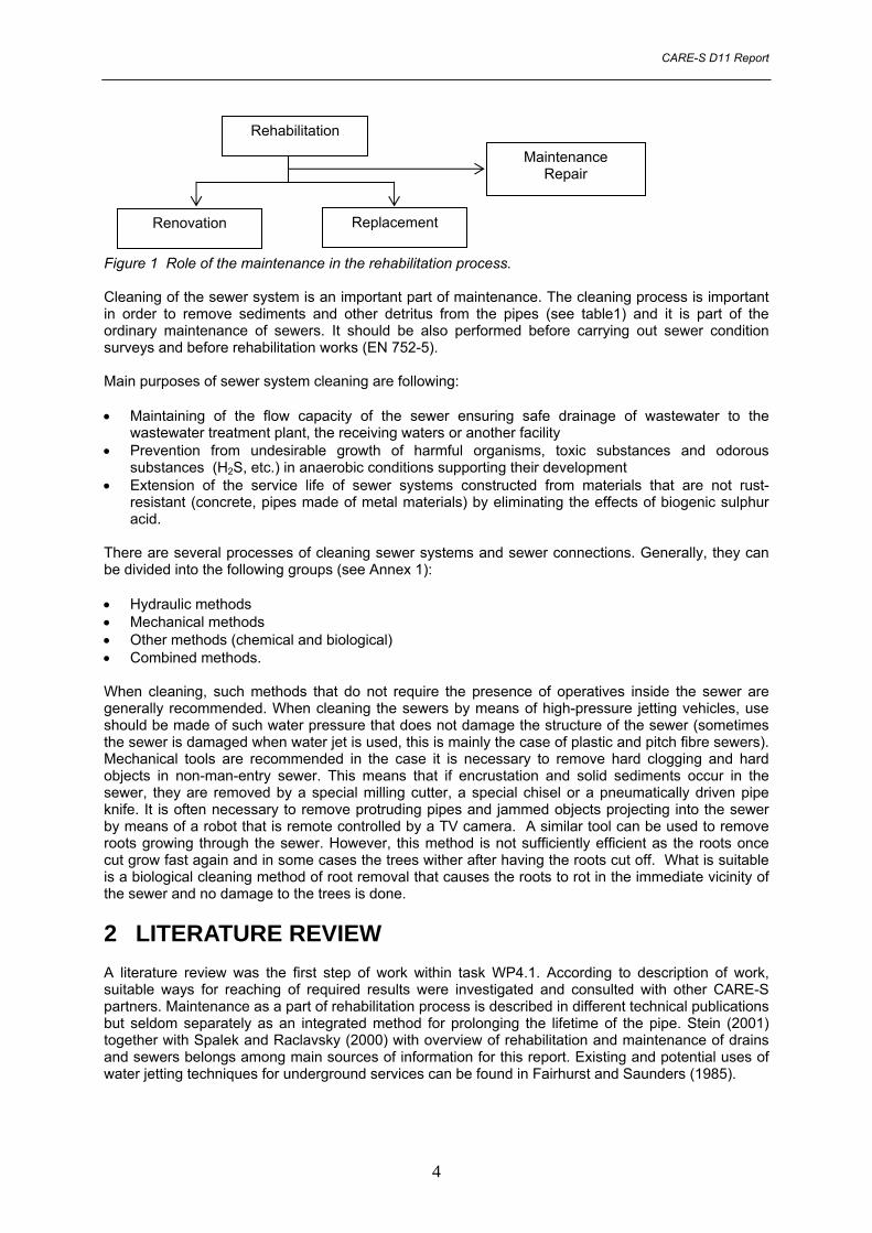
1.2 Role in the rehabilitation planning process The maintenance plays one of the most important roles in the rehabilitation process (See Figure 1) that means prolonging of the sewer lifetime, i.e. to postpone the rehabilitation and keep the sewer system in a good operational state. Maintenance and cleaning cover among other following: • inspection and investigation of structural and technical state of the sewer • cleaning of the sewer and its machinal equipment • removal of sediments, detritus and other obstacles, and small failures including small water-
proofing failures as well as causes of the failures • performance of small structural modifications and repairs • measurement of hydraulic loading of the sewer • removal of the sewer damage caused by other utility lines (water lines, gas pipes etc.) either under
or above ground and other interfaces
3
CARE-S D11 Report
Rehabilitation
Renovation
Maintenance Repair
Replacement
Figure 1 Role of the maintenance in the rehabilitation process. Cleaning of the sewer system is an important part of maintenance. The cleaning process is important in order to remove sediments and other detritus from the pipes (see table1) and it is part of the ordinary maintenance of sewers. It should be also performed before carrying out sewer condition surveys and before rehabilitation works (EN 752-5). Main purposes of sewer system cleaning are following: • Maintaining of the flow capacity of the sewer ensuring safe drainage of wastewater to the
wastewater treatment plant, the receiving waters or another facility • Prevention from undesirable growth of harmful organisms, toxic substances and odorous
substances (H2S, etc.) in anaerobic conditions supporting their development • Extension of the service life of sewer systems constructed from materials that are not rust-
resistant (concrete, pipes made of metal materials) by eliminating the effects of biogenic sulphur acid.
There are several processes of cleaning sewer systems and sewer connections. Generally, they can be divided into the following groups (see Annex 1): • Hydraulic methods • Mechanical methods • Other methods (chemical and biological) • Combined methods. When cleaning, such methods that do not require the presence of operatives inside the sewer are generally recommended. When cleaning the sewers by means of high-pressure jetting vehicles, use should be made of such water pressure that does not damage the structure of the sewer (sometimes the sewer is damaged when water jet is used, this is mainly the case of plastic and pitch fibre sewers). Mechanical tools are recommended in the case it is necessary to remove hard clogging and hard objects in non-man-entry sewer. This means that if encrustation and solid sediments occur in the sewer, they are removed by a special milling cutter, a special chisel or a pneumatically driven pipe knife. It is often necessary to remove protruding pipes and jammed objects projecting into the sewer by means of a robot that is remote controlled by a TV camera. A similar tool can be used to remove roots growing through the sewer. However, this method is not sufficiently efficient as the roots once cut grow fast again and in some cases the trees wither after having the roots cut off. What is suitable is a biological cleaning method of root removal that causes the roots to rot in the immediate vicinity of the sewer and no damage to the trees is done.
2 LITERATURE REVIEW A literature review was the first step of work within task WP4.1. According to description of work, suitable ways for reaching of required results were investigated and consulted with other CARE-S partners. Maintenance as a part of rehabilitation process is described in different technical publications but seldom separately as an integrated method for prolonging the lifetime of the pipe. Stein (2001) together with Spalek and Raclavsky (2000) with overview of rehabilitation and maintenance of drains and sewers belongs among main sources of information for this report. Existing and potential uses of water jetting techniques for underground services can be found in Fairhurst and Saunders (1985).
4
CARE-S D11 Report
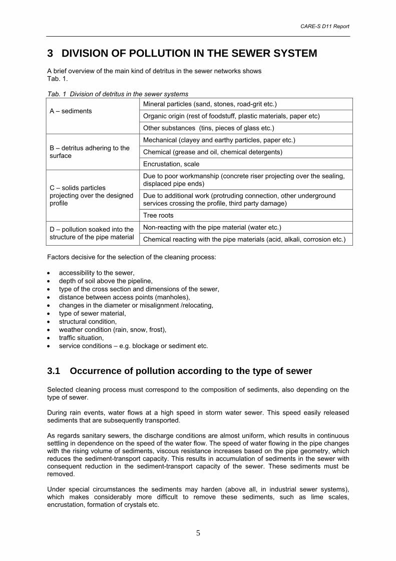
3 DIVISION OF POLLUTION IN THE SEWER SYSTEM A brief overview of the main kind of detritus in the sewer networks shows Tab. 1. Tab. 1 Division of detritus in the sewer systems
Mineral particles (sand, stones, road-grit etc.)
Organic origin (rest of foodstuff, plastic materials, paper etc) A – sediments
Other substances (tins, pieces of glass etc.)
Mechanical (clayey and earthy particles, paper etc.)
Chemical (grease and oil, chemical detergents) B – detritus adhering to the surface
Encrustation, scale
Due to poor workmanship (concrete riser projecting over the sealing, displaced pipe ends)
Due to additional work (protruding connection, other underground services crossing the profile, third party damage)
C – solids particles projecting over the designed profile
Tree roots
Non-reacting with the pipe material (water etc.) D – pollution soaked into the structure of the pipe material Chemical reacting with the pipe materials (acid, alkali, corrosion etc.)
Factors decisive for the selection of the cleaning process: • accessibility to the sewer, • depth of soil above the pipeline, • type of the cross section and dimensions of the sewer, • distance between access points (manholes), • changes in the diameter or misalignment /relocating, • type of sewer material, • structural condition, • weather condition (rain, snow, frost), • traffic situation, • service conditions – e.g. blockage or sediment etc.
3.1 Occurrence of pollution according to the type of sewer Selected cleaning process must correspond to the composition of sediments, also depending on the type of sewer. During rain events, water flows at a high speed in storm water sewer. This speed easily released sediments that are subsequently transported. As regards sanitary sewers, the discharge conditions are almost uniform, which results in continuous settling in dependence on the speed of the water flow. The speed of water flowing in the pipe changes with the rising volume of sediments, viscous resistance increases based on the pipe geometry, which reduces the sediment-transport capacity. This results in accumulation of sediments in the sewer with consequent reduction in the sediment-transport capacity of the sewer. These sediments must be removed. Under special circumstances the sediments may harden (above all, in industrial sewer systems), which makes considerably more difficult to remove these sediments, such as lime scales, encrustation, formation of crystals etc.
5
CARE-S D11 Report
3.2 Extraction of material from the pipelines If the flow rate rises, it is not possible to extract fully all material transported to the access point / manhole, which results in pollution of the next section of the pipeline. For this reason, the sewer system should always be cleaned from the upstream end down towards the wastewater treatment plant. The quality and velocity of cleaning depend on the power of pressurised water. As the pressure of flushing water must be limited to avoid damaging the pipe, higher efficiency may be achieved by increasing volume of flushing water. Cleaning frequency depends on the pipe gradient – in other words, on the settleability of sediments in the pipeline.
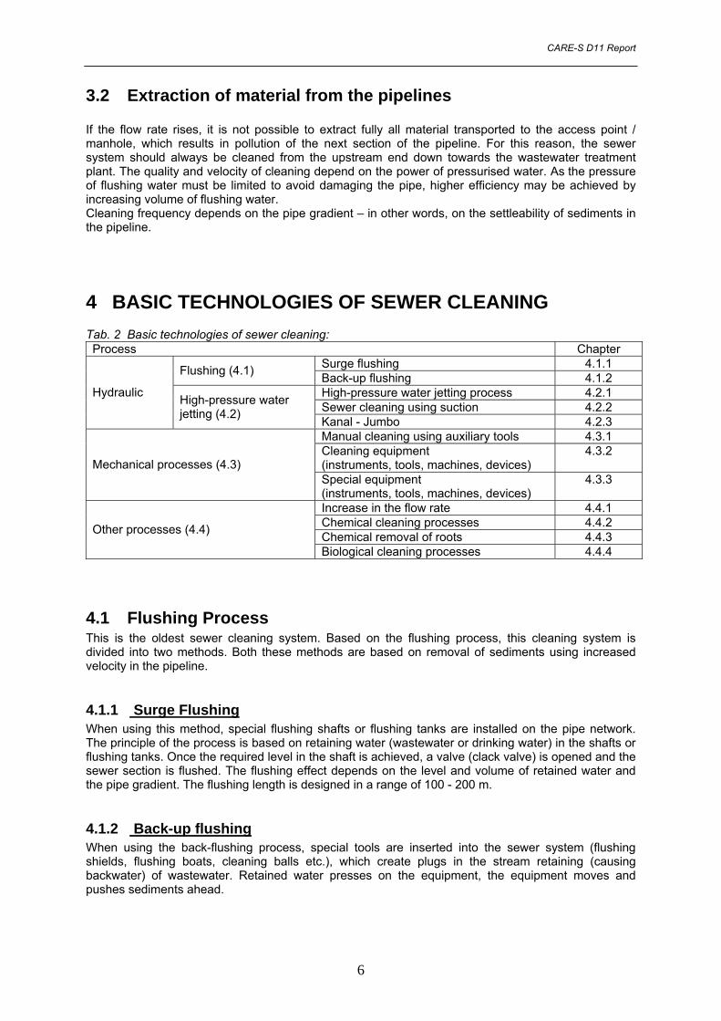
4 BASIC TECHNOLOGIES OF SEWER CLEANING Tab. 2 Basic technologies of sewer cleaning: Process Chapter
Surge flushing 4.1.1 Flushing (4.1) Back-up flushing 4.1.2 High-pressure water jetting process 4.2.1 Sewer cleaning using suction 4.2.2
Hydraulic High-pressure water jetting (4.2) Kanal - Jumbo 4.2.3
Special equipment (instruments, tools, machines, devices)
4.3.3
Increase in the flow rate 4.4.1 Chemical cleaning processes 4.4.2 Chemical removal of roots 4.4.3 Other processes (4.4)
Biological cleaning processes 4.4.4
4.1 Flushing Process This is the oldest sewer cleaning system. Based on the flushing process, this cleaning system is divided into two methods. Both these methods are based on removal of sediments using increased velocity in the pipeline.
4.1.1 Surge Flushing When using this method, special flushing shafts or flushing tanks are installed on the pipe network. The principle of the process is based on retaining water (wastewater or drinking water) in the shafts or flushing tanks. Once the required level in the shaft is achieved, a valve (clack valve) is opened and the sewer section is flushed. The flushing effect depends on the level and volume of retained water and the pipe gradient. The flushing length is designed in a range of 100 - 200 m.
4.1.2 Back-up flushing When using the back-flushing process, special tools are inserted into the sewer system (flushing shields, flushing boats, cleaning balls etc.), which create plugs in the stream retaining (causing backwater) of wastewater. Retained water presses on the equipment, the equipment moves and pushes sediments ahead.
6
CARE-S D11 Report
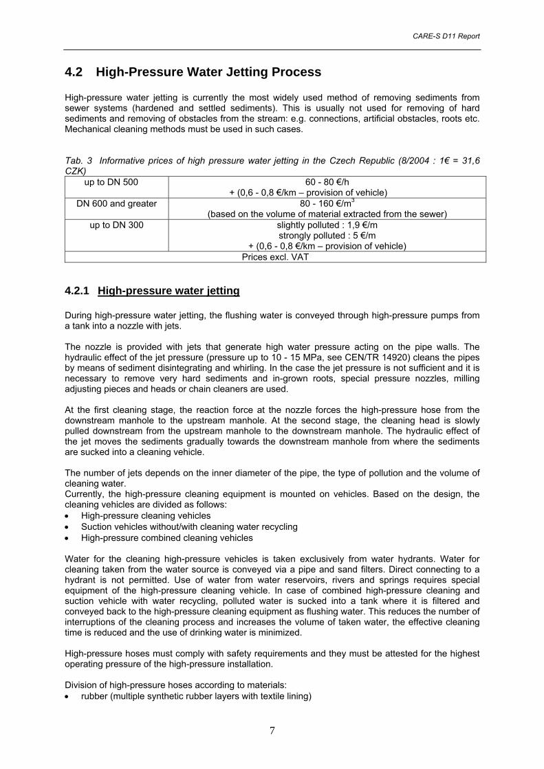
4.2 High-Pressure Water Jetting Process High-pressure water jetting is currently the most widely used method of removing sediments from sewer systems (hardened and settled sediments). This is usually not used for removing of hard sediments and removing of obstacles from the stream: e.g. connections, artificial obstacles, roots etc. Mechanical cleaning methods must be used in such cases. Tab. 3 Informative prices of high pressure water jetting in the Czech Republic (8/2004 : 1€ = 31,6 CZK)
up to DN 500 60 - 80 €/h + (0,6 - 0,8 €/km – provision of vehicle)
DN 600 and greater 80 - 160 €/m3
(based on the volume of material extracted from the sewer) up to DN 300 slightly polluted : 1,9 €/m
4.2.1 High-pressure water jetting During high-pressure water jetting, the flushing water is conveyed through high-pressure pumps from a tank into a nozzle with jets. The nozzle is provided with jets that generate high water pressure acting on the pipe walls. The hydraulic effect of the jet pressure (pressure up to 10 - 15 MPa, see CEN/TR 14920) cleans the pipes by means of sediment disintegrating and whirling. In the case the jet pressure is not sufficient and it is necessary to remove very hard sediments and in-grown roots, special pressure nozzles, milling adjusting pieces and heads or chain cleaners are used. At the first cleaning stage, the reaction force at the nozzle forces the high-pressure hose from the downstream manhole to the upstream manhole. At the second stage, the cleaning head is slowly pulled downstream from the upstream manhole to the downstream manhole. The hydraulic effect of the jet moves the sediments gradually towards the downstream manhole from where the sediments are sucked into a cleaning vehicle. The number of jets depends on the inner diameter of the pipe, the type of pollution and the volume of cleaning water. Currently, the high-pressure cleaning equipment is mounted on vehicles. Based on the design, the cleaning vehicles are divided as follows: • High-pressure cleaning vehicles • Suction vehicles without/with cleaning water recycling • High-pressure combined cleaning vehicles Water for the cleaning high-pressure vehicles is taken exclusively from water hydrants. Water for cleaning taken from the water source is conveyed via a pipe and sand filters. Direct connecting to a hydrant is not permitted. Use of water from water reservoirs, rivers and springs requires special equipment of the high-pressure cleaning vehicle. In case of combined high-pressure cleaning and suction vehicle with water recycling, polluted water is sucked into a tank where it is filtered and conveyed back to the high-pressure cleaning equipment as flushing water. This reduces the number of interruptions of the cleaning process and increases the volume of taken water, the effective cleaning time is reduced and the use of drinking water is minimized. High-pressure hoses must comply with safety requirements and they must be attested for the highest operating pressure of the high-pressure installation. Division of high-pressure hoses according to materials: • rubber (multiple synthetic rubber layers with textile lining)
7
CARE-S D11 Report
• plastic (seamless internal elastomer layer, textile lining, external layer e.g. PUR) Selection of the high-pressure hose profile (amount of flush water) corresponds to the following hose diameters: • Up to 200 l/min - DN 19 • Up to 325 l/min - DN 25 • Up to 650 l/min - DN 32 • Up to 800 l/min - DN 40 During transport of water in the high-pressure hose occurs friction resistance, which reduces the water pressure (high flow speed results in great decrease of pressure drop along the high-pressure hose). The length of hoses in standard vehicles ranges from 120 to 200 m. Special high-pressure vehicles are available on the market for special cleaning – the hose length is up to 800 m. Important parameters determining the type of working tools: • diameter of the cleaned sewer • type of sediments in the sewer • degree of sewer pollution • performance of the high-pressure hose (operating pressure and quantity of supplied water). Pre-conditions for efficient and effective sewer cleaning: • sufficient tensile (reactive) strength to drive the high-pressure hose and jets in the sewer • sufficient volume of flush water to transport (carry away) sediments towards the inspection
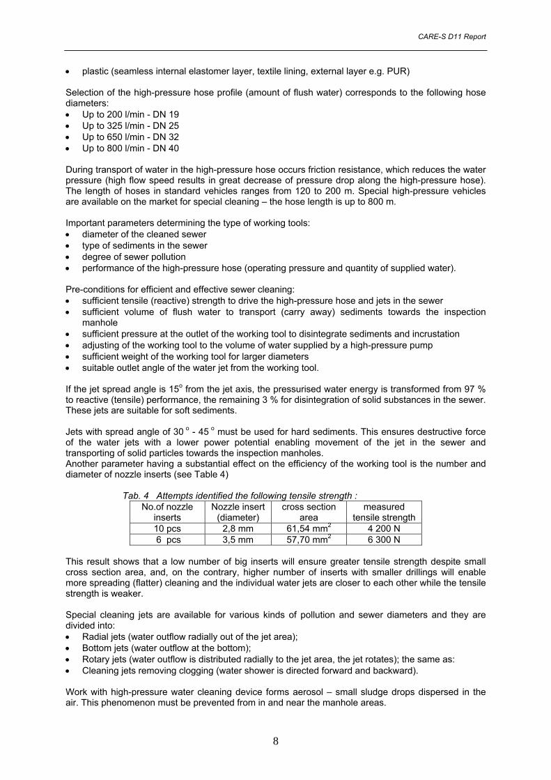
manhole • sufficient pressure at the outlet of the working tool to disintegrate sediments and incrustation • adjusting of the working tool to the volume of water supplied by a high-pressure pump • sufficient weight of the working tool for larger diameters • suitable outlet angle of the water jet from the working tool. If the jet spread angle is 15o from the jet axis, the pressurised water energy is transformed from 97 % to reactive (tensile) performance, the remaining 3 % for disintegration of solid substances in the sewer. These jets are suitable for soft sediments. Jets with spread angle of 30 o - 45 o must be used for hard sediments. This ensures destructive force of the water jets with a lower power potential enabling movement of the jet in the sewer and transporting of solid particles towards the inspection manholes. Another parameter having a substantial effect on the efficiency of the working tool is the number and diameter of nozzle inserts (see Table 4) Tab. 4 Attempts identified the following tensile strength :
No.of nozzle inserts
Nozzle insert (diameter)
cross section area
measured tensile strength
10 pcs 2,8 mm 61,54 mm2 4 200 N 6 pcs 3,5 mm 57,70 mm2 6 300 N
This result shows that a low number of big inserts will ensure greater tensile strength despite small cross section area, and, on the contrary, higher number of inserts with smaller drillings will enable more spreading (flatter) cleaning and the individual water jets are closer to each other while the tensile strength is weaker. Special cleaning jets are available for various kinds of pollution and sewer diameters and they are divided into: • Radial jets (water outflow radially out of the jet area); • Bottom jets (water outflow at the bottom); • Rotary jets (water outflow is distributed radially to the jet area, the jet rotates); the same as: • Cleaning jets removing clogging (water shower is directed forward and backward). Work with high-pressure water cleaning device forms aerosol – small sludge drops dispersed in the air. This phenomenon must be prevented from in and near the manhole areas.
8
CARE-S D11 Report
This can be also achieved by: • using a pendular jet for big man-entry profiles; • reducing the pump pressure about 10 m before the starting manhole (this sewer section should be
redone under a correct pressure as soon as the vehicle moves towards the next manhole in order to transport the extracted and loaded material) or
• covering the manhole by using a thin sheet metal or a plastic with entries for the high-pressure and suction hoses.
New development introduces a bottom cleaner with an integrated TV camera equipped with lighting. As a result of continuous monitoring of the cleaning process, the cleaning efficiency may be adjusted to the degree of pollution, whilst the volume of required cleaning water drops and the cleaning time is minimised. At the same time, the pipeline is inspected. The performance of the high-pressure cleaning machines with 2 operators may reach up to 2,000 – 3,000 m/day. When water heating is used for flushing, it is possible to work at temperatures down to minus 15°C. Polymers added to the flushing water reduce friction losses in the hose so that hoses with a length up to 800 m may be used for long sections (for example landfill drainage). Cleaning using high-pressure water cleaning process is economically advantageous in drainage and sewer systems up to about DN 2500. Clogging can be removed in many cases by selecting nozzles with additional jets on the front. In accessible areas and for special purposes it is possible to perform the cleaning by using a manually controlled high-pressure cleaning device while following all relevant safety precautions. 4.2.1.1 High-pressure cleaning in practice 4.2.1.1.1 Description of the sewer cleaning equipment Sewer cleaning equipment can be divided according to function into separate flushing equipment, separate suction equipment, combined equipment with water recycling (mechanical treatment of sucked in wastewater) and special equipment. • Separate flushing equipment Generally, it consists of storage and high-pressure equipment. It is used only to flush the sewer. Solid particles disintegrated by high-pressure cleaning are carried away downstream. This equipment is used mainly in smaller diameters (sewer connections) to unblock the outlet. • Separate suction equipment Suction equipment (suction vehicle) consisting of a vacuum system (vacuum pump) and a sludge chamber. The equipment sucks out (extracts) solid particles and polluted wastewater from the sewer. • Combined equipment This equipment provides both the functions above integrated in one vehicle. The combined vehicles cleaning sewer systems with both high-pressure and vacuum equipment are preferred these days. The cistern of the combined equipment is divided by a fixed partition wall or a removable piston to a chamber containing flush water and a sludge chamber storing solid particles. • Combined equipment with water recycling Compared to combined equipment defined under “Separate flushing equipment” item, this equipment includes wastewater treatment. Water used to clean the sewer is obtained by reverse mechanical treatment of sucked wastewater. This ensures ecological cleaning of the sewer system as there is no need to use drinking water for the flushing purposes. The wastewater treatment is multistage. It usually consists of various types of filters, screens, strainers and cyclone centrifuges. Automatic vacuum extraction of solid particles into the sludge chamber is used.
9
CARE-S D11 Report
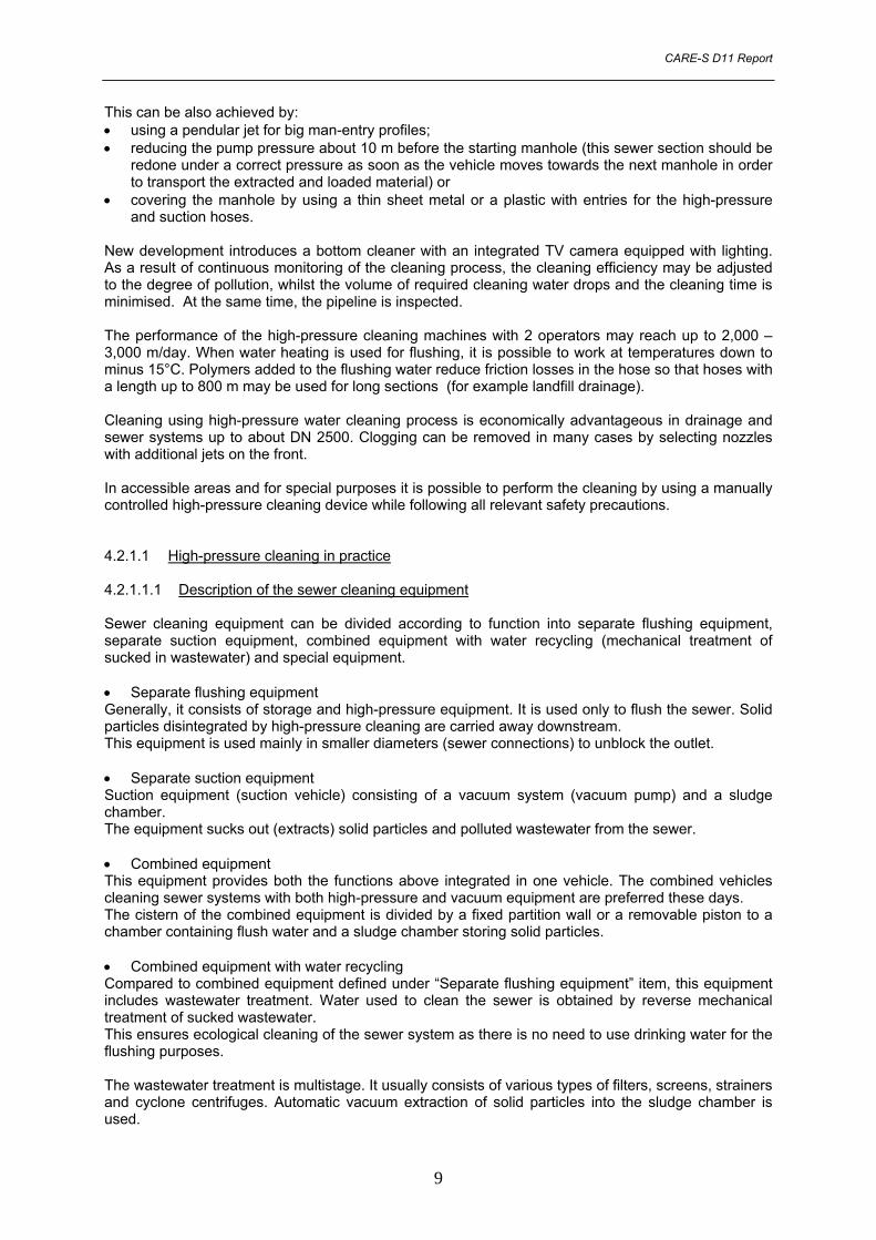
• Special equipment - special vehicles for grease disposal - system separating oil products from wastewater. 4.2.1.1.2 Operation of sewer cleaning equipment Basic parameters affecting the quality of sewer cleaning: • high-performance and correctly adjusted cleaning equipment • trained cleaning equipment operators • correct choice and use of working tools and high-pressure hoses. The higher the profile of the sewer and the degree of pollution, the higher amount of flush water must be supplied by the high-pressure pump. Informative values of the required volume of flush water needed for heavy jets are shown in the Tab. 5: Tab. 5 Values of the required volume of flush water needed for heavy jets
Volume of water (l/min.) Used in profiles (mm) 40 – 90 from DN 100 90 – 170 from DN 150 170 – 220 from DN 200 220 – 360 from DN 250
Water used for flushing must be pressurised in the high-pressure pump to 10MPa – 20MPa. This pressure must be reached at the outlet of the working tool. To determine the active pressure on the jet it is necessary to deducts all local losses and losses along the friction length in the high-pressure hose. The active water pressure at the outlet of the working tool ensures reactive movement of the working tool in the sewer forward, and destruction of sediments in the sewer. The movement of the working tool backward is ensured using the high-pressure hose hydraulic winder. In order to clean the sewer and to transport the cleaning equipment from one place to another when the temperatures are below zero it is necessary to equip the high-pressure system with certain accessories. In most cases these include various combinations of the following equipment: • pneumatic emptying of the whole high-pressure system • circulation pumps ensuring water circulation in the high-pressure system • heating of the high-pressure by thermal insulated boxes with additional heating • the cleaning system built in a thermal insulated heated superstructure. Short-term emergency situations during frost can be solved even using the equipment without winter accessories (the cleaning equipment must be transported to the place of emergency situation in an empty condition and the high-pressure system must be emptied again immediately after completion of the cleaning process). Long-term operations (conceptual sewer cleaning) at temperatures below minus 10o C are not usually performed (the jets get frozen, the sewer covers cannot be removed, etc.). 4.2.1.2 Damage caused by high-pressure water cleaning process Unprofessional application of high-pressure water cleaning may result in damage to the pipe in the form of grooves, cracks and holes in the pipe wall or the lining. The pipe may be damaged during the cleaning process as a result of: • impact of the nozzle; • turbulence of sediments or stones;
10
CARE-S D11 Report
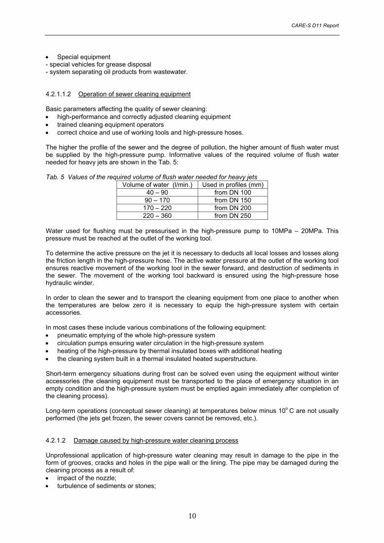
• jets working in the same spot. Loading of the pipe surface as a result of the jetting water depends on: • water pressure in the cleaning jet; • volume of water; • distance of the cleaning jet from the pipe wall; • number, size and outlet angle of the jet. When designing the operating parameters of the cleaning process it is necessary to consider: • pipe material; • wall thickness; • condition of the pipe. At present, no comprehensive standard dealing in detail with the issues of sewer system cleaning is available. The issue of high-pressure cleaning has been handled by the Underground Department in Zurich. The research results in the maximum values at which cement-asbestos, concrete, PVC and PE-HD sewers are not damaged, i.e. at a water pressure in the cleaning jet up to 12 MPa and a volume of 300 l/min. Similar results concerning high-pressure cleaning process have been achieved based on a research into the behaviour of a ductile cast iron pipe with a layer of cement coating. As regards pipelines provided with this type of coating and a coated layer of ≥ 6 mm and standard cleaning interval at the jet water pressure of < 17 MPa (measured at a high-pressure pump), with the age of 50 years, no damage expected when applying a high-pressure cleaning device was caused. Similar issues have been addressed in Hamburg at the department of Municipal Drainage since 1988. Tests were made using clear cases of accidents. In the first step limiting operating conditions on the construction site were analysed in dependence on the cross section and dimensions of the sewer and the maximum level of sediments, operating parameters for high-pressure cleaning processes were defined (see Tab. 6): • Type of the cleaning jet; • Water flow rate; • Quantity and diameter of jets; • Outlet angle; • Water pressure in the cleaning jet, etc. Tab. 6 Parameters of cleaning heads used for water high-pressure cleaning in the Hamburg sewers
Sections that must not be cleaned using high-pressure water were defined in individual cases. There are presently no guidelines or criteria governing testing of pipe sections with respect to their reaction to the high-pressure cleaning process. Corresponding investigation is usually conducted as part of special research programmes with a limited number of issues raised. This research is performed in stationary and non-stationary conditions using standard high-pressure cleaning vehicle with a maximum flow rate of about 350 l/min.
11
CARE-S D11 Report
4.2.1.3 Test methods for the resistance of sewer pipe according to CEN/TR 14920 Due to a low level of experience with the new developed test method applied to different materials and considering some aspects of reproducibility have not been proved, a European Standard is not feasible for the time being. Therefore CEN/TC 165 decided to give initial guidance to the market by publishing a test method as a Technical Report (CEN/TR). The test method specified in CEN/TR 14920 is intended to simulate the effect of high pressure cleaning on drains and sewers.
4.2.2 Sewer cleaning by suction In big man-entry sewers (diameter > about DN 1000) it is economical to suck the material out of the pipes based on the volume of water, type and amount of sediments. In order to do so, the operatives must be directly in the pipe and they must man-handle the nozzle of the suction hose. It is also necessary to be equipped with a sufficiently long suction hose and high-performance equipment with suction throughput over 2,000 m3/h. This cleaning process requires a minimum water flow rate (it must be re-pumped). Big pieces must be removed manually. The disadvantage of this cleaning process consists of the aforementioned restriction of the water flow rate to the minimum and relatively costly safety measures such as the use of ventilators, monitoring of the composition of the atmosphere and the potential use of various respirators. Requirements for the output of the vacuum equipment The amount and size of extracted solid particles and polluted wastewater depends mainly on the output of the exhauster and profile of the suction hose. Another important parameter is achieved pressure at the end of the suction hose. Informative values of the exhauster performance (not applicable to injectors) sucking solid particles through various profiles of the suction hose are shown in the Tab. 7: Tab. 7 Informative values of the exhauster performance
Profile of the suction hose Output of the extractor 100 mm from 800 m3/h 125 mm from 1 500 m3/h 150 mm from 3 000 m3/h
Note: The increasing output of the vacuum equipment must correspond to the size of the sludge chamber. Optimum proportion between the extractor outlet, profile of the suction hose and the size of the sludge chamber is very important mainly in relation to systems with continuous recycling of sucked wastewater. These parameters of the vacuum system must be adjusted to the output of the high-pressure pump (quantity of flush water delivered by the pump). The possibility of sucking wastewater from sewer system laid in a depth above 7 m is enabled by using of special auxiliary equipment. There are various types of end pieces of the suction hoses, enabling automatic or forced air sucking, which reduces the specific weight of the sucked medium.
4.2.3 Kanal-Jumbo This process eliminates the disadvantages of sucking because a high-performance, hydraulically driven pump is installed directly in the pipeline. A stone crusher and cloth ripper are installed before the pump. Nozzles and jets are directed towards the bottom according to the profile in order to whirl the sediments and create suspension. This entire unit mounted on a circular gear is pulled by a rope into the pipe from where it transports a mixture of water and released impurities to the surface via a suction hose DN 100. On the surface, the extracted material is separated from the water stream by using hydrocyclones, and the water is consequently re-used for cleaning purposes. This system operates fully independently. Kanal-Jumbo operates independently of the water level from 60 cm upwards. The advantages of this cleaning process consist mainly in the reduction of danger for the
12
CARE-S D11Report
operators, it does not load the wastewater treatment plant by increased volumes of flushing water and it is highly economical particularly in very big, deep pipelines and sewer systems with high water levels. The hydraulic liquid used does not harm the environment.
4.3 Mechanical cleaning Mechanical cleaning of pipe systems is one of the principal task of the operators in order to guarantee full design capacity of the pipe systems and full functioning of the water-related structures. Naturally, cleaned pipe system enables to make a thorough visual inspection of the condition of its inner surfaces, to choose the best technology eliminating all identified burst, it guarantees long-term service life and, last but not least, it minimises the costs of medium-term repair work and overhauls of the pipelines, it eliminates unscheduled closures and thus increase the cost-efficiency of their operation. Existing equipment for visual monitoring prior, during and after the cleaning enables to inspect pipes from DN 60. Mechanical cleaning is possible to disintegrate and remove sediments based on the type of sediments, incrustation and machines, distance between auxiliary entries in pipes starting from DN 25 mm. In principle, mechanical cleaning of pipe system can be divided into: • Manual cleaning using auxiliary tools; • Cleaning equipment (equipment, tools, machines, devices); • Special equipment (equipment, tools, machines, devices); • Other technologies and methods.
4.3.1 Manual cleaning using auxiliary tools It is limited by the size, skills, experience and equipment of the operators as well as by the relevant health and safety regulations. This concerns cleaning of • man-entry profiles from inwash and sediments. The working activities consist in disintegrating,
loading and transporting of these sediments. Tools include pick axes, pick hammers and blasting, tension-suspended scrapers and loading machines.
• incrustation-crystallic precipitates can also be removed from man-entry profiles based on the type of the pipe material and refurbishment method manually by manual grinding or sand blasting using high-pressure aggregates.
4.3.2 Cleaning using cleaning equipment This consists of several working stages and relevant equipment. • Firstly, the sediments and inwash is disintegrated and expanded • Secondly, this material is removed from the pipe profile, i.e. the sediments and inwash are
transported into or towards a shaft: - The equipment that pulls – sewer spirals, chains, sewer ploughs, scrapers (mainly for incrustation), sewer anchor, sewer bucket machine and loading machines, canal diggers, sewer scrapers, canal cleaning brushes, rubber circular brushes- arms. - The equipment with inserted metal spirals or pushing (in pressurized pipes) drills.
Based on the level of pollution and pipe diameter is it possible to use manual or motor-driven drills with a riving force of 5kN - 20 kN and potentially from 25 kN to 50 kN. These methods (technologies) bring very good results mainly in non-man-entry profiles. However, this work is demanding, it includes complicated pulling of ropes, hard manual work in unhygienic conditions with subsequent demanding and complicated extraction of the material from the shaft bottom using ropes and sewer bucket machines. Presently, suction vehicles are used to extract mud
13
CARE-S D11Report
and sludge from the shaft bottoms. Each water company has developed and implements various machines with different mechanization for this type of cleaning with corresponding success. These methods are presently not used in sections where there is heavy traffic above the sewer system.
4.3.3 Cleaning using special equipment In recent years, equipment achieving high level of cleaning, above all in small profiles has been developed and is used to remove hardened sediments projecting over connection pipes and artificial obstacles and roots. Based on the principle, they can be divided into following equipment: 4.3.3.1 Hammer equipment These include pipe core drills for circular pipes from DN 400 and egg-shaped profiles 200/300. Compressed air is used to drive the equipment and released sediments are carried in pressurized water and extracted from the shaft. Some equipment is fixed to the central rotary head by chains that release the sediments at a speed of 12,000 – 15,000 rev/min by impacts. The drive of the equipment is pneumatic or hydraulic. 4.3.3.2 Drilling and milling equipment – rotating This equipment is remote controlled and monitored by TV cameras in profiles DN 200 – 600. It is used to remove solid sediments and projecting outlets of connection branches and other obstacles in the profiles as well as roots. The equipment does not harm the pipe surface. It is led centrically and in individual cases it is equipped with a gradually adjustable milling head. The drive is hydraulic. 4.3.3.3 Drilling and milling equipment – rotating - hammering This category of equipment includes automatic blow drilling jets used to remove solid sediments from profiles between DN 100 - DN 1000 mm. High-pressure jetting flushing vehicle (with a pressure range of 8 – 10 MPa) should be used as the drive, the delivery of the suction pump is 250 – 450 l/min. The cleaning principle is the following. The jets ensure: • Movement to removal of the sediments; • Cleaning of the inner pipe or canal wall; • Transport of disintegrated sediments. The rotary and blow movement of the drilling equipment is driven by high-pressure water towards the front jets. The drilling equipment produces 1000 - 1500 impacts / min on the sediments and incrustation based on the working pressure and additional rotation (100 – 200 rev/min.) acts like a milling machine. The pressurised water used for the equipment is then used to flush the drill blade. Cutting knives made of hard metal fitted to a steel drilling head are used as the drilling tool corresponding to the sewer diameter. In the case when roots or other soft sediments penetrate, steel knives are used. For higher pipe diameters, use is made of jetting parts installed on a slide guiding the equipment at a constant distance from the pipe surface. The slide/skid allow for a wide range of adjustment. 4.3.3.4 Cutting equipment – mechanical Cutting equipment (instruments, tools, machines and devices) is used to level projecting outlets of connections and other artificial obstacles such as roots in pipes from DN 100 to 600 supervised by a TV camera. It is possible to distinguish between mechanical equipment and equipment based on pressure water jet.
14
CARE-S D11Report
Mechanical equipment includes the pipe saw robot – the saw movement forward and backward is supplemented by a rotation along the inner surface of the pipe. If a saw with watercooling is used, the water is also used as a cleaning and cooling medium. It is pneumatically fixed in the working place and only 1 mm projects; it is used in sewer from DN 200 to 600. Mechanical robots with their own drives and various and multiple operations: • root shears • clamping tongs • pneumatic hammer • saw made of hard metal. The equipment is remote controlled and it is applicable up to DN 250. There is of course special equipment removing roots from the pipes, which is based on a spring knife and which can be used in profiles between DN 100 and 400 with additional pressure jet. 4.3.3.5 Cutting equipment – high-pressure water jet Cutting equipment (instruments, tools, machines and devices) uses high-pressure water jet up to 80 MPa to cut all obstacles in continuous stream and to remove more extensive incrustation where mechanical removing is not sufficient in diameters between DN 100 and DN 900. The work is inspected by a TV camera. The high-pressure jet is located on a movable arm and a movable gear. Water demand is about 70 l/min. 4.3.3.6 Sand blasting equipment In order to achieve and create an especially high degree of perfect surface, mainly in metal pipes (steel cast iron), surface sand blasting is used. This equipment is produced for pipes between DN 60 and 1600.
4.4 Other technologies Among other technologies belong especially: • Increasing the flow rate by adding air or polymer • Chemical cleaning methods • Chemical removal of roots • Biological cleaning methods.
4.4.1 Increasing the flow rate by adding air or polymer This method is used for example in pressure sewer systems for its regular 2 – 4x daily cleaning from sediments or long-term irregular cleaning. Added air generates higher speed of the medium in the pipe and as a result the drifting speed increase. This is conditioned by creation of „pockets“ in the pipe axis, where the air creates small drops from closed water resulting in a water cylinder facilitating mixing of water and sediments. Recommend air velocity is 4 - 7 m/sec in a pipe with a gradient of 2 ‰ and air pressure 0.1 MPa. Another possibility of increasing the flow rate is addition of polymers. The benefit of the polymer means reduction of energy looses (impact on flow turbulence). At a minimum concentration (max 60 ppm) it is possible to reach velocity increase of 70 %. This increase does not only consist in the changed viscosity but also in reduced friction on the pipe surface. Increased drifting velocity is an advantage for transport of solid particles. Of course, it is necessary to assess the effect of polymers on water. These methods are used preferably to clean invested siphons and other narrow spaces.
15
CARE-S D11Report
4.4.2 Chemical cleaning methods These chemical methods are limited to pipes used in the chemical, oil and gas industries, above all for removal of incrustation. The following is assumed: • Chemical release of sediments • Resistance of the pipes to chemicals used for pipe cleaning • Absolute pipe water tightness. Cleaning agents include acids, lay and special dissolving agents. The suitable concentration is set by the specific situation in the pipe. Among the cleaning procedures belong especially the following: Filling, maintaining in motion, emptying of the pipe by chemical agents, closing between two cleaning pigs, neutralisation after cleaning and inspection of trace elements in the cleaning chemicals.
4.4.3 Chemical removal of roots Mechanical removal of roofs must be often repeated as the roots grow fast. An alternative solution is usage of herbicides in a water solution or in the form of foam. The foam is also suitable for connections and it is prepared in special devices. These foams are highly cohesive and adhere to the walls and cavities in the pipes and their transformation to vapours are absorbed by the roots, which results in their rotting after about 4 – 20 weeks based on the concentration and contact time. Their effect lasts up to two years. Plant roots can be treated using biological-septic agents, but their use remains sporadic.
4.4.4 Biological cleaning methods The biological cleaning technologies are used firstly for removal of grease and fibres from the sewer surface, secondly for removal of residues and sediments containing phenols, proteins and mineral oils and thirdly for removal or suppressing of odours. There are several components used in hospitals, canteens and food-processing plants. The first component is liquid and consists of fatty acids and urea. This liquid is poured into drains and seal-pipe. The pipe system is filled up and hot water is added. After certain period, about 6 hours, components containing microorganisms are added. Another method consists in injecting of Sphaerotilus bacteria into sewage water. The bacteria are left in the water for three months. The sewer cleaning technology using bacteria is popular especially in USA (for example, in Washington DC, the savings reach amount up to 65% of the costs of cleaning).
16
CARE-S D11Report
5 FREQUENCY OF SEWER CLEANING Sewer system cleaning is one of the basic duties of the sewer operators. Main reasons and purpose of sewer cleaning were described in the introductory chapter - maintaining of the flow capacity, prevention from undesirable growth of harmful organisms and extension of the service life. Regular cleaning is maintenance method ensuring adequate wastewater disposal preventing from ecological problems having adverse impacts on the environment. The sewer system operator is obliged to ensure cleaning of each section of the sewer system once in 1 – 5 years. Regular cleaning in rated intervals is recommended for small diameters, while in case of large diameters it is possible to measure height of sediments and consequently clean the sewer when defined limit value (e.g. level of connection inlets) is reached.
6 SUMMARY Conclusive report D11 is part of task 4.1 – “Operational options” and provides an integrated overview of basic technologies for sewer cleaning as alternative possibilities to common rehabilitation including renovation, replacement and repair in order to for prolonging lifetime of sewers. Main technologies, their range of usage and applicability for particular kind of pollution or failure and conditions limiting field of application are described and explained.
7 REFERENCES Ahrens, J. F., Leonhard, O. A., Townley, N. R. (1970) Chemical Control of Tree Roots in Sewer Lines. Journal Water Pollution Control Federation. Brune, P. (1990) Verhalten von Tonerdezementmörtelauskleidungen in Rohren aus duktilem Gusseisen bei der Beanspruchung mit Hochdruckreinigungsgeräten. Fachgemeinschaft Gusseiserne Rohre, FGR-Gussrohrtechnik No. 23. CEN/TR 14920 Jetting resistance of drain and sewer pipes - Moving jet test method Čištění kanalizací, Standard, DOS-T, ČKAIT EN CSN 13508-2 Conditions of drain and sewer systems outside buildings - Part 2: Visual inspection coding system Esterková, M. a kol. Bezvýkopová obnova podzemních vedení, GAS s.r.o., Praha Fairhurst, R. M., Saunders, D.M. (1985) Water jetting techniques - existing and potential uses for underground services. First International Conference and Exhibition on Trenchless Construction for Utilities, London. Gale, J. (1981) Sewer Renovation. Technical Report TR 87 A, Water Research Centre (WRC), Swindon Hochstrate, K., Jansen, K. (1996) Wertehaltung und Finanzierung von Abwasserkanalnetzen durch vorbeugende Instandhaltung. Korrespondenz Abwasser (KA) 43, No. 2. Information of the City of Hamburg, Baubehörde - Hauptabteilung Stadtentwässerung. Klepsatel, F. a kol. Bezvýkopová výstavba podzemních vedení, GAS s.r.o., Praha Krejčí, V. a kol. (2002) Odvodnění urbanizovaných území - koncepční přístup (Urban drainage – integrated assessment), NOEL 2000, Brno, ISBN 80-86020-39-8. Kupczik, G. (1987) Sielwolf-Verfahren zur Reinigung grossvolumiger Abwasserkanäle. Documentation 1st International Conference on Pipeline Construction, Hamburg. Lenz, J., Wielenberg, M., Grüss, D. (1996) Reinigung von Abwasserkanälen durch Hochdruckspülung. Vulkan, Essen Operation and Maintenance of Wastewater Collection Systems (1985) Manual of Practice No. 7, Water Pollution Control Federation, Washington Schrock, J. (1984) Pipeline Rehabilitation Techniques. International Conference on the Planing, Construction, Maintenance & Operation of Sewerage Systems, Reading, England. Paper B4. Sewerage Rehabilitation Manual. Water Research Centre, Swindon 1983
17
CARE-S D11Report
Sieber, H.-U. (1981) Die Inkrustation und Sedimentation in Staumauer - Entwässerungsleitungen und Verfahren zur Regenerierung der Entwässerungssysteme. Wasserwirtschaft und Wasertechnik (WWT) 31, No. 6. Spalek, P. and Raclavsky.J. (2000) Sanace stok a kanalizačních přípojek. Technické doporučení SOVAK, Praha - Hydroprojekt Praha a.s. , 2002 Standardleistungsbuch für das Bauwesen (StLB) Bauen im Bestand (BiB). Leistungsbereich 309 - Reinigung und Inspektion von Abwasserkanälen und -leitungen (11.96) Stein, D. (1999) Instandhaltung von Kanalisationen, Ernst a Sohn Verlag, Berlin, ISBN 3-433-01315-2 Stein, D. (2001) Rehabilitation and Maintenance of Drains and Sewers, Ernst a Sohn Verlag, Berlin, ISBN 3-433-01316-0 Störner, S. (1996) Richtlinien für die Kanalreinigung. Korrespondenz Abwasser (KA), No. 1. Störner, S., Larsson, B. (1990) Einfluss von Kanalreiningungsmundstücken auf das Reinigungsergebnis mit Hochdruckspülern. Korrespondenz Abwasser (KA) 37, No. 11. Townley, N. R. (1973) Chemical Control of Roots. Research Report, Sacramento Country Department of Public Works, Water Quality Division Trade web sites: http://www.aaras.de/index_frameset.html http://www.kanal-reinigung.de/ http://www.kmg.de http://www.ruhrnet.de/Hydrotechnik/d/index_d.htm (Paikert) http://www.woma.gb.com/
18
CARE-S D11Report
8 ANNEX 1
19
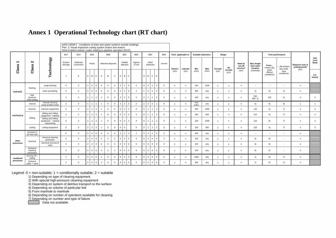
Annex 1 Operational Technology chart (RT chart)
prEN 13508-2 Conditions of drain and sewer systems outside buildings Part 2: Visual inspection coding system Drains and sewers Kind of defect solved: codes relating to pipeline operation (0/1/2)
BAF BAH BBA BBB BBC BBD BBE BBH Tech. applicable to Suitable diameters Shape Tech performance
1) Depending on type of clearing equipment 2) With special high-pressure cleaning equipment 3) Depending on system of detritus transport to the surface 4) Depending on volume of particular link 5) From manhole to manhole 6) Depending on number of operators available for cleaning 7) Depending on number and type of failure Data not available