Structure loaded by the seismicity effects Daniel Makovička, Assoc. Prof., D.Sc., C.E. Czech Technical University in Prague, Klokner Institute, CZ-166 08 Praha 6, Šolínova 7, Czech Republic, E/mail: [email protected]& Daniel Makovička, C.E. Static and Dynamic Consulting, CZ-284 00 Kutná Hora, Šolínova 7, Czech Republic, E/mail: [email protected]
Transcript
Structure loaded by the seismicity effects
Daniel Makovička, Assoc. Prof., D.Sc., C.E.
Czech Technical University in Prague, Klokner Institute,
1) Principles of earthquake analysis Example of a ventilation stack of a reactor building
2) Comparison of earthquake and other loading effects Cooling tower under combination of design loading states
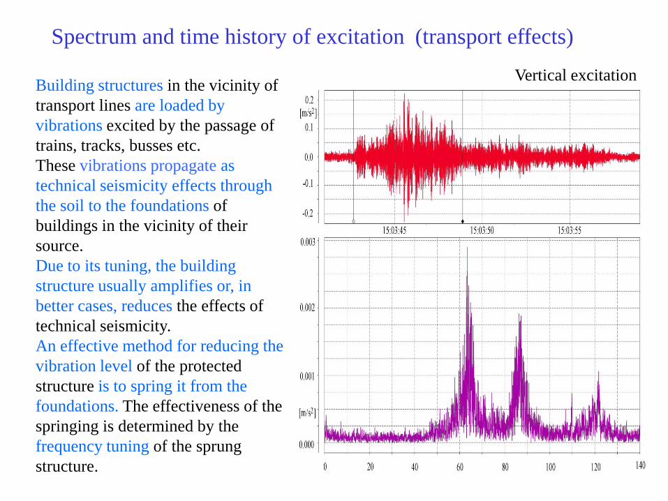
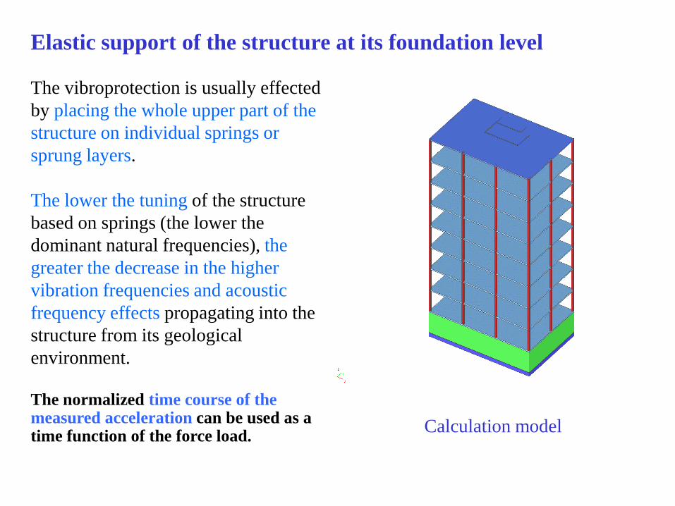
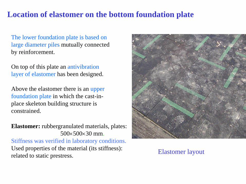
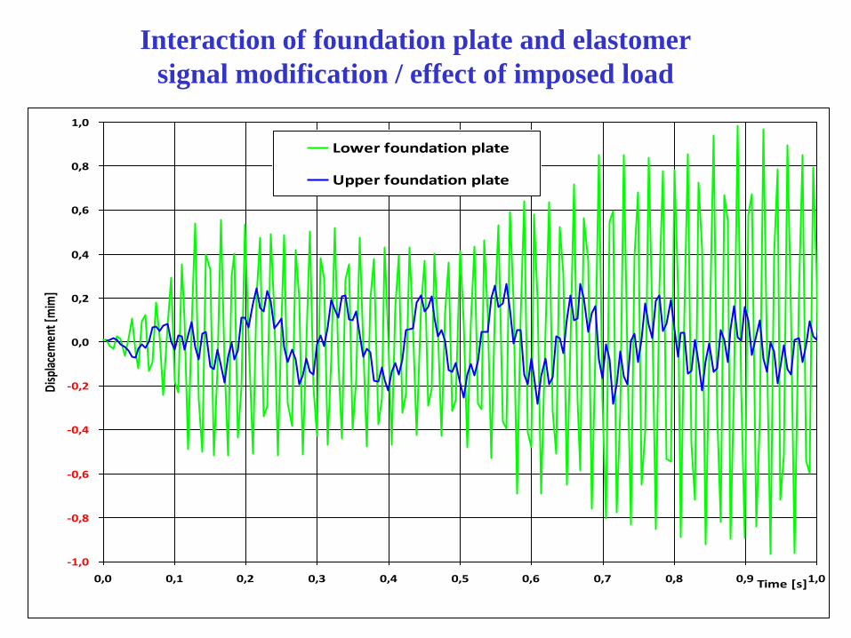
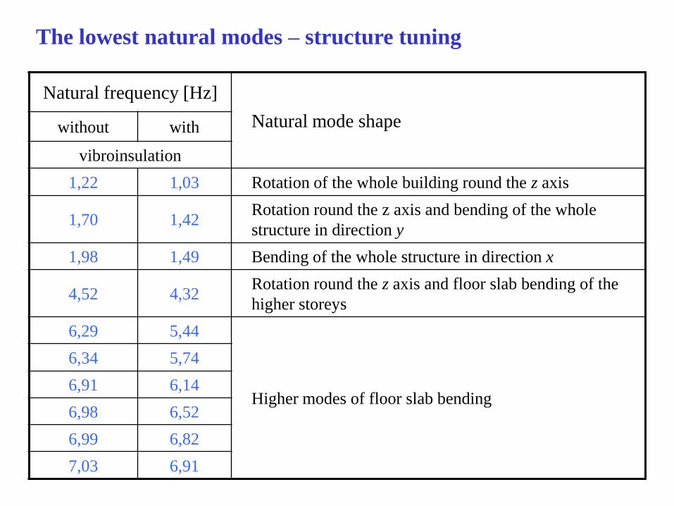
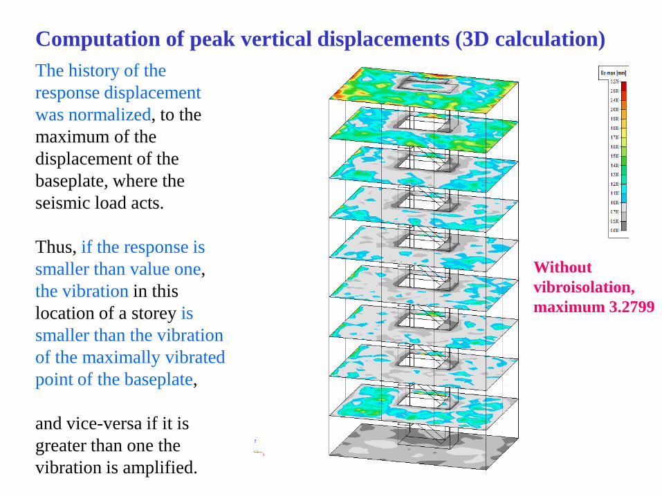
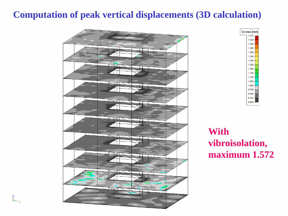
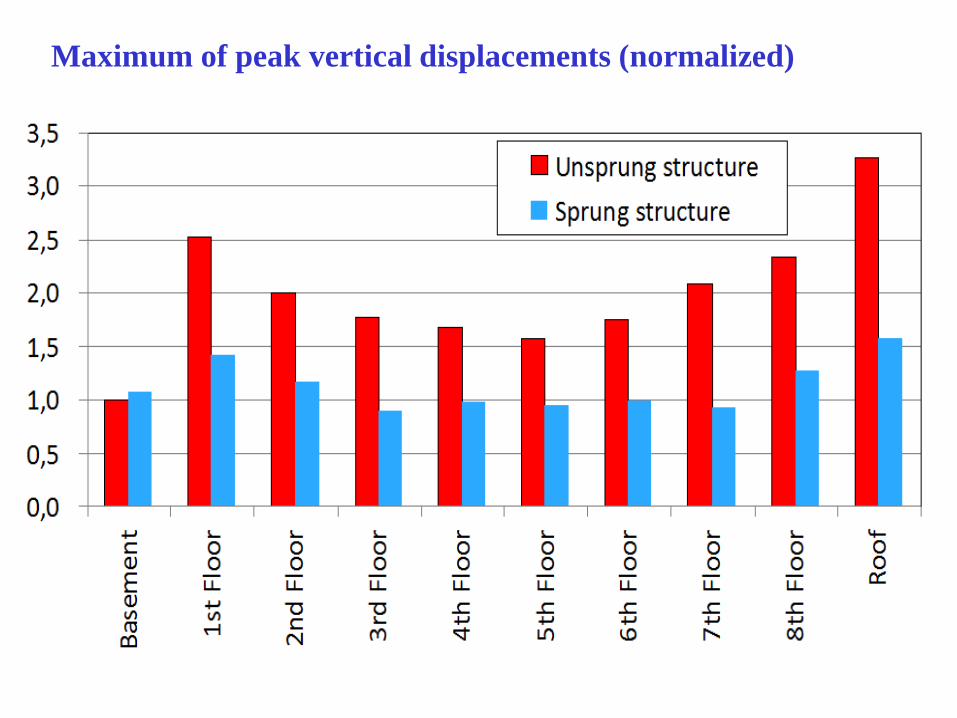
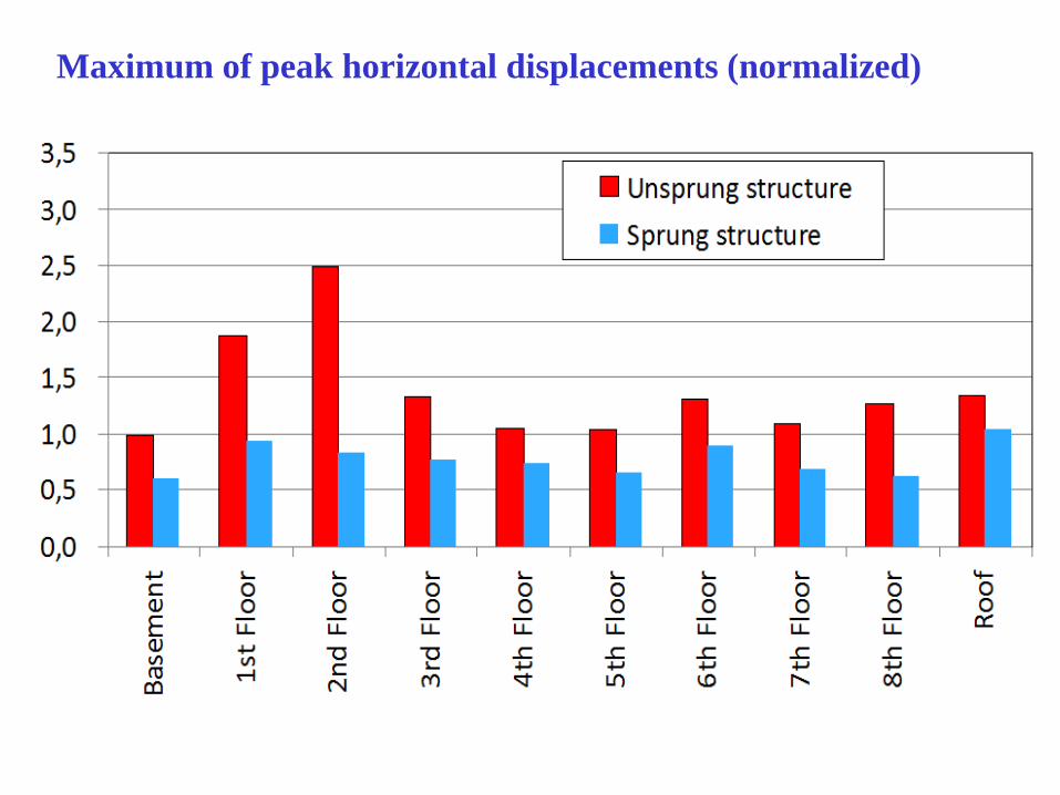
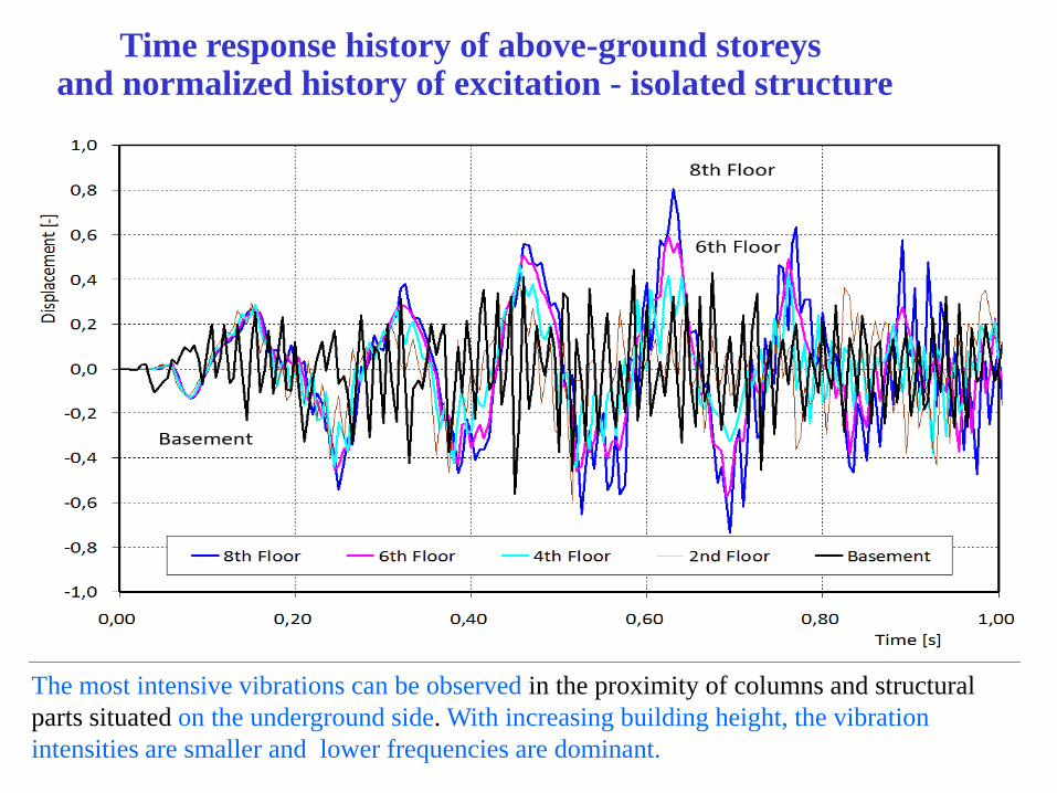
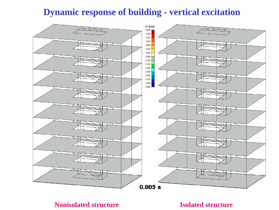
3) Vibrobase isolation of building
Example of administrative building
(1) Seismic resistance of a ventilation stack
of a reactor building
NPP Temelin – A case study
The goal of the paper:
the methodology of the simplified numerical earthquake analysis of the structure,
the response of the very sensitive structure to seismic loads (the spectrum of the lowest natural frequencies corresponds with the frequency spectrum of excitation),
the participation of individual response frequency components in the overall stress and strain state,
comparison of the recommendations of relevant standards and codes.
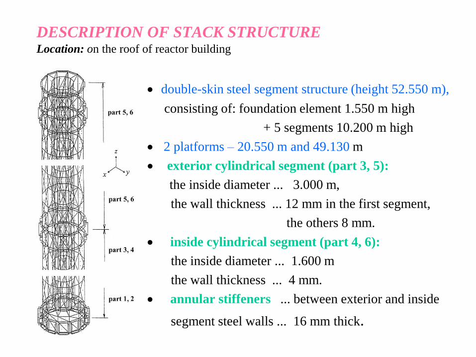
DESCRIPTION OF STACK STRUCTURE Location: on the roof of reactor building
double-skin steel segment structure (height 52.550 m),
consisting of: foundation element 1.550 m high
+ 5 segments 10.200 m high
2 platforms – 20.550 m and 49.130 m
exterior cylindrical segment (part 3, 5):
the inside diameter ... 3.000 m,
the wall thickness ... 12 mm in the first segment,
the others 8 mm.
inside cylindrical segment (part 4, 6):
the inside diameter ... 1.600 m
the wall thickness ... 4 mm.
annular stiffeners ... between exterior and inside
segment steel walls ... 16 mm thick.
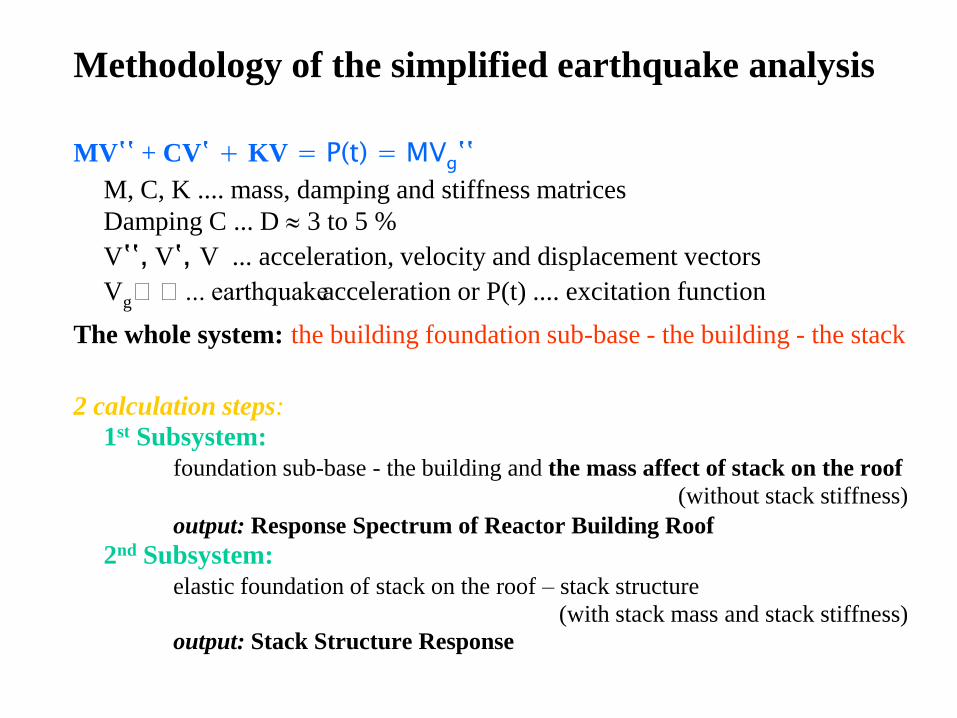
Methodology of the simplified earthquake analysis
MVʽʽ + CVʽ + KV = P(t) = MVgʽʽ
M, C, K .... mass, damping and stiffness matrices
Damping C ... D 3 to 5 %
Vʽʽ, Vʽ, V ... acceleration, velocity and displacement vectors Vgʽʽ... earthquake acceleration or P(t) .... excitation function
The whole system: the building foundation sub-base - the building - the stack
2 calculation steps:
1st Subsystem:
foundation sub-base - the building and the mass affect of stack on the roof
(without stack stiffness)
output: Response Spectrum of Reactor Building Roof
2nd Subsystem:
elastic foundation of stack on the roof – stack structure
(with stack mass and stack stiffness)
output: Stack Structure Response
The degree of justification
of the application of simplification methodology
The solution accuracy depends
– on the difference between the natural frequencies of the
stack and the natural frequencies of the building as a
whole structure;
– on the roof structure natural bending mode
(the top of building where the stack is anchored.
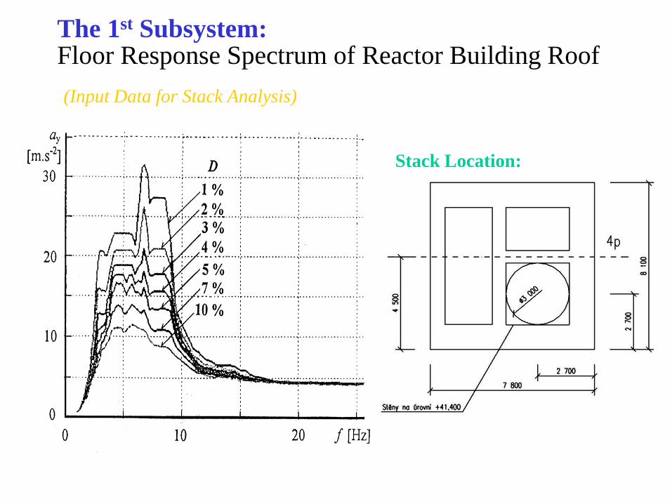
The 1st Subsystem: Floor Response Spectrum of Reactor Building Roof
(Input Data for Stack Analysis)
Stack Location:
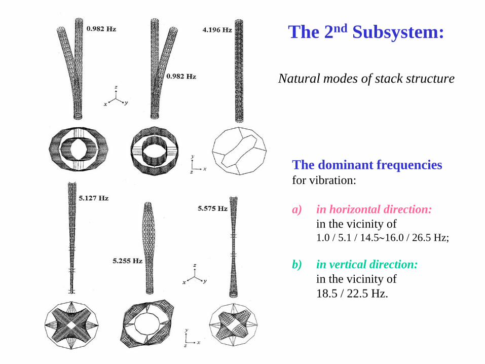
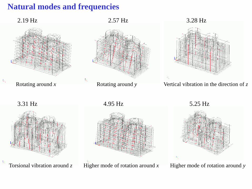
The 2nd Subsystem:
Natural modes of stack structure
The dominant frequencies
for vibration:
a) in horizontal direction:
in the vicinity of 1.0 / 5.1 / 14.516.0 / 26.5 Hz;
b) in vertical direction:
in the vicinity of
18.5 / 22.5 Hz.
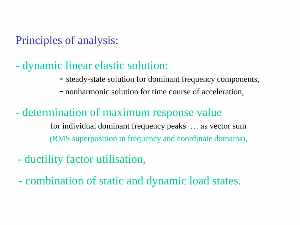
Principles of analysis: - dynamic linear elastic solution: - steady-state solution for dominant frequency components,
- nonharmonic solution for time course of acceleration,
- determination of maximum response value for individual dominant frequency peaks … as vector sum
(RMS superposition in frequency and coordinate domains),
- ductility factor utilisation,
- combination of static and dynamic load states.
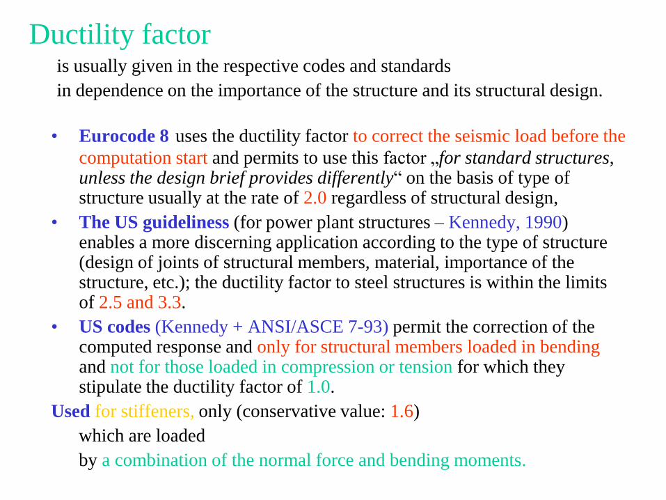
Ductility factor is usually given in the respective codes and standards
in dependence on the importance of the structure and its structural design.
• Eurocode 8 uses the ductility factor to correct the seismic load before the
computation start and permits to use this factor „for standard structures, unless the design brief provides differently“ on the basis of type of structure usually at the rate of 2.0 regardless of structural design,
• The US guideliness (for power plant structures – Kennedy, 1990) enables a more discerning application according to the type of structure (design of joints of structural members, material, importance of the structure, etc.); the ductility factor to steel structures is within the limits of 2.5 and 3.3.
• US codes (Kennedy + ANSI/ASCE 7-93) permit the correction of the computed response and only for structural members loaded in bending and not for those loaded in compression or tension for which they stipulate the ductility factor of 1.0.
Used for stiffeners, only (conservative value: 1.6)
which are loaded
by a combination of the normal force and bending moments.
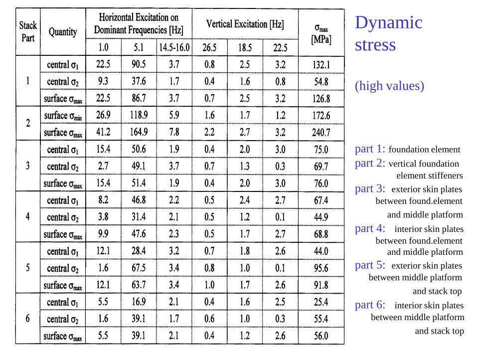
Dynamic
stress
(high values)
part 1: foundation element
part 2: vertical foundation
element stiffeners
part 3: exterior skin plates
between found.element
and middle platform
part 4: interior skin plates
between found.element
and middle platform
part 5: exterior skin plates
between middle platform
and stack top
part 6: interior skin plates
between middle platform
and stack top
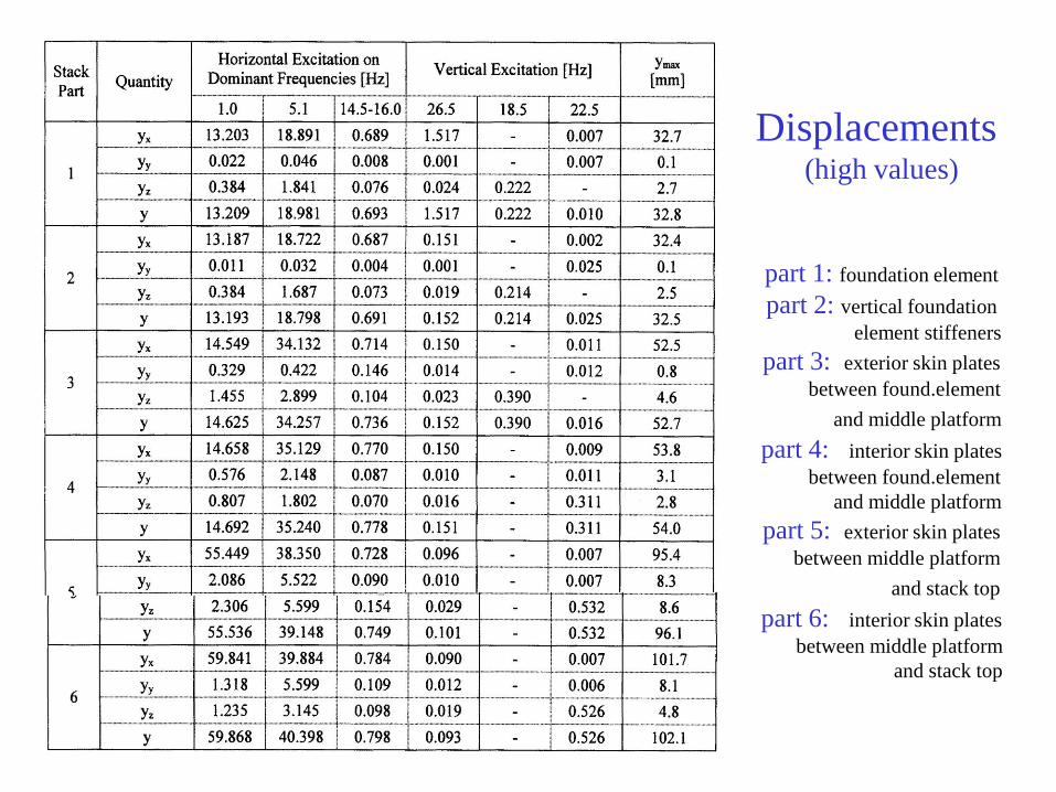
Displacements (high values)
part 1: foundation element
part 2: vertical foundation
element stiffeners
part 3: exterior skin plates
between found.element
and middle platform
part 4: interior skin plates
between found.element
and middle platform
part 5: exterior skin plates
between middle platform
and stack top
part 6: interior skin plates
between middle platform
and stack top
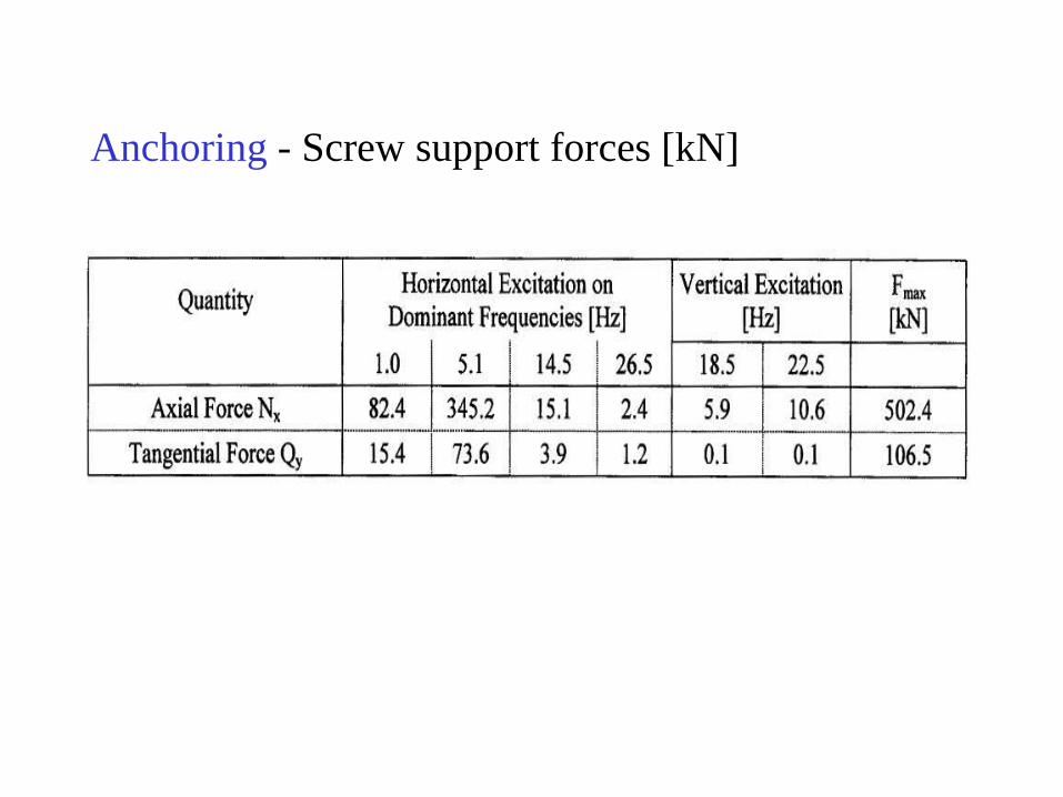
Anchoring - Screw support forces [kN]
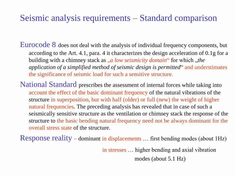
Seismic analysis requirements – Standard comparison
Eurocode 8 does not deal with the analysis of individual frequency components, but
according to the Art. 4.1, para. 4 it characterizes the design acceleration of 0.1g for a
building with a chimney stack as „a low seismicity domain“ for which „the
application of a simplified method of seismic design is permitted“ and understimates
the significance of seismic load for such a sensitive structure.
National Standard prescribes the assessment of internal forces while taking into
account the effect of the basic dominant frequency of the natural vibrations of the
structure in superposition, but with half (older) or full (new) the weight of higher
natural frequencies. The preceding analysis has revealed that in case of such a
seismically sensitive structure as the ventilation or chimney stack the response of the
structure to the basic bending natural frequency need not be always dominant for the
overall stress state of the structure.
Response reality – dominant in displacements … first bending modes (about 1Hz)
in stresses … higher bending and axial vibration
modes (about 5.1 Hz)
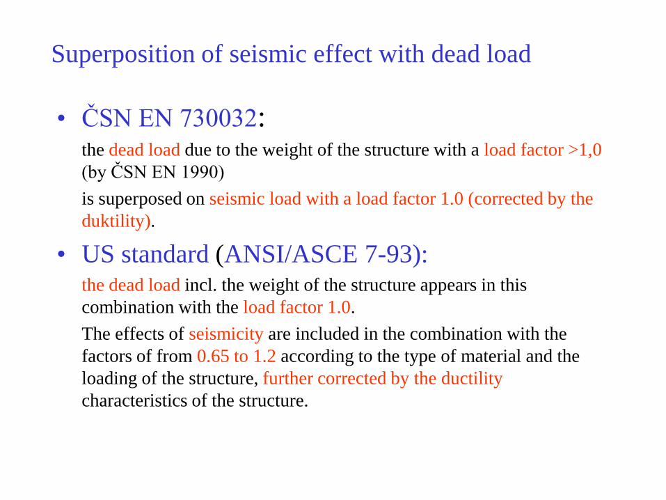
Superposition of seismic effect with dead load
• ČSN EN 730032: the dead load due to the weight of the structure with a load factor >1,0
(by ČSN EN 1990)
is superposed on seismic load with a load factor 1.0 (corrected by the
duktility).
• US standard (ANSI/ASCE 7-93): the dead load incl. the weight of the structure appears in this
combination with the load factor 1.0.
The effects of seismicity are included in the combination with the
factors of from 0.65 to 1.2 according to the type of material and the
loading of the structure, further corrected by the ductility
characteristics of the structure.
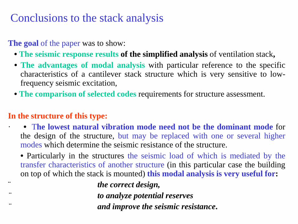
Conclusions to the stack analysis
The goal of the paper was to show:
• The seismic response results of the simplified analysis of ventilation stack,
• The advantages of modal analysis with particular reference to the specific characteristics of a cantilever stack structure which is very sensitive to low-frequency seismic excitation,
• The comparison of selected codes requirements for structure assessment.
In the structure of this type:
· • The lowest natural vibration mode need not be the dominant mode for the design of the structure, but may be replaced with one or several higher modes which determine the seismic resistance of the structure.
• Particularly in the structures the seismic load of which is mediated by the transfer characteristics of another structure (in this particular case the building on top of which the stack is mounted) this modal analysis is very useful for:
¨ the correct design,
¨ to analyze potential reserves
¨ and improve the seismic resistance.
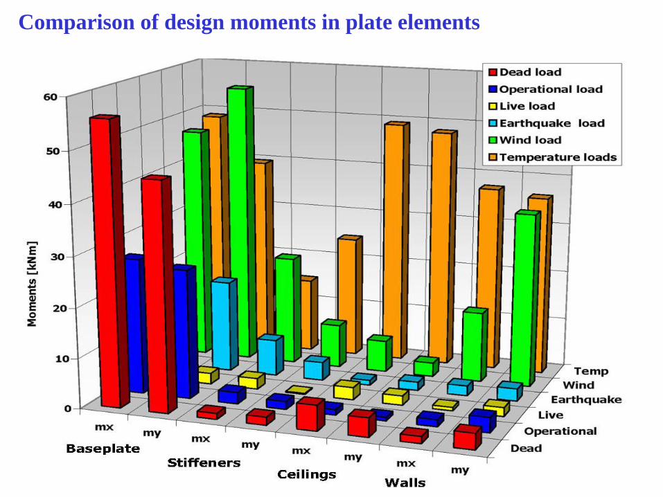
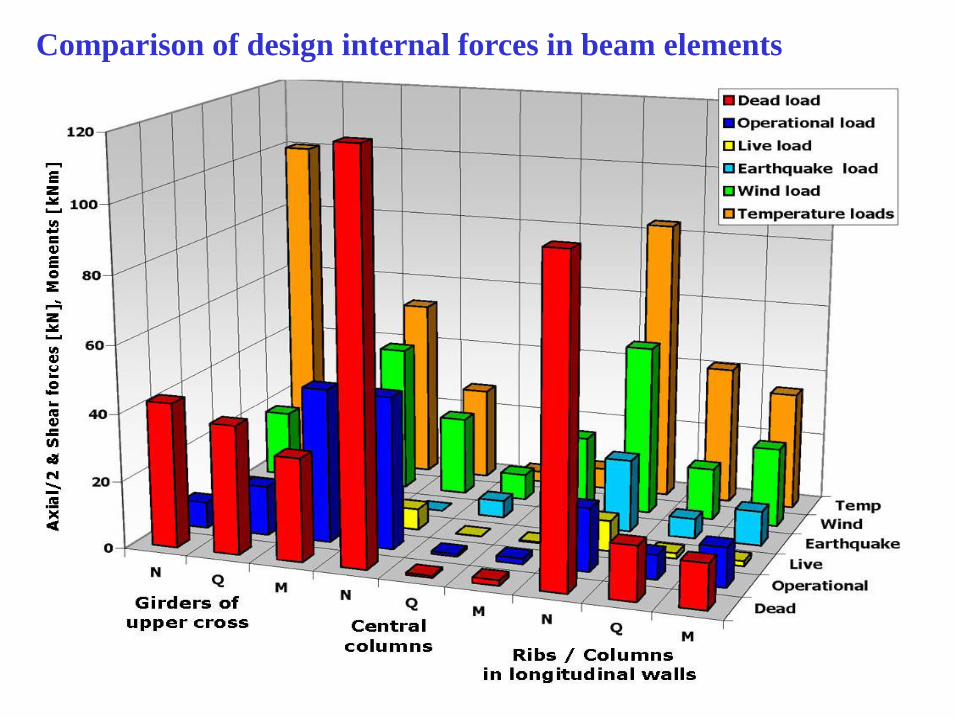
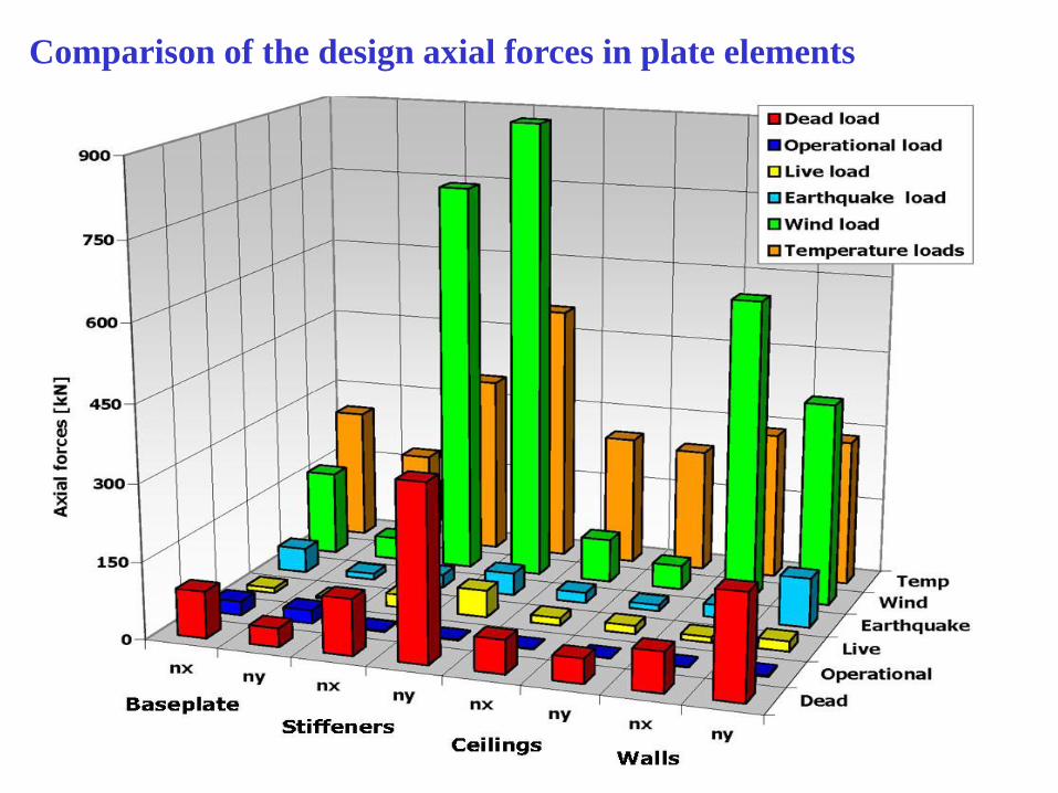
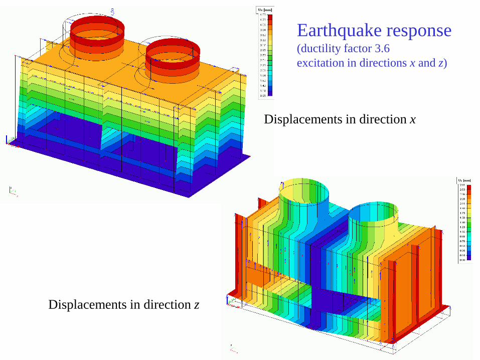
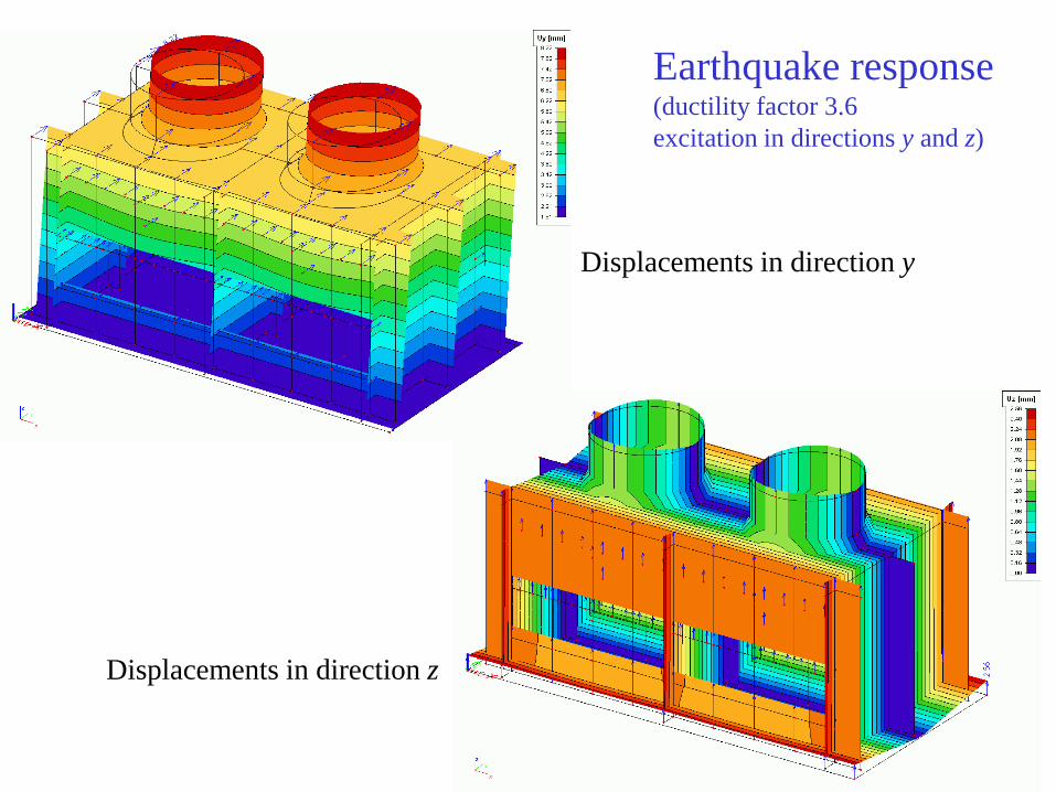
(2) Comparison of earthquake and other
loading effects
Cooling tower under combination of
design load states
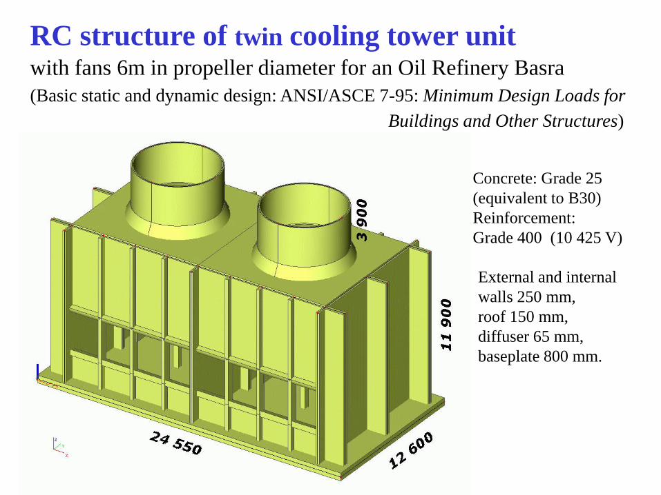
RC structure of twin cooling tower unit
with fans 6m in propeller diameter for an Oil Refinery Basra
(Basic static and dynamic design: ANSI/ASCE 7-95: Minimum Design Loads for
Buildings and Other Structures)
Concrete: Grade 25
(equivalent to B30)
Reinforcement:
Grade 400 (10 425 V)
External and internal
walls 250 mm,
roof 150 mm,
diffuser 65 mm,
baseplate 800 mm.
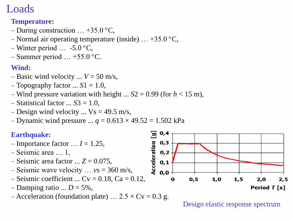
Loads Temperature:
– During construction … +35.0 C,
– Normal air operating temperature (inside) … +35.0 C,
– Winter period … -5.0 C,
– Summer period … +55.0 C.
Wind:
– Basic wind velocity ... V = 50 m/s,
– Topography factor ... S1 = 1.0,
– Wind pressure variation with height ... S2 = 0.99 (for h < 15 m),


![John Virapen - Vedlejsi Priznaky Smrt - Priznani Pharma Insajdera --- Side Effects- Death- Confessions of a Insider]](https://static.dokumenty.site/doc/80x56/55720583497959fc0b8b720d/john-virapen-vedlejsi-priznaky-smrt-priznani-pharma-insajdera-side-effects-death-confessions-of-a-insider.jpg)


![Pyrazolopyrimidinové inhibitory CDK · The experimental part of diploma thesis is focused on biological effects of two new pyrazolo[4,3-d]pyrimidine CDK inhibitors in the HCT-116](https://static.dokumenty.site/doc/80x56/5fda3b1606c824221e00cfdd/pyrazolopyrimidinov-inhibitory-cdk-the-experimental-part-of-diploma-thesis-is.jpg)


