60
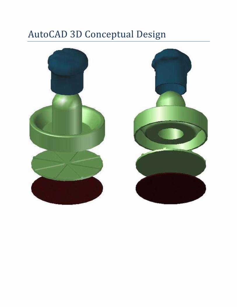
AutoCAD 3D Conceptual Design
AutoCAD 3D Conceptual Design
Contents Key concepts in 3D modeling Concept to Completion
3D Modeling Workspace ....................................................................................................................... 7
Solid Cylinder ........................................................................................................................................ 9
Shift Key/Mouse Wheel Orbit ............................................................................................................... 9
Solid Cylinder Grip Editing .................................................................................................................. 11
Properties Palette ............................................................................................................................... 11
Quick Properties .................................................................................................................................. 14
Sphere Solid ........................................................................................................................................ 15
Cone Soild ........................................................................................................................................... 17
Primitive Base ..................................................................................................................................... 18
Union Tool ........................................................................................................................................... 21
Subtract Tool ....................................................................................................................................... 21
Visual Styles ........................................................................................................................................ 22
Ctrl Key Subobject Selection ............................................................................................................... 23
Grips and Properties Palette Subobject Editing .................................................................................. 23
Ctrl Key Subobject Selection ............................................................................................................... 24
Grip and Osnap Subobject Editing ...................................................................................................... 24
3D Chamfer ......................................................................................................................................... 26
3D Fillet ............................................................................................................................................... 27
3D Chamfer and Fillet Editing ............................................................................................................. 28
3D Shell ............................................................................................................................................... 30
X‐Ray Effect ......................................................................................................................................... 32
MOVE with Polar Tracking .................................................................................................................. 33
3D Solid Box Creation .......................................................................................................................... 34
3D Solid Box Properties ....................................................................................................................... 36
3D Solid Box Grips ............................................................................................................................... 36
Interference Checking ......................................................................................................................... 39
Array .................................................................................................................................................... 40
Mesh Modeling Primitive Options ...................................................................................................... 42
Mesh Box............................................................................................................................................. 43
Isolines Edge Effect. ............................................................................................................................ 44
Mesh Smoothness ............................................................................................................................... 46
Mesh Crease ........................................................................................................................................ 46
3D Scale Gizmo .................................................................................................................................... 48
Mesh Refine ........................................................................................................................................ 49
Subobject Selection Filters .................................................................................................................. 50
ViewCube ............................................................................................................................................ 52
Subobjects Deselecting ....................................................................................................................... 52
3D Move Gizmo ................................................................................................................................... 53
Mesh Conversion ................................................................................................................................ 54
3D Printing .......................................................................................................................................... 57
Materials ............................................................................................................................................. 58
Section Planes ..................................................................................................................................... 60
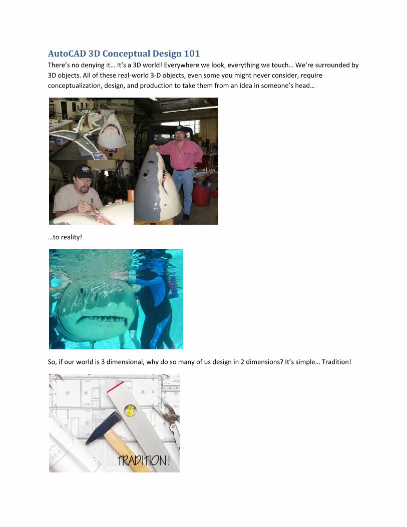
AutoCAD 3D Conceptual Design 101 There’s no denying it… It’s a 3D world! Everywhere we look, everything we touch… We’re surrounded by
3D objects. All of these real‐world 3‐D objects, even some you might never consider, require
conceptualization, design, and production to take them from an idea in someone’s head…
…to reality!
So, if our world is 3 dimensional, why do so many of us design in 2 dimensions? It’s simple… Tradition!
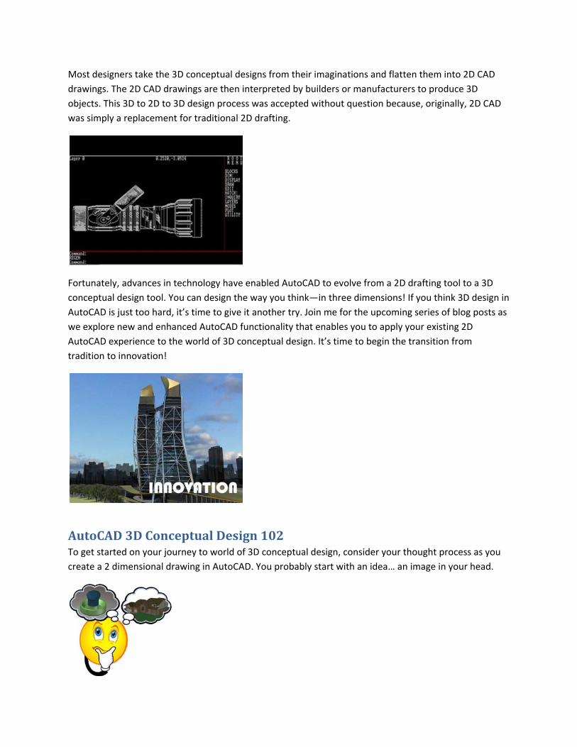
Most designers take the 3D conceptual designs from their imaginations and flatten them into 2D CAD
drawings. The 2D CAD drawings are then interpreted by builders or manufacturers to produce 3D
objects. This 3D to 2D to 3D design process was accepted without question because, originally, 2D CAD
was simply a replacement for traditional 2D drafting.
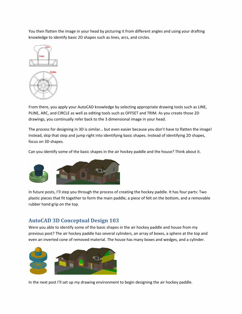
Fortunately, advances in technology have enabled AutoCAD to evolve from a 2D drafting tool to a 3D
conceptual design tool. You can design the way you think—in three dimensions! If you think 3D design in
AutoCAD is just too hard, it’s time to give it another try. Join me for the upcoming series of blog posts as
we explore new and enhanced AutoCAD functionality that enables you to apply your existing 2D
AutoCAD experience to the world of 3D conceptual design. It’s time to begin the transition from
tradition to innovation!
AutoCAD 3D Conceptual Design 102 To get started on your journey to world of 3D conceptual design, consider your thought process as you
create a 2 dimensional drawing in AutoCAD. You probably start with an idea… an image in your head.
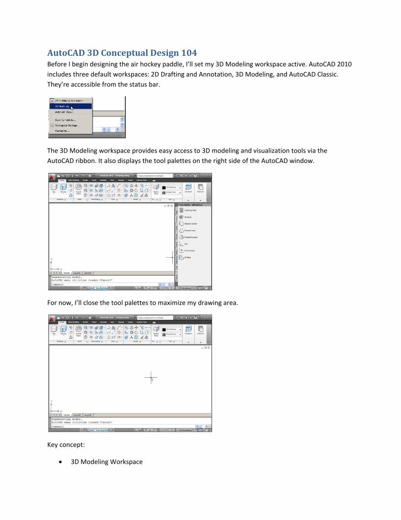
You then flatten the image in your head by picturing it from different angles and using your drafting
knowledge to identify basic 2D shapes such as lines, arcs, and circles.
From there, you apply your AutoCAD knowledge by selecting appropriate drawing tools such as LINE,
PLINE, ARC, and CIRCLE as well as editing tools such as OFFSET and TRIM. As you create those 2D
drawings, you continually refer back to the 3 dimensional image in your head.
The process for designing in 3D is similar… but even easier because you don’t have to flatten the image!
Instead, skip that step and jump right into identifying basic shapes. Instead of identifying 2D shapes,
focus on 3D shapes.
Can you identify some of the basic shapes in the air hockey paddle and the house? Think about it.
In future posts, I’ll step you through the process of creating the hockey paddle. It has four parts: Two
plastic pieces that fit together to form the main paddle, a piece of felt on the bottom, and a removable
rubber hand grip on the top.
AutoCAD 3D Conceptual Design 103 Were you able to identify some of the basic shapes in the air hockey paddle and house from my
previous post? The air hockey paddle has several cylinders, an array of boxes, a sphere at the top and
even an inverted cone of removed material. The house has many boxes and wedges, and a cylinder.
In the next post I’ll set up my drawing environment to begin designing the air hockey paddle.
AutoCAD 3D Conceptual Design 104 Before I begin designing the air hockey paddle, I’ll set my 3D Modeling workspace active. AutoCAD 2010
includes three default workspaces: 2D Drafting and Annotation, 3D Modeling, and AutoCAD Classic.
They’re accessible from the status bar.
The 3D Modeling workspace provides easy access to 3D modeling and visualization tools via the
AutoCAD ribbon. It also displays the tool palettes on the right side of the AutoCAD window.
For now, I’ll close the tool palettes to maximize my drawing area.
Key concept:
3D Modeling Workspace
AutoCAD 3D Conceptual Design 105 Now I’m ready to start designing the air hockey paddle. I’ll begin by drawing a solid cylinder. The solid
cylinder tool is available in the Primitives panel on the Home tab of the 3D Modeling workspace. You’ll
find a flyout with all the solid primitive tools. The box tool is displayed by default but the flyout will
update to display whatever tool you used last. If you’re a keyboarder, you can use the command alias
CYL (CYLINDER command).
Drawing a cylinder feels very much like drawing a circle. Compare the prompts. You can create a circle
based on 3 points, 2 points, or 2 tangents and a radius in addition to the default option which requires
you to specify the center and radius.
You can create a cylinder using the same options (3P, 2P, Ttr). In addition, the cylinder tool includes an
Ellipse option that enables you to create an elliptical cylinder (similar to drawing an ellipse). For now, I’ll
use the simple and familiar default option by specifying a center and radius for the cylinder.
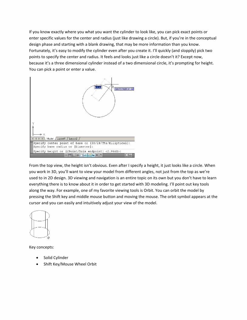
If you know exactly where you what you want the cylinder to look like, you can pick exact points or
enter specific values for the center and radius (just like drawing a circle). But, if you’re in the conceptual
design phase and starting with a blank drawing, that may be more information than you know.
Fortunately, it’s easy to modify the cylinder even after you create it. I’ll quickly (and sloppily) pick two
points to specify the center and radius. It feels and looks just like a circle doesn’t it? Except now,
because it’s a three dimensional cylinder instead of a two dimensional circle, it’s prompting for height.
You can pick a point or enter a value.
From the top view, the height isn’t obvious. Even after I specify a height, it just looks like a circle. When
you work in 3D, you’ll want to view your model from different angles, not just from the top as we’re
used to in 2D design. 3D viewing and navigation is an entire topic on its own but you don’t have to learn
everything there is to know about it in order to get started with 3D modeling. I’ll point out key tools
along the way. For example, one of my favorite viewing tools is Orbit. You can orbit the model by
pressing the Shift key and middle mouse button and moving the mouse. The orbit symbol appears at the
cursor and you can easily and intuitively adjust your view of the model.
Key concepts:
Solid Cylinder
Shift Key/Mouse Wheel Orbit
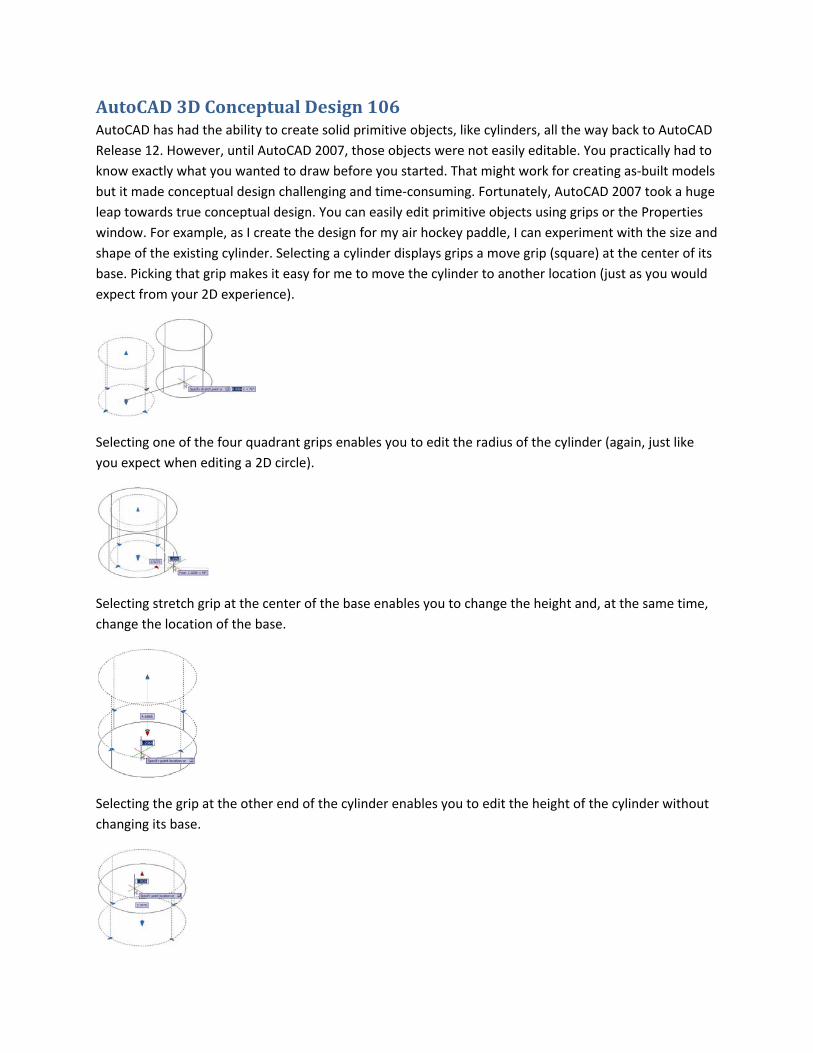
AutoCAD 3D Conceptual Design 106 AutoCAD has had the ability to create solid primitive objects, like cylinders, all the way back to AutoCAD
Release 12. However, until AutoCAD 2007, those objects were not easily editable. You practically had to
know exactly what you wanted to draw before you started. That might work for creating as‐built models
but it made conceptual design challenging and time‐consuming. Fortunately, AutoCAD 2007 took a huge
leap towards true conceptual design. You can easily edit primitive objects using grips or the Properties
window. For example, as I create the design for my air hockey paddle, I can experiment with the size and
shape of the existing cylinder. Selecting a cylinder displays grips a move grip (square) at the center of its
base. Picking that grip makes it easy for me to move the cylinder to another location (just as you would
expect from your 2D experience).
Selecting one of the four quadrant grips enables you to edit the radius of the cylinder (again, just like
you expect when editing a 2D circle).
Selecting stretch grip at the center of the base enables you to change the height and, at the same time,
change the location of the base.
Selecting the grip at the other end of the cylinder enables you to edit the height of the cylinder without
changing its base.
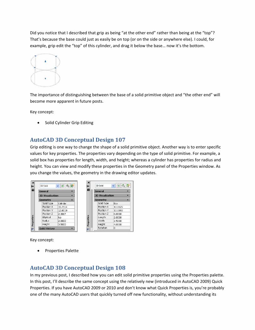
Did you notice that I described that grip as being “at the other end” rather than being at the “top”?
That’s because the base could just as easily be on top (or on the side or anywhere else). I could, for
example, grip edit the “top” of this cylinder, and drag it below the base… now it’s the bottom.
The importance of distinguishing between the base of a solid primitive object and “the other end” will
become more apparent in future posts.
Key concept:
Solid Cylinder Grip Editing
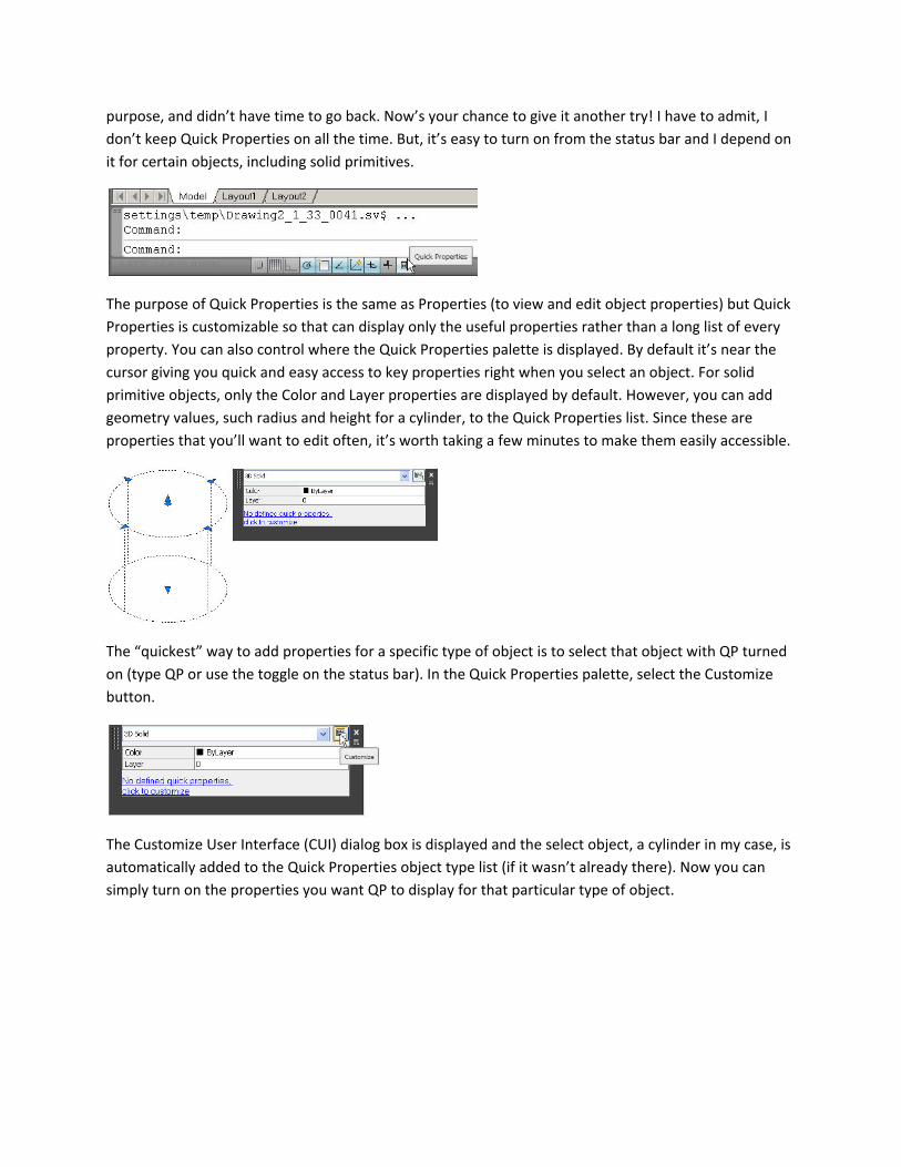
AutoCAD 3D Conceptual Design 107 Grip editing is one way to change the shape of a solid primitive object. Another way is to enter specific
values for key properties. The properties vary depending on the type of solid primitive. For example, a
solid box has properties for length, width, and height; whereas a cylinder has properties for radius and
height. You can view and modify these properties in the Geometry panel of the Properties window. As
you change the values, the geometry in the drawing editor updates.
Key concept:
Properties Palette
AutoCAD 3D Conceptual Design 108 In my previous post, I described how you can edit solid primitive properties using the Properties palette.
In this post, I’ll describe the same concept using the relatively new (introduced in AutoCAD 2009) Quick
Properties. If you have AutoCAD 2009 or 2010 and don’t know what Quick Properties is, you’re probably
one of the many AutoCAD users that quickly turned off new functionality, without understanding its
purpose, and didn’t have time to go back. Now’s your chance to give it another try! I have to admit, I
don’t keep Quick Properties on all the time. But, it’s easy to turn on from the status bar and I depend on
it for certain objects, including solid primitives.
The purpose of Quick Properties is the same as Properties (to view and edit object properties) but Quick
Properties is customizable so that can display only the useful properties rather than a long list of every
property. You can also control where the Quick Properties palette is displayed. By default it’s near the
cursor giving you quick and easy access to key properties right when you select an object. For solid
primitive objects, only the Color and Layer properties are displayed by default. However, you can add
geometry values, such radius and height for a cylinder, to the Quick Properties list. Since these are
properties that you’ll want to edit often, it’s worth taking a few minutes to make them easily accessible.
The “quickest” way to add properties for a specific type of object is to select that object with QP turned
on (type QP or use the toggle on the status bar). In the Quick Properties palette, select the Customize
button.
The Customize User Interface (CUI) dialog box is displayed and the select object, a cylinder in my case, is
automatically added to the Quick Properties object type list (if it wasn’t already there). Now you can
simply turn on the properties you want QP to display for that particular type of object.
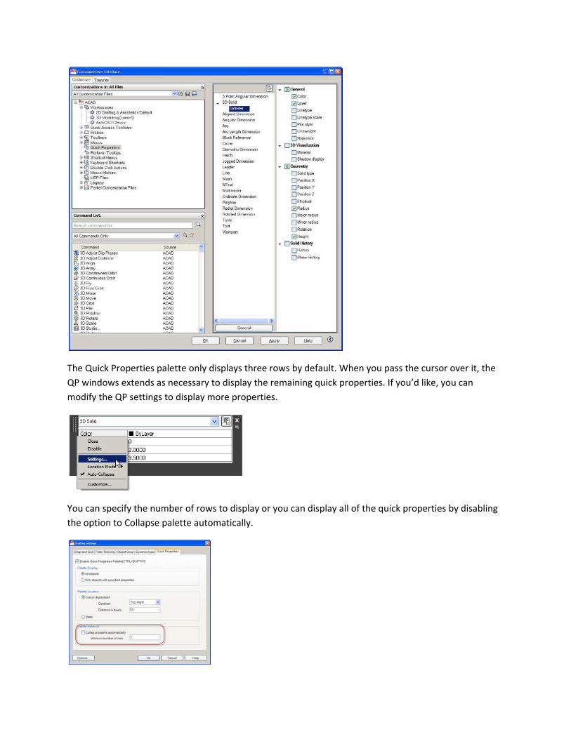
The Quick Properties palette only displays three rows by default. When you pass the cursor over it, the
QP windows extends as necessary to display the remaining quick properties. If you’d like, you can
modify the QP settings to display more properties.
You can specify the number of rows to display or you can display all of the quick properties by disabling
the option to Collapse palette automatically.
Now, when I select a cylinder, I can easily modify the radius and height in the Quick Properties window right
near my cursor! I’ll change the radius and height of the cylinder for my air hockey paddle to 30 and 14.
Key concept:
Quick Properties
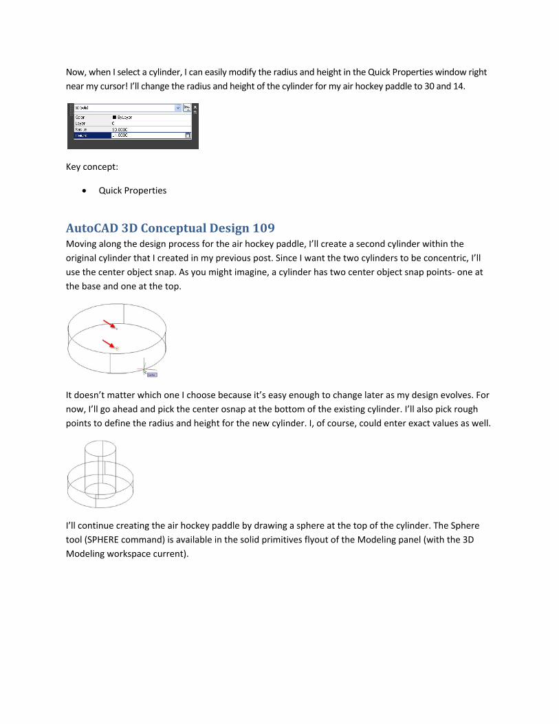
AutoCAD 3D Conceptual Design 109 Moving along the design process for the air hockey paddle, I’ll create a second cylinder within the
original cylinder that I created in my previous post. Since I want the two cylinders to be concentric, I’ll
use the center object snap. As you might imagine, a cylinder has two center object snap points‐ one at
the base and one at the top.
It doesn’t matter which one I choose because it’s easy enough to change later as my design evolves. For
now, I’ll go ahead and pick the center osnap at the bottom of the existing cylinder. I’ll also pick rough
points to define the radius and height for the new cylinder. I, of course, could enter exact values as well.
I’ll continue creating the air hockey paddle by drawing a sphere at the top of the cylinder. The Sphere
tool (SPHERE command) is available in the solid primitives flyout of the Modeling panel (with the 3D
Modeling workspace current).
Drawing a sphere is much like drawing a circle. You can use the default center/radius option or choose
from 3Point, 2Point, and TanTanRadius.
I’ll use the default center/radius option and place it at the center of the top of the cylinder then use the
quadrant osnap to specify the same radius as the cylinder.
Even if you’re completely new to 3D design in AutoCAD, these tools should feel familiar based on your
2D experience.
Key concept:
Sphere Solid
AutoCAD 3D Conceptual Design 110 In previous posts, I created two cylinders and a sphere for the air hockey paddle. Now I’ll create a solid
cone, which I’ll use to remove material from the large cylinder. I could create the cone with the correct
values right from the start. But, since I’m still in the conceptual design phase, I’m going to draw a cone
by snapping to the existing cylinder and then I’ll modify my design.
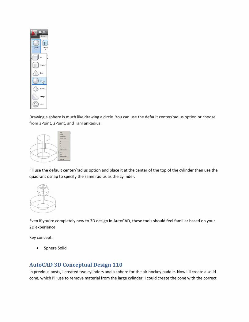
The Cone tool (CONE command) is available in the solid primitives flyout of the Modeling panel (with the
3D Modeling workspace current).
The options for creating a cone are similar to creating a cylinder (and a circle). First, you specify the
location and size of the base of the cone. You can use the default center/radius option or choose from
3Point, 2Point, TanTanRadius, and Elliptical. Just like with drawing a circle in 2D, the option you choose
depends on what you’re trying to create, what existing objects you can snap to, and what you know.
I’ll use the default Center/Radius option and snap to the center and quadrant at the top of original
cylinder. After specifying the base of the cone, the default option is to enter a value or pick a point to
specify the height. However, there are additional options as well. A right‐click menu (and the Command
line) enable you to pick 2 points to determine the height, pick a point to specify the height and change
the orientation at the same time, or enter a value for the top radius.
If you don’t enter a value for the top radius, it assumes a value of zero and creates the cone with a sharp
point. Also, keep in mind that, like a cylinder, the base and top of a cone don’t necessarily mean that the
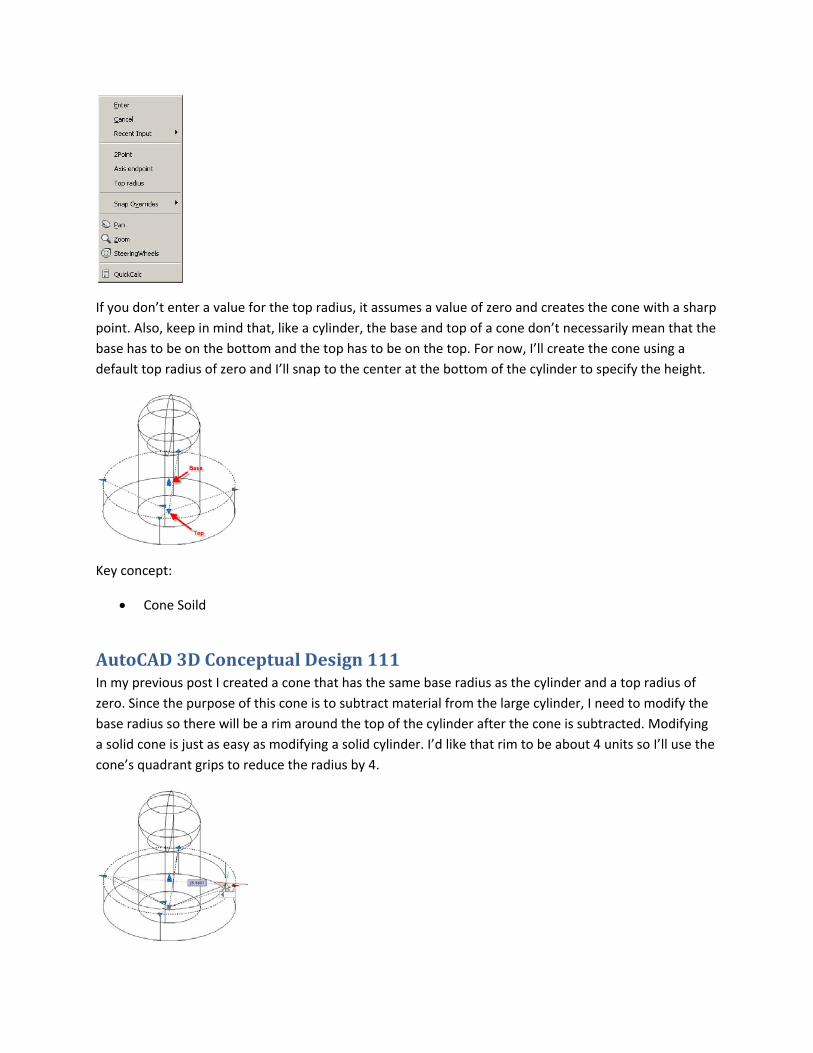
base has to be on the bottom and the top has to be on the top. For now, I’ll create the cone using a
default top radius of zero and I’ll snap to the center at the bottom of the cylinder to specify the height.
Key concept:
Cone Soild
AutoCAD 3D Conceptual Design 111 In my previous post I created a cone that has the same base radius as the cylinder and a top radius of
zero. Since the purpose of this cone is to subtract material from the large cylinder, I need to modify the
base radius so there will be a rim around the top of the cylinder after the cone is subtracted. Modifying
a solid cone is just as easy as modifying a solid cylinder. I’d like that rim to be about 4 units so I’ll use the
cone’s quadrant grips to reduce the radius by 4.
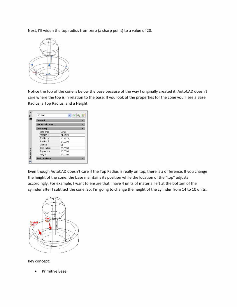
Next, I’ll widen the top radius from zero (a sharp point) to a value of 20.
Notice the top of the cone is below the base because of the way I originally created it. AutoCAD doesn’t
care where the top is in relation to the base. If you look at the properties for the cone you’ll see a Base
Radius, a Top Radius, and a Height.
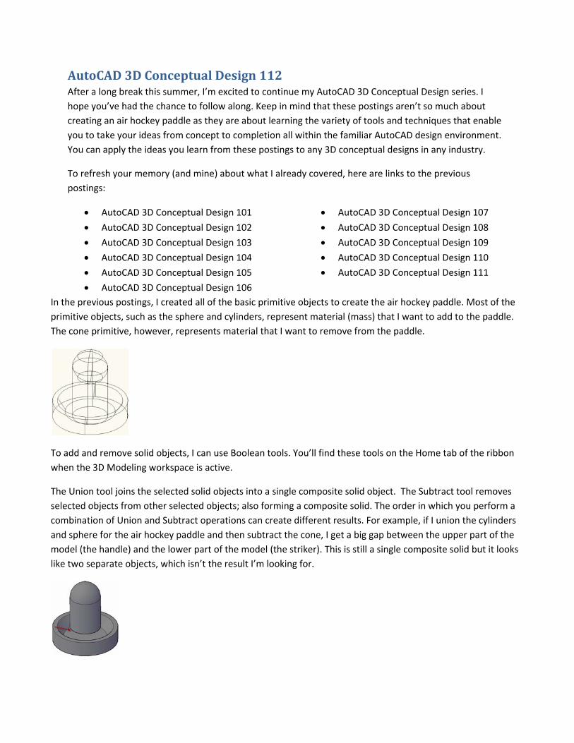
Even though AutoCAD doesn’t care if the Top Radius is really on top, there is a difference. If you change
the height of the cone, the base maintains its position while the location of the “top” adjusts
accordingly. For example, I want to ensure that I have 4 units of material left at the bottom of the
cylinder after I subtract the cone. So, I’m going to change the height of the cylinder from 14 to 10 units.
Key concept:
Primitive Base
AutoCAD 3D Conceptual Design 112 After a long break this summer, I’m excited to continue my AutoCAD 3D Conceptual Design series. I
hope you’ve had the chance to follow along. Keep in mind that these postings aren’t so much about
creating an air hockey paddle as they are about learning the variety of tools and techniques that enable
you to take your ideas from concept to completion all within the familiar AutoCAD design environment.
You can apply the ideas you learn from these postings to any 3D conceptual designs in any industry.
To refresh your memory (and mine) about what I already covered, here are links to the previous
postings:
AutoCAD 3D Conceptual Design 101
AutoCAD 3D Conceptual Design 102
AutoCAD 3D Conceptual Design 103
AutoCAD 3D Conceptual Design 104
AutoCAD 3D Conceptual Design 105
AutoCAD 3D Conceptual Design 106
AutoCAD 3D Conceptual Design 107
AutoCAD 3D Conceptual Design 108
AutoCAD 3D Conceptual Design 109
AutoCAD 3D Conceptual Design 110
AutoCAD 3D Conceptual Design 111
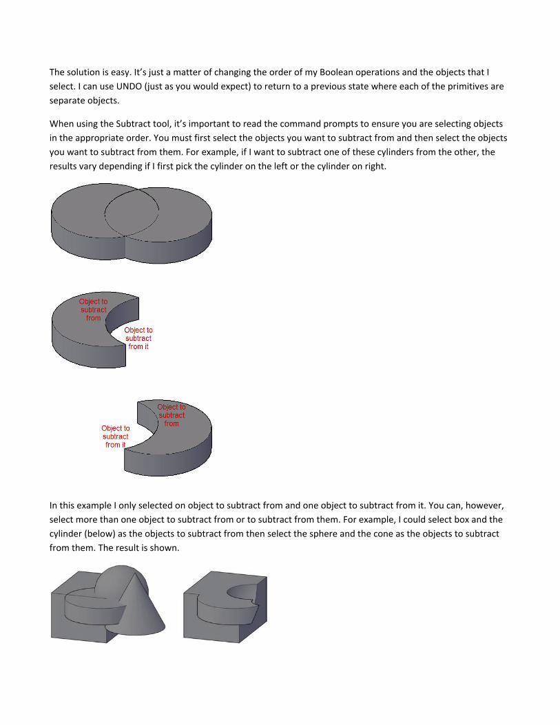
In the previous postings, I created all of the basic primitive objects to create the air hockey paddle. Most of the
primitive objects, such as the sphere and cylinders, represent material (mass) that I want to add to the paddle.
The cone primitive, however, represents material that I want to remove from the paddle.
To add and remove solid objects, I can use Boolean tools. You’ll find these tools on the Home tab of the ribbon
when the 3D Modeling workspace is active.
The Union tool joins the selected solid objects into a single composite solid object. The Subtract tool removes
selected objects from other selected objects; also forming a composite solid. The order in which you perform a
combination of Union and Subtract operations can create different results. For example, if I union the cylinders
and sphere for the air hockey paddle and then subtract the cone, I get a big gap between the upper part of the
model (the handle) and the lower part of the model (the striker). This is still a single composite solid but it looks
like two separate objects, which isn’t the result I’m looking for.
The solution is easy. It’s just a matter of changing the order of my Boolean operations and the objects that I
select. I can use UNDO (just as you would expect) to return to a previous state where each of the primitives are
separate objects.
When using the Subtract tool, it’s important to read the command prompts to ensure you are selecting objects
in the appropriate order. You must first select the objects you want to subtract from and then select the objects
you want to subtract from them. For example, if I want to subtract one of these cylinders from the other, the
results vary depending if I first pick the cylinder on the left or the cylinder on right.
In this example I only selected on object to subtract from and one object to subtract from it. You can, however,
select more than one object to subtract from or to subtract from them. For example, I could select box and the
cylinder (below) as the objects to subtract from then select the sphere and the cone as the objects to subtract
from them. The result is shown.
Since you can select multiple objects, you must remember to press enter to finish the “select from” option
before you select the object(s) you want to subtract from them. This may seem obvious but, speaking from
experience, it’s easy to make a mistake with the selections if you’re new to the Subtract tool or if you haven’t
used it for a while because this is one of the few AutoCAD commands that prompts for two selection sets.
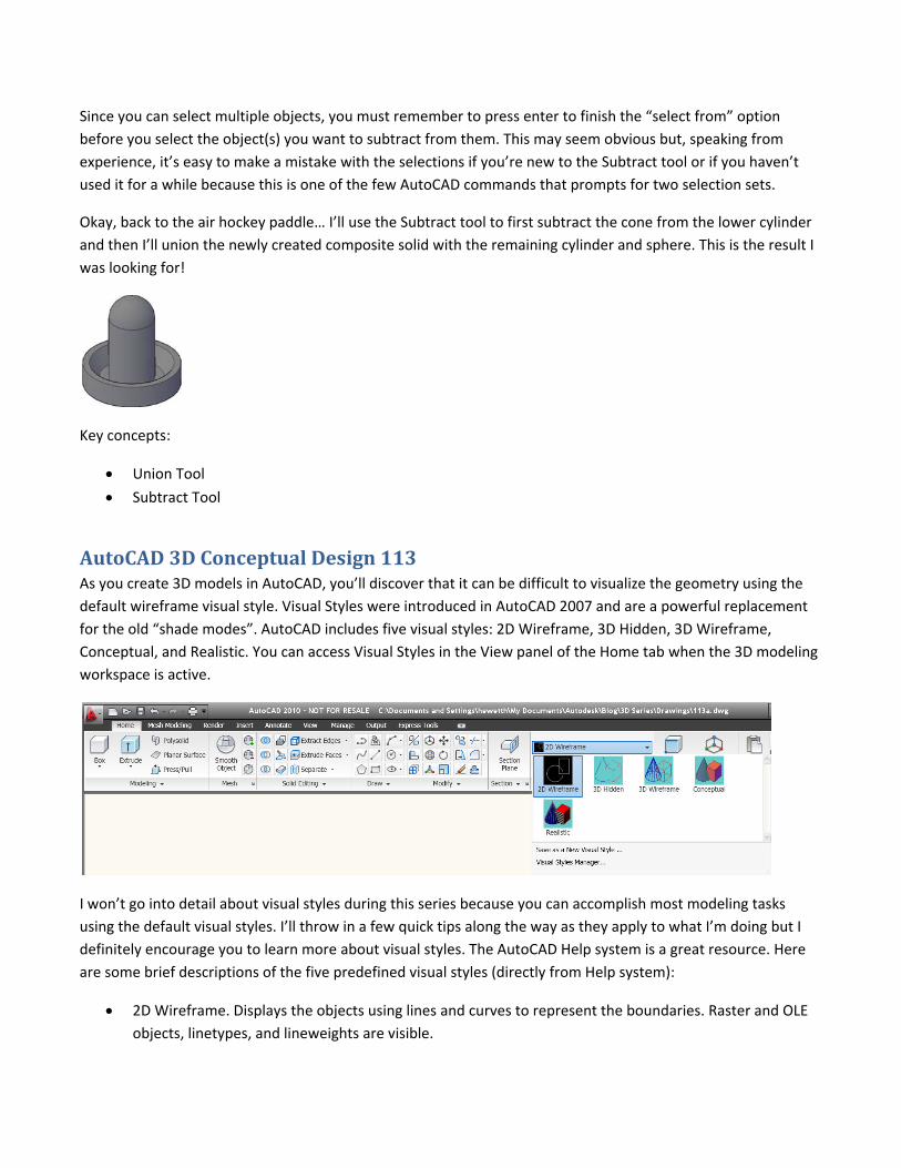
Okay, back to the air hockey paddle… I’ll use the Subtract tool to first subtract the cone from the lower cylinder
and then I’ll union the newly created composite solid with the remaining cylinder and sphere. This is the result I
was looking for!
Key concepts:
Union Tool
Subtract Tool
AutoCAD 3D Conceptual Design 113 As you create 3D models in AutoCAD, you’ll discover that it can be difficult to visualize the geometry using the
default wireframe visual style. Visual Styles were introduced in AutoCAD 2007 and are a powerful replacement
for the old “shade modes”. AutoCAD includes five visual styles: 2D Wireframe, 3D Hidden, 3D Wireframe,
Conceptual, and Realistic. You can access Visual Styles in the View panel of the Home tab when the 3D modeling
workspace is active.
I won’t go into detail about visual styles during this series because you can accomplish most modeling tasks
using the default visual styles. I’ll throw in a few quick tips along the way as they apply to what I’m doing but I
definitely encourage you to learn more about visual styles. The AutoCAD Help system is a great resource. Here
are some brief descriptions of the five predefined visual styles (directly from Help system):
2D Wireframe. Displays the objects using lines and curves to represent the boundaries. Raster and OLE
objects, linetypes, and lineweights are visible.
3D Wireframe (upper left in the illustration). Displays the objects using lines and curves to represent the
boundaries.
3D Hidden (upper right). Displays the objects using 3D wireframe representation and hides lines
representing back faces.
Realistic (lower left). Shades the objects and smooths the edges between polygon faces. Materials that
you have attached to the objects are displayed.
Conceptual (lower right). Shades the objects and smooths the edges between polygon faces. Shading
uses the Gooch face style, a transition between cool and warm colors rather than dark to light. The
effect is less realistic, but it can make the details of the model easier to see.
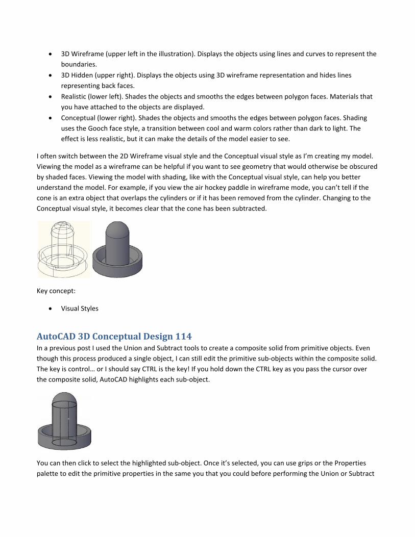
I often switch between the 2D Wireframe visual style and the Conceptual visual style as I’m creating my model.
Viewing the model as a wireframe can be helpful if you want to see geometry that would otherwise be obscured
by shaded faces. Viewing the model with shading, like with the Conceptual visual style, can help you better
understand the model. For example, if you view the air hockey paddle in wireframe mode, you can’t tell if the
cone is an extra object that overlaps the cylinders or if it has been removed from the cylinder. Changing to the
Conceptual visual style, it becomes clear that the cone has been subtracted.
Key concept:
Visual Styles
AutoCAD 3D Conceptual Design 114 In a previous post I used the Union and Subtract tools to create a composite solid from primitive objects. Even
though this process produced a single object, I can still edit the primitive sub‐objects within the composite solid.
The key is control… or I should say CTRL is the key! If you hold down the CTRL key as you pass the cursor over
the composite solid, AutoCAD highlights each sub‐object.
You can then click to select the highlighted sub‐object. Once it’s selected, you can use grips or the Properties
palette to edit the primitive properties in the same you that you could before performing the Union or Subtract
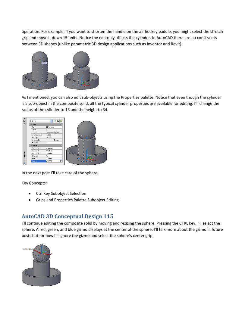
operation. For example, if you want to shorten the handle on the air hockey paddle, you might select the stretch
grip and move it down 15 units. Notice the edit only affects the cylinder. In AutoCAD there are no constraints
between 3D shapes (unlike parametric 3D design applications such as Inventor and Revit).
As I mentioned, you can also edit sub‐objects using the Properties palette. Notice that even though the cylinder
is a sub‐object in the composite solid, all the typical cylinder properties are available for editing. I’ll change the
radius of the cylinder to 13 and the height to 34.
In the next post I’ll take care of the sphere.
Key Concepts:
Ctrl Key Subobject Selection
Grips and Properties Palette Subobject Editing
AutoCAD 3D Conceptual Design 115 I’ll continue editing the composite solid by moving and resizing the sphere. Pressing the CTRL key, I’ll select the
sphere. A red, green, and blue gizmo displays at the center of the sphere. I’ll talk more about the gizmo in future
posts but for now I’ll ignore the gizmo and select the sphere’s center grip.
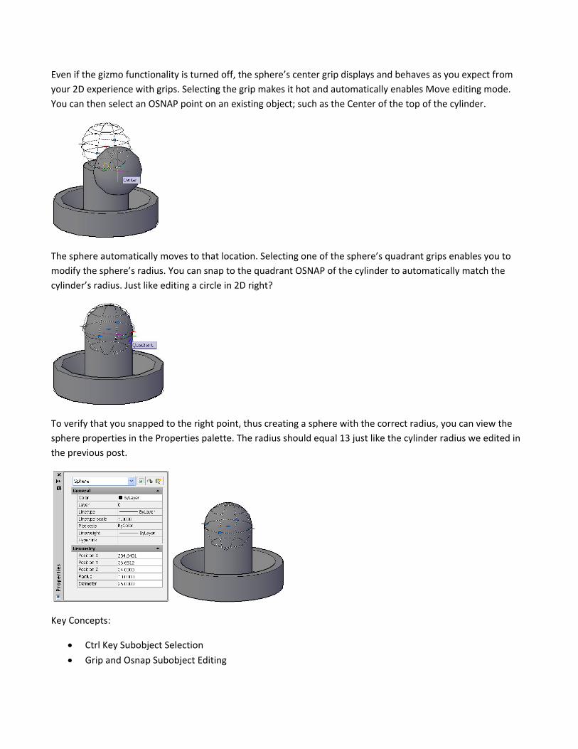
Even if the gizmo functionality is turned off, the sphere’s center grip displays and behaves as you expect from
your 2D experience with grips. Selecting the grip makes it hot and automatically enables Move editing mode.
You can then select an OSNAP point on an existing object; such as the Center of the top of the cylinder.
The sphere automatically moves to that location. Selecting one of the sphere’s quadrant grips enables you to
modify the sphere’s radius. You can snap to the quadrant OSNAP of the cylinder to automatically match the
cylinder’s radius. Just like editing a circle in 2D right?
To verify that you snapped to the right point, thus creating a sphere with the correct radius, you can view the
sphere properties in the Properties palette. The radius should equal 13 just like the cylinder radius we edited in
the previous post.
Key Concepts:
Ctrl Key Subobject Selection
Grip and Osnap Subobject Editing
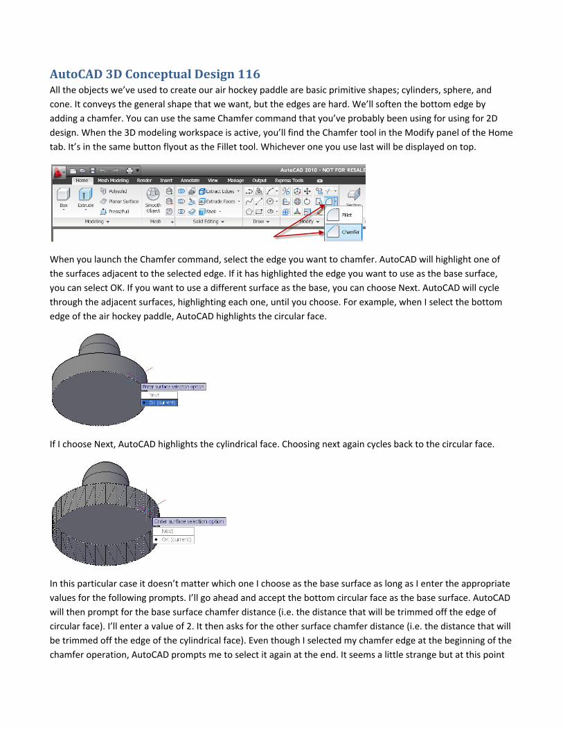
AutoCAD 3D Conceptual Design 116 All the objects we’ve used to create our air hockey paddle are basic primitive shapes; cylinders, sphere, and
cone. It conveys the general shape that we want, but the edges are hard. We’ll soften the bottom edge by
adding a chamfer. You can use the same Chamfer command that you’ve probably been using for using for 2D
design. When the 3D modeling workspace is active, you’ll find the Chamfer tool in the Modify panel of the Home
tab. It’s in the same button flyout as the Fillet tool. Whichever one you use last will be displayed on top.
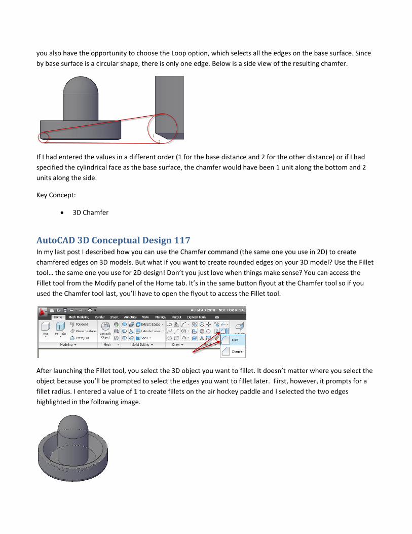
When you launch the Chamfer command, select the edge you want to chamfer. AutoCAD will highlight one of
the surfaces adjacent to the selected edge. If it has highlighted the edge you want to use as the base surface,
you can select OK. If you want to use a different surface as the base, you can choose Next. AutoCAD will cycle
through the adjacent surfaces, highlighting each one, until you choose. For example, when I select the bottom
edge of the air hockey paddle, AutoCAD highlights the circular face.
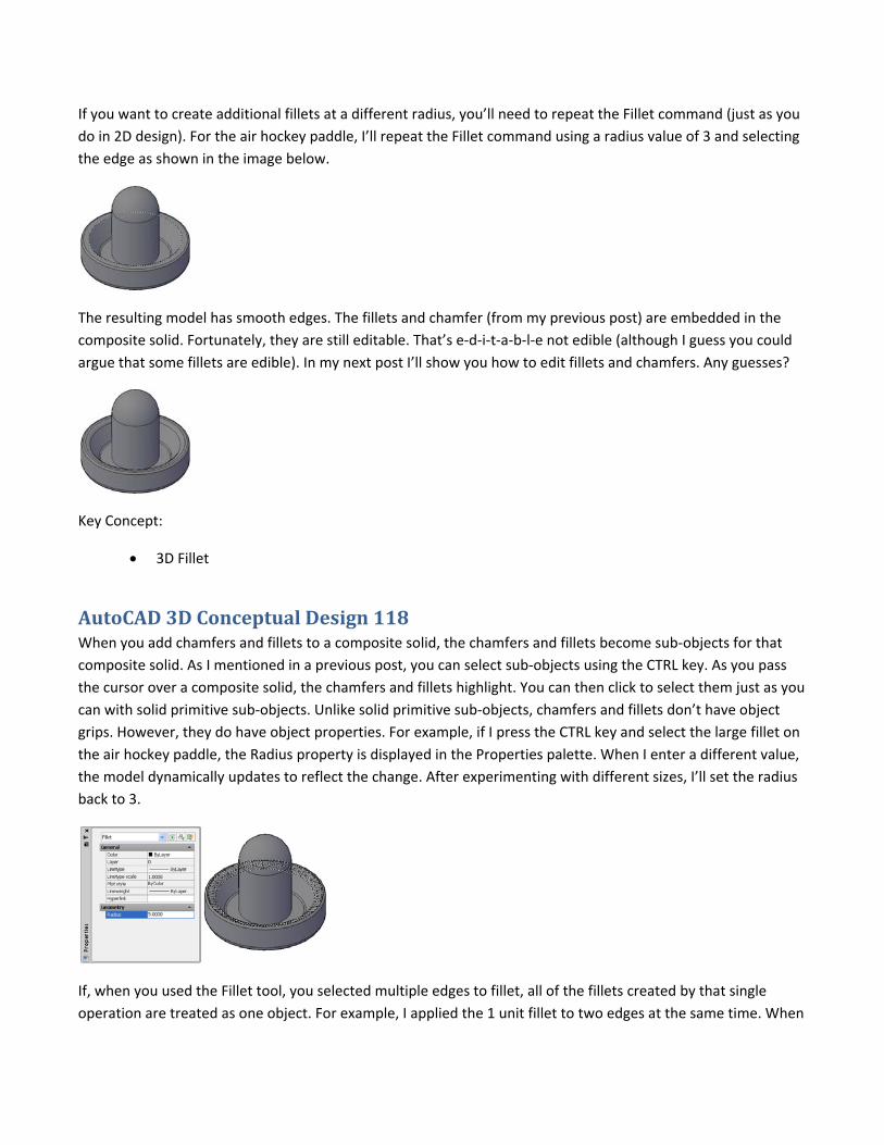
If I choose Next, AutoCAD highlights the cylindrical face. Choosing next again cycles back to the circular face.
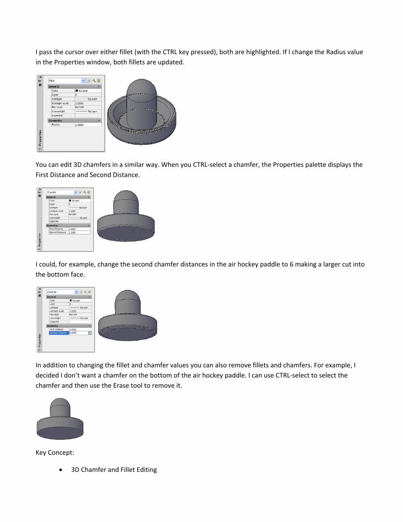
In this particular case it doesn’t matter which one I choose as the base surface as long as I enter the appropriate
values for the following prompts. I’ll go ahead and accept the bottom circular face as the base surface. AutoCAD
will then prompt for the base surface chamfer distance (i.e. the distance that will be trimmed off the edge of
circular face). I’ll enter a value of 2. It then asks for the other surface chamfer distance (i.e. the distance that will
be trimmed off the edge of the cylindrical face). Even though I selected my chamfer edge at the beginning of the
chamfer operation, AutoCAD prompts me to select it again at the end. It seems a little strange but at this point
you also have the opportunity to choose the Loop option, which selects all the edges on the base surface. Since
by base surface is a circular shape, there is only one edge. Below is a side view of the resulting chamfer.
If I had entered the values in a different order (1 for the base distance and 2 for the other distance) or if I had
specified the cylindrical face as the base surface, the chamfer would have been 1 unit along the bottom and 2
units along the side.
Key Concept:
3D Chamfer
AutoCAD 3D Conceptual Design 117 In my last post I described how you can use the Chamfer command (the same one you use in 2D) to create
chamfered edges on 3D models. But what if you want to create rounded edges on your 3D model? Use the Fillet
tool… the same one you use for 2D design! Don’t you just love when things make sense? You can access the
Fillet tool from the Modify panel of the Home tab. It’s in the same button flyout at the Chamfer tool so if you
used the Chamfer tool last, you’ll have to open the flyout to access the Fillet tool.
After launching the Fillet tool, you select the 3D object you want to fillet. It doesn’t matter where you select the
object because you’ll be prompted to select the edges you want to fillet later. First, however, it prompts for a
fillet radius. I entered a value of 1 to create fillets on the air hockey paddle and I selected the two edges
highlighted in the following image.
If you want to create additional fillets at a different radius, you’ll need to repeat the Fillet command (just as you
do in 2D design). For the air hockey paddle, I’ll repeat the Fillet command using a radius value of 3 and selecting
the edge as shown in the image below.
The resulting model has smooth edges. The fillets and chamfer (from my previous post) are embedded in the
composite solid. Fortunately, they are still editable. That’s e‐d‐i‐t‐a‐b‐l‐e not edible (although I guess you could
argue that some fillets are edible). In my next post I’ll show you how to edit fillets and chamfers. Any guesses?
Key Concept:
3D Fillet
AutoCAD 3D Conceptual Design 118 When you add chamfers and fillets to a composite solid, the chamfers and fillets become sub‐objects for that
composite solid. As I mentioned in a previous post, you can select sub‐objects using the CTRL key. As you pass
the cursor over a composite solid, the chamfers and fillets highlight. You can then click to select them just as you
can with solid primitive sub‐objects. Unlike solid primitive sub‐objects, chamfers and fillets don’t have object
grips. However, they do have object properties. For example, if I press the CTRL key and select the large fillet on
the air hockey paddle, the Radius property is displayed in the Properties palette. When I enter a different value,
the model dynamically updates to reflect the change. After experimenting with different sizes, I’ll set the radius
back to 3.
If, when you used the Fillet tool, you selected multiple edges to fillet, all of the fillets created by that single
operation are treated as one object. For example, I applied the 1 unit fillet to two edges at the same time. When
I pass the cursor over either fillet (with the CTRL key pressed), both are highlighted. If I change the Radius value
in the Properties window, both fillets are updated.
You can edit 3D chamfers in a similar way. When you CTRL‐select a chamfer, the Properties palette displays the
First Distance and Second Distance.
I could, for example, change the second chamfer distances in the air hockey paddle to 6 making a larger cut into
the bottom face.
In addition to changing the fillet and chamfer values you can also remove fillets and chamfers. For example, I
decided I don’t want a chamfer on the bottom of the air hockey paddle. I can use CTRL‐select to select the
chamfer and then use the Erase tool to remove it.
Key Concept:
3D Chamfer and Fillet Editing
AutoCAD 3D Conceptual Design 119 All the tools we’ve used to design the air hockey paddle so far have enabled AutoCAD to maintain the integrity
of the sub‐objects. Even after we combined the cylinders, sphere, and cone into a composite solid using Boolean
operations (union and subtract) we could still access and edit the primitive properties by pressing the CTRL key.
We could continue to modify those properties (in addition to the chamfer and fillet properties) even after we
added chamfers and fillets to the model. There are some tools, however, that cause the model to lose that
editing capability. You can save a lot of editing time if you avoid those tools until later in the design process. For
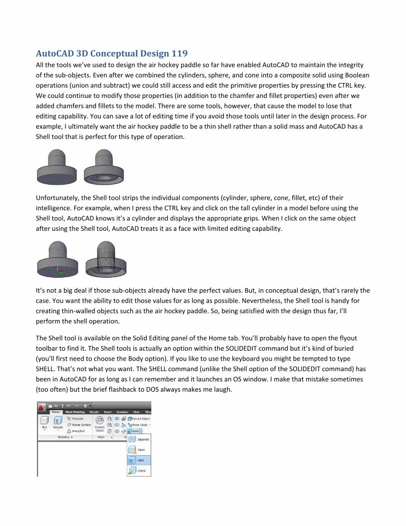
example, I ultimately want the air hockey paddle to be a thin shell rather than a solid mass and AutoCAD has a
Shell tool that is perfect for this type of operation.
Unfortunately, the Shell tool strips the individual components (cylinder, sphere, cone, fillet, etc) of their
intelligence. For example, when I press the CTRL key and click on the tall cylinder in a model before using the
Shell tool, AutoCAD knows it’s a cylinder and displays the appropriate grips. When I click on the same object
after using the Shell tool, AutoCAD treats it as a face with limited editing capability.
It’s not a big deal if those sub‐objects already have the perfect values. But, in conceptual design, that’s rarely the
case. You want the ability to edit those values for as long as possible. Nevertheless, the Shell tool is handy for
creating thin‐walled objects such as the air hockey paddle. So, being satisfied with the design thus far, I’ll
perform the shell operation.
The Shell tool is available on the Solid Editing panel of the Home tab. You’ll probably have to open the flyout
toolbar to find it. The Shell tools is actually an option within the SOLIDEDIT command but it’s kind of buried
(you’ll first need to choose the Body option). If you like to use the keyboard you might be tempted to type
SHELL. That’s not what you want. The SHELL command (unlike the Shell option of the SOLIDEDIT command) has
been in AutoCAD for as long as I can remember and it launches an OS window. I make that mistake sometimes
(too often) but the brief flashback to DOS always makes me laugh.
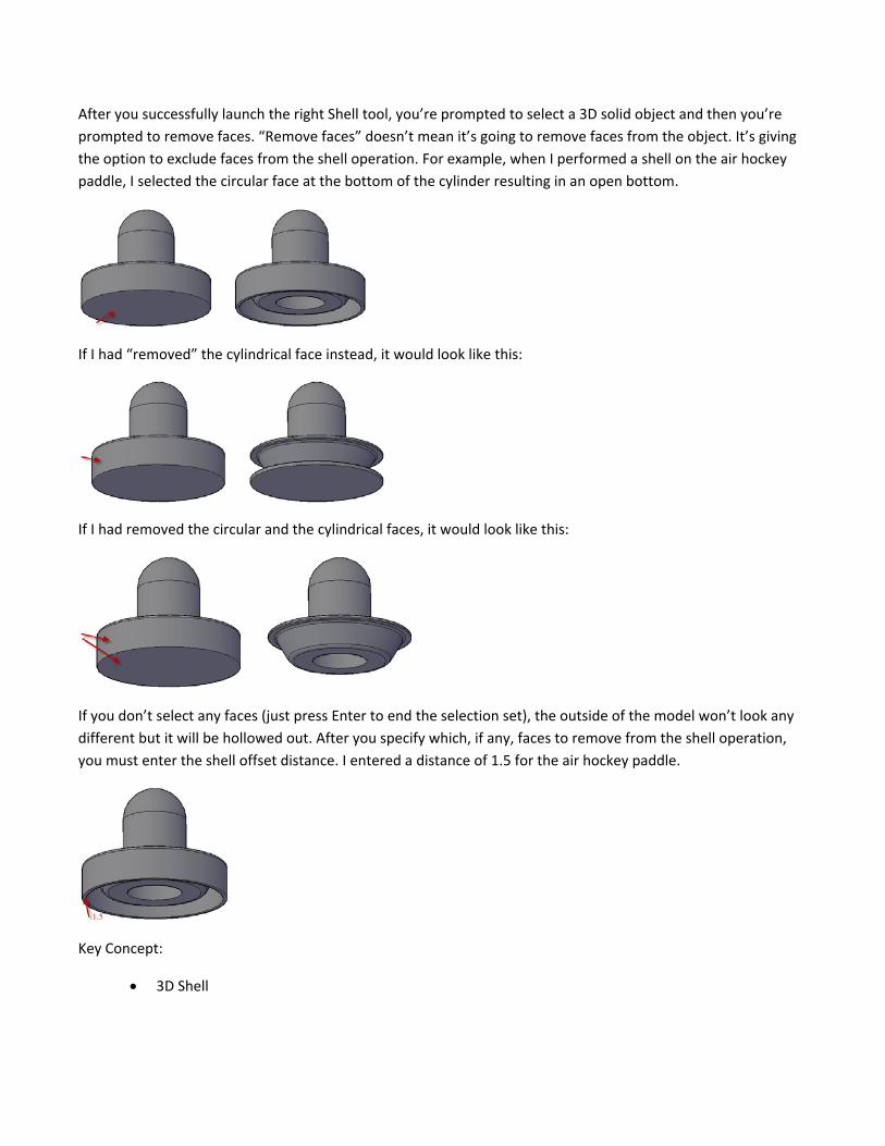
After you successfully launch the right Shell tool, you’re prompted to select a 3D solid object and then you’re
prompted to remove faces. “Remove faces” doesn’t mean it’s going to remove faces from the object. It’s giving
the option to exclude faces from the shell operation. For example, when I performed a shell on the air hockey
paddle, I selected the circular face at the bottom of the cylinder resulting in an open bottom.
If I had “removed” the cylindrical face instead, it would look like this:
If I had removed the circular and the cylindrical faces, it would look like this:
If you don’t select any faces (just press Enter to end the selection set), the outside of the model won’t look any
different but it will be hollowed out. After you specify which, if any, faces to remove from the shell operation,
you must enter the shell offset distance. I entered a distance of 1.5 for the air hockey paddle.
Key Concept:
3D Shell
AutoCAD 3D Conceptual Design 120 In a previous post, I introduced you to two pre‐defined visual styles: 2D Wireframe and Conceptual. These two
visual styles meet most of my needs for visualizing my model during the design process. The wireframe style
enables me to see all of the geometry without it being obscured and the conceptual visual style enables me to
visualize my design without being confused by all the edges that should not, in reality, be visible from a
particular viewpoint. There are times, however, that it can be helpful to view the model with the edges
somewhat obscured. For those times you can use the conceptual visual style with an X‐ray effect. The X‐ray
effect is accessible in the Visual Styles panel of the Render tab.
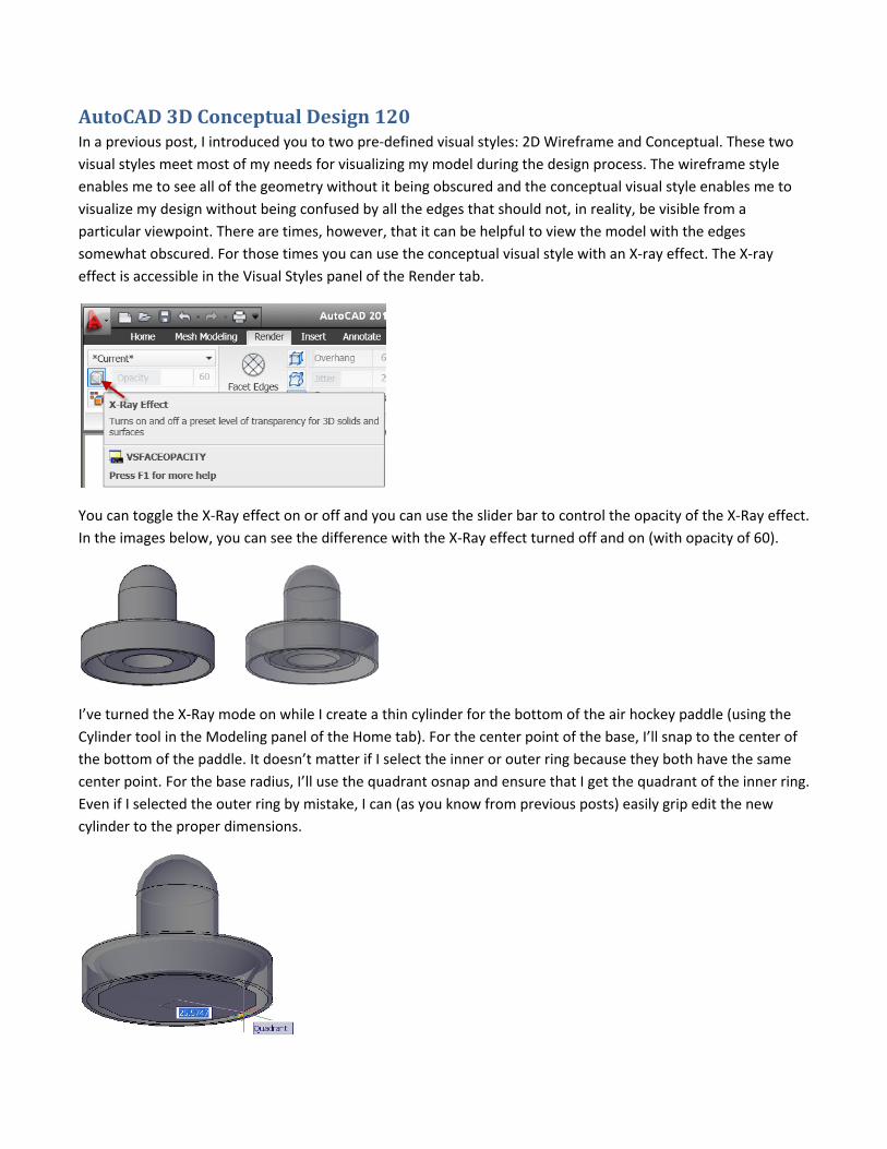
You can toggle the X‐Ray effect on or off and you can use the slider bar to control the opacity of the X‐Ray effect.
In the images below, you can see the difference with the X‐Ray effect turned off and on (with opacity of 60).
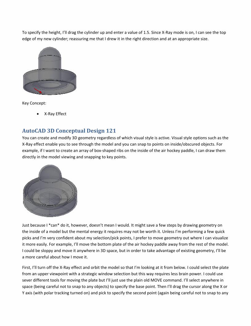
I’ve turned the X‐Ray mode on while I create a thin cylinder for the bottom of the air hockey paddle (using the
Cylinder tool in the Modeling panel of the Home tab). For the center point of the base, I’ll snap to the center of
the bottom of the paddle. It doesn’t matter if I select the inner or outer ring because they both have the same
center point. For the base radius, I’ll use the quadrant osnap and ensure that I get the quadrant of the inner ring.
Even if I selected the outer ring by mistake, I can (as you know from previous posts) easily grip edit the new
cylinder to the proper dimensions.
To specify the height, I’ll drag the cylinder up and enter a value of 1.5. Since X‐Ray mode is on, I can see the top
edge of my new cylinder; reassuring me that I drew it in the right direction and at an appropriate size.
Key Concept:
X‐Ray Effect
AutoCAD 3D Conceptual Design 121 You can create and modify 3D geometry regardless of which visual style is active. Visual style options such as the
X‐Ray effect enable you to see through the model and you can snap to points on inside/obscured objects. For
example, if I want to create an array of box‐shaped ribs on the inside of the air hockey paddle, I can draw them
directly in the model viewing and snapping to key points.
Just because I *can* do it, however, doesn’t mean I would. It might save a few steps by drawing geometry on
the inside of a model but the mental energy it requires may not be worth it. Unless I’m performing a few quick
picks and I’m very confident about my selection/pick points, I prefer to move geometry out where I can visualize
it more easily. For example, I’ll move the bottom plate of the air hockey paddle away from the rest of the model.
I could be sloppy and move it anywhere in 3D space, but in order to take advantage of existing geometry, I’ll be
a more careful about how I move it.
First, I’ll turn off the X‐Ray effect and orbit the model so that I’m looking at it from below. I could select the plate
from an upper viewpoint with a strategic window selection but this way requires less brain power. I could use
sever different tools for moving the plate but I’ll just use the plain old MOVE command. I’ll select anywhere in
space (being careful not to snap to any objects) to specify the base point. Then I’ll drag the cursor along the X or
Y axis (with polar tracking turned on) and pick to specify the second point (again being careful not to snap to any
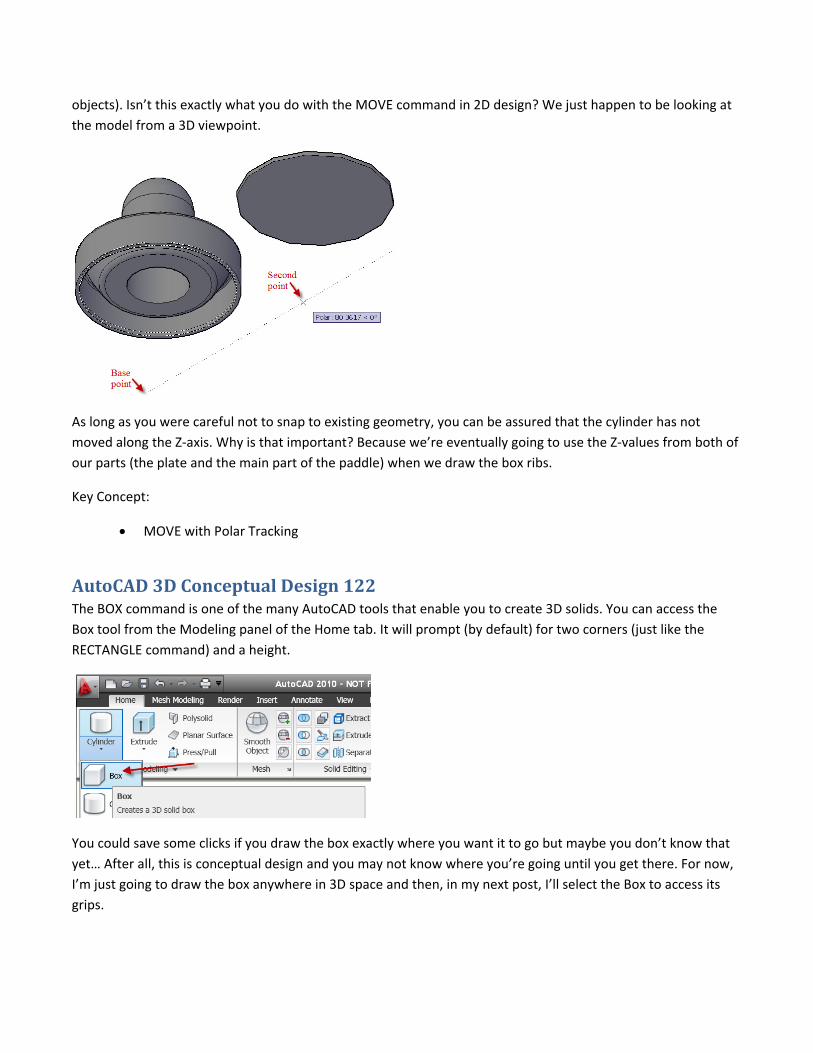
objects). Isn’t this exactly what you do with the MOVE command in 2D design? We just happen to be looking at
the model from a 3D viewpoint.
As long as you were careful not to snap to existing geometry, you can be assured that the cylinder has not
moved along the Z‐axis. Why is that important? Because we’re eventually going to use the Z‐values from both of
our parts (the plate and the main part of the paddle) when we draw the box ribs.
Key Concept:
MOVE with Polar Tracking
AutoCAD 3D Conceptual Design 122 The BOX command is one of the many AutoCAD tools that enable you to create 3D solids. You can access the
Box tool from the Modeling panel of the Home tab. It will prompt (by default) for two corners (just like the
RECTANGLE command) and a height.
You could save some clicks if you draw the box exactly where you want it to go but maybe you don’t know that
yet… After all, this is conceptual design and you may not know where you’re going until you get there. For now,
I’m just going to draw the box anywhere in 3D space and then, in my next post, I’ll select the Box to access its
grips.
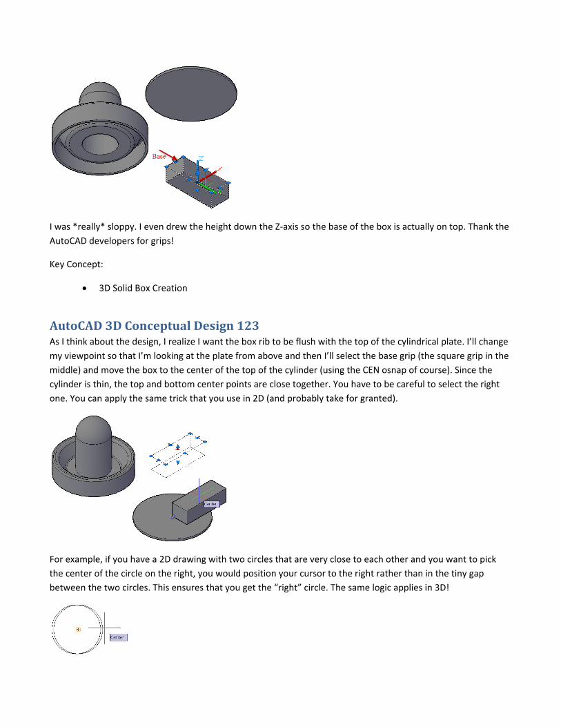
I was *really* sloppy. I even drew the height down the Z‐axis so the base of the box is actually on top. Thank the
AutoCAD developers for grips!
Key Concept:
3D Solid Box Creation
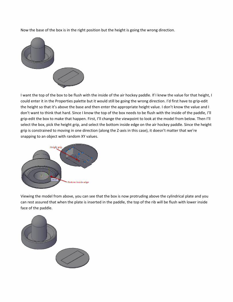
AutoCAD 3D Conceptual Design 123 As I think about the design, I realize I want the box rib to be flush with the top of the cylindrical plate. I’ll change
my viewpoint so that I’m looking at the plate from above and then I’ll select the base grip (the square grip in the
middle) and move the box to the center of the top of the cylinder (using the CEN osnap of course). Since the
cylinder is thin, the top and bottom center points are close together. You have to be careful to select the right
one. You can apply the same trick that you use in 2D (and probably take for granted).
For example, if you have a 2D drawing with two circles that are very close to each other and you want to pick
the center of the circle on the right, you would position your cursor to the right rather than in the tiny gap
between the two circles. This ensures that you get the “right” circle. The same logic applies in 3D!
Now the base of the box is in the right position but the height is going the wrong direction.
I want the top of the box to be flush with the inside of the air hockey paddle. If I knew the value for that height, I
could enter it in the Properties palette but it would still be going the wrong direction. I’d first have to grip‐edit
the height so that it’s above the base and then enter the appropriate height value. I don’t know the value and I
don’t want to think that hard. Since I know the top of the box needs to be flush with the inside of the paddle, I’ll
grip‐edit the box to make that happen. First, I’ll change the viewpoint to look at the model from below. Then I’ll
select the box, pick the height grip, and select the bottom inside edge on the air hockey paddle. Since the height
grip is constrained to moving in one direction (along the Z‐axis in this case), it doesn’t matter that we’re
snapping to an object with random XY values.
Viewing the model from above, you can see that the box is now protruding above the cylindrical plate and you
can rest assured that when the plate is inserted in the paddle, the top of the rib will be flush with lower inside
face of the paddle.
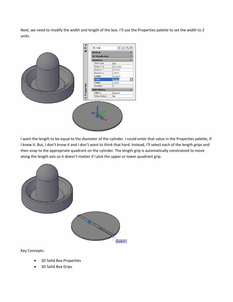
Next, we need to modify the width and length of the box. I’ll use the Properties palette to set the width to 2
units.
I want the length to be equal to the diameter of the cylinder. I could enter that value in the Properties palette, if
I knew it. But, I don’t know it and I don’t want to think that hard. Instead, I’ll select each of the length grips and
then snap to the appropriate quadrant on the cylinder. The length grip is automatically constrained to move
along the length axis so it doesn’t matter if I pick the upper or lower quadrant grip.
Key Concepts:
3D Solid Box Properties
3D Solid Box Grips
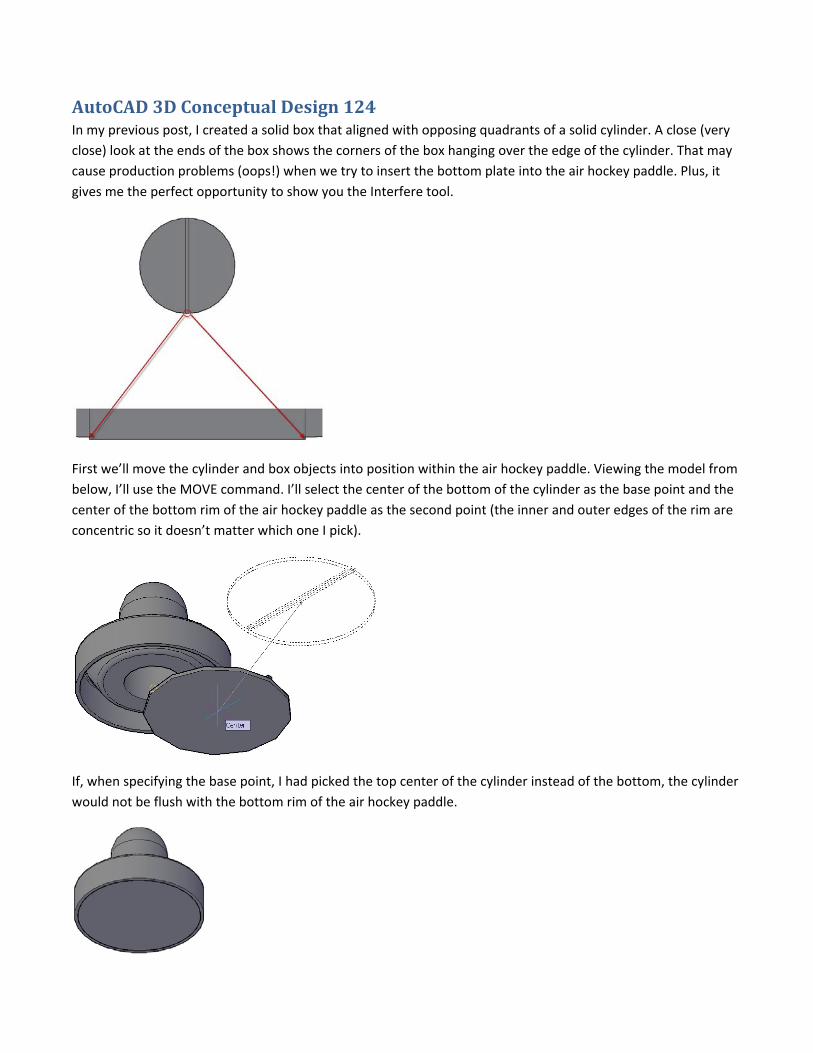
AutoCAD 3D Conceptual Design 124 In my previous post, I created a solid box that aligned with opposing quadrants of a solid cylinder. A close (very
close) look at the ends of the box shows the corners of the box hanging over the edge of the cylinder. That may
cause production problems (oops!) when we try to insert the bottom plate into the air hockey paddle. Plus, it
gives me the perfect opportunity to show you the Interfere tool.
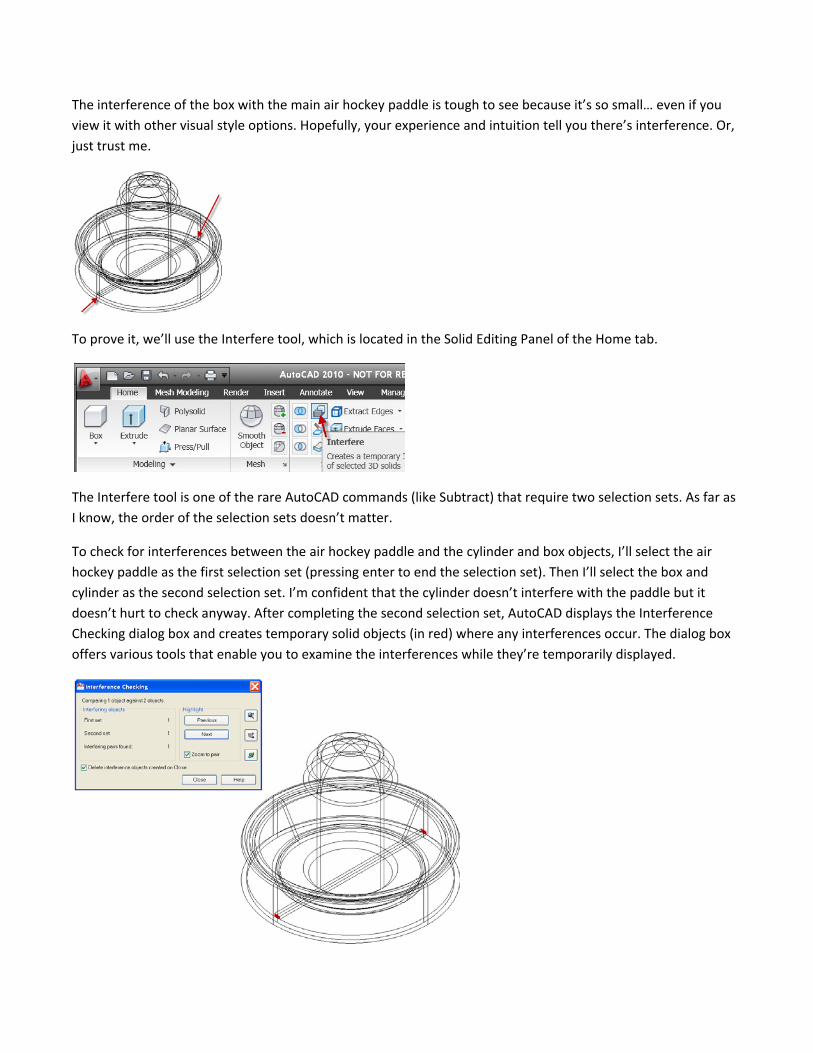
First we’ll move the cylinder and box objects into position within the air hockey paddle. Viewing the model from
below, I’ll use the MOVE command. I’ll select the center of the bottom of the cylinder as the base point and the
center of the bottom rim of the air hockey paddle as the second point (the inner and outer edges of the rim are
concentric so it doesn’t matter which one I pick).
If, when specifying the base point, I had picked the top center of the cylinder instead of the bottom, the cylinder
would not be flush with the bottom rim of the air hockey paddle.
The interference of the box with the main air hockey paddle is tough to see because it’s so small… even if you
view it with other visual style options. Hopefully, your experience and intuition tell you there’s interference. Or,
just trust me.
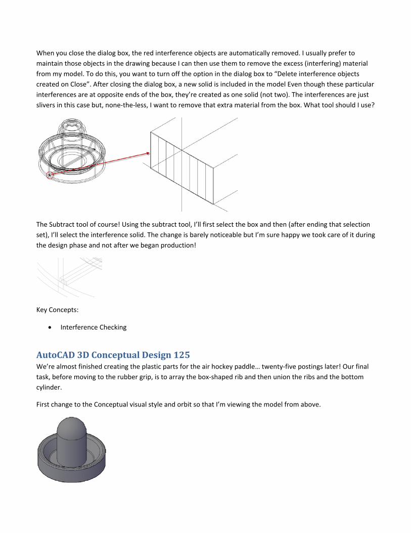
To prove it, we’ll use the Interfere tool, which is located in the Solid Editing Panel of the Home tab.
The Interfere tool is one of the rare AutoCAD commands (like Subtract) that require two selection sets. As far as
I know, the order of the selection sets doesn’t matter.
To check for interferences between the air hockey paddle and the cylinder and box objects, I’ll select the air
hockey paddle as the first selection set (pressing enter to end the selection set). Then I’ll select the box and
cylinder as the second selection set. I’m confident that the cylinder doesn’t interfere with the paddle but it
doesn’t hurt to check anyway. After completing the second selection set, AutoCAD displays the Interference
Checking dialog box and creates temporary solid objects (in red) where any interferences occur. The dialog box
offers various tools that enable you to examine the interferences while they’re temporarily displayed.
When you close the dialog box, the red interference objects are automatically removed. I usually prefer to
maintain those objects in the drawing because I can then use them to remove the excess (interfering) material
from my model. To do this, you want to turn off the option in the dialog box to “Delete interference objects
created on Close”. After closing the dialog box, a new solid is included in the model Even though these particular
interferences are at opposite ends of the box, they’re created as one solid (not two). The interferences are just
slivers in this case but, none‐the‐less, I want to remove that extra material from the box. What tool should I use?
The Subtract tool of course! Using the subtract tool, I’ll first select the box and then (after ending that selection
set), I’ll select the interference solid. The change is barely noticeable but I’m sure happy we took care of it during
the design phase and not after we began production!
Key Concepts:
Interference Checking
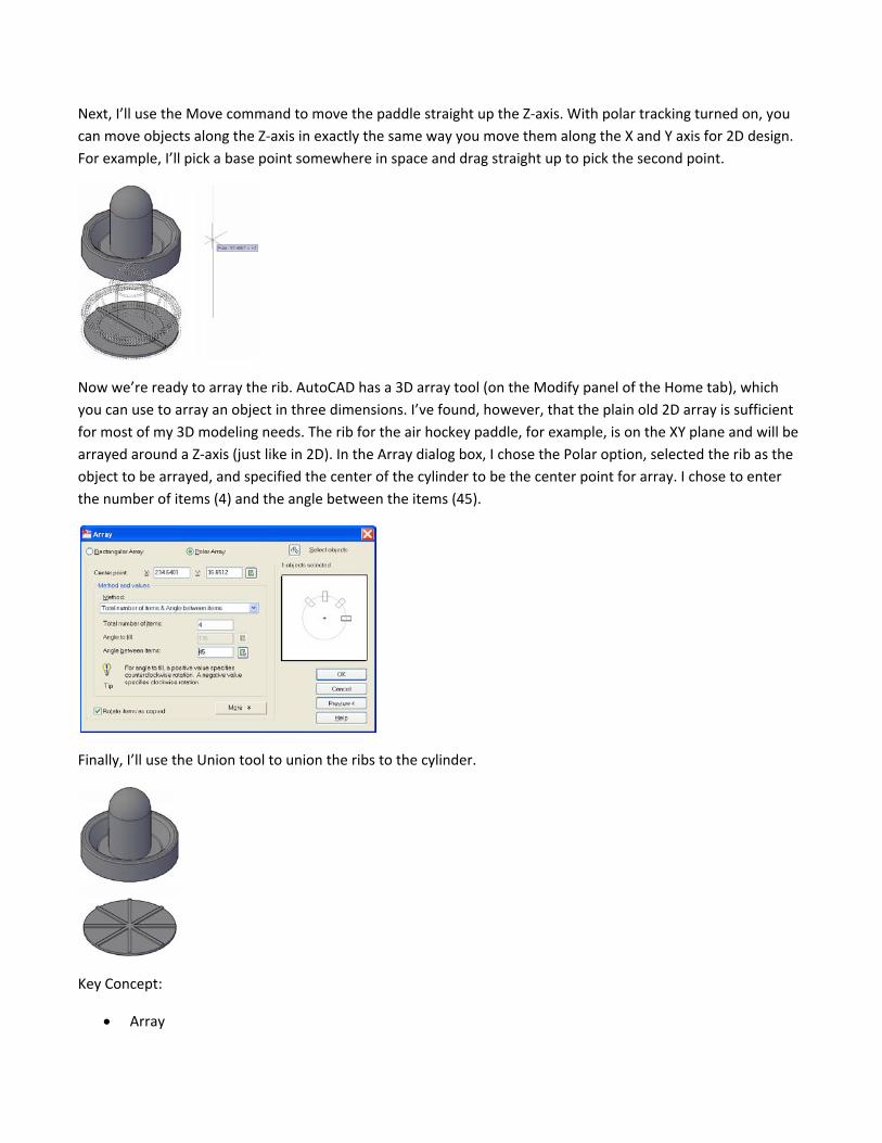
AutoCAD 3D Conceptual Design 125 We’re almost finished creating the plastic parts for the air hockey paddle… twenty‐five postings later! Our final
task, before moving to the rubber grip, is to array the box‐shaped rib and then union the ribs and the bottom
cylinder.
First change to the Conceptual visual style and orbit so that I’m viewing the model from above.
Next, I’ll use the Move command to move the paddle straight up the Z‐axis. With polar tracking turned on, you
can move objects along the Z‐axis in exactly the same way you move them along the X and Y axis for 2D design.
For example, I’ll pick a base point somewhere in space and drag straight up to pick the second point.
Now we’re ready to array the rib. AutoCAD has a 3D array tool (on the Modify panel of the Home tab), which
you can use to array an object in three dimensions. I’ve found, however, that the plain old 2D array is sufficient
for most of my 3D modeling needs. The rib for the air hockey paddle, for example, is on the XY plane and will be
arrayed around a Z‐axis (just like in 2D). In the Array dialog box, I chose the Polar option, selected the rib as the
object to be arrayed, and specified the center of the cylinder to be the center point for array. I chose to enter
the number of items (4) and the angle between the items (45).
Finally, I’ll use the Union tool to union the ribs to the cylinder.
Key Concept:
Array
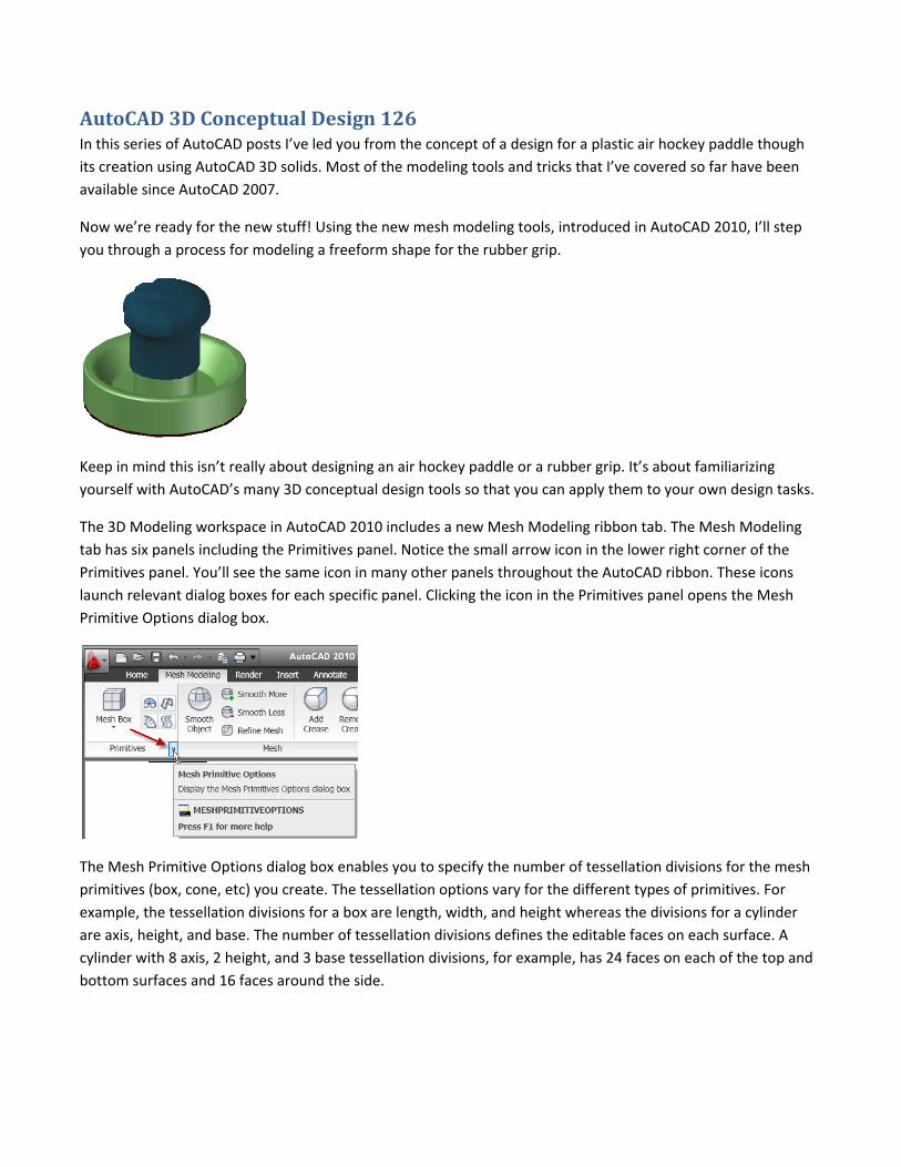
AutoCAD 3D Conceptual Design 126 In this series of AutoCAD posts I’ve led you from the concept of a design for a plastic air hockey paddle though
its creation using AutoCAD 3D solids. Most of the modeling tools and tricks that I’ve covered so far have been
available since AutoCAD 2007.
Now we’re ready for the new stuff! Using the new mesh modeling tools, introduced in AutoCAD 2010, I’ll step
you through a process for modeling a freeform shape for the rubber grip.
Keep in mind this isn’t really about designing an air hockey paddle or a rubber grip. It’s about familiarizing
yourself with AutoCAD’s many 3D conceptual design tools so that you can apply them to your own design tasks.
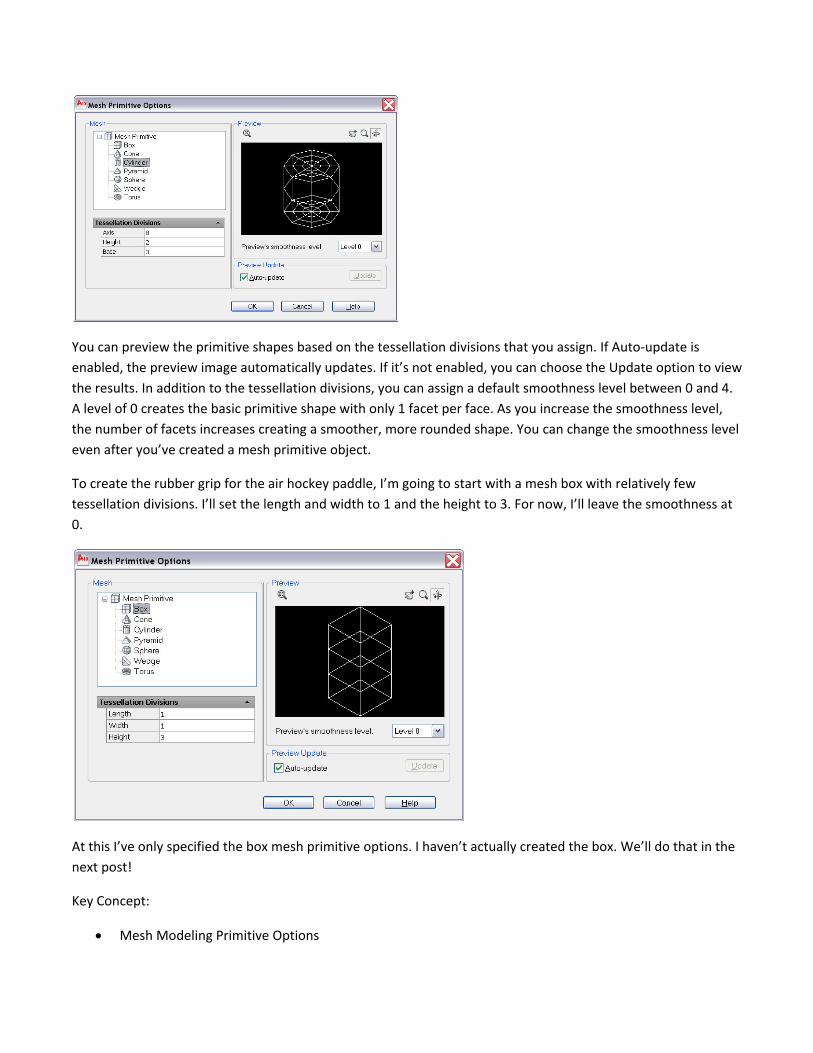
The 3D Modeling workspace in AutoCAD 2010 includes a new Mesh Modeling ribbon tab. The Mesh Modeling
tab has six panels including the Primitives panel. Notice the small arrow icon in the lower right corner of the
Primitives panel. You’ll see the same icon in many other panels throughout the AutoCAD ribbon. These icons
launch relevant dialog boxes for each specific panel. Clicking the icon in the Primitives panel opens the Mesh
Primitive Options dialog box.
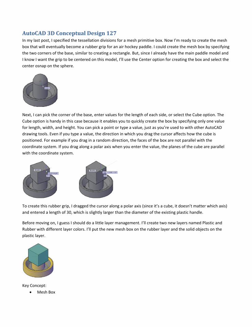
The Mesh Primitive Options dialog box enables you to specify the number of tessellation divisions for the mesh
primitives (box, cone, etc) you create. The tessellation options vary for the different types of primitives. For
example, the tessellation divisions for a box are length, width, and height whereas the divisions for a cylinder
are axis, height, and base. The number of tessellation divisions defines the editable faces on each surface. A
cylinder with 8 axis, 2 height, and 3 base tessellation divisions, for example, has 24 faces on each of the top and
bottom surfaces and 16 faces around the side.
You can preview the primitive shapes based on the tessellation divisions that you assign. If Auto‐update is
enabled, the preview image automatically updates. If it’s not enabled, you can choose the Update option to view
the results. In addition to the tessellation divisions, you can assign a default smoothness level between 0 and 4.
A level of 0 creates the basic primitive shape with only 1 facet per face. As you increase the smoothness level,
the number of facets increases creating a smoother, more rounded shape. You can change the smoothness level
even after you’ve created a mesh primitive object.
To create the rubber grip for the air hockey paddle, I’m going to start with a mesh box with relatively few
tessellation divisions. I’ll set the length and width to 1 and the height to 3. For now, I’ll leave the smoothness at
0.
At this I’ve only specified the box mesh primitive options. I haven’t actually created the box. We’ll do that in the
next post!
Key Concept:
Mesh Modeling Primitive Options
AutoCAD 3D Conceptual Design 127 In my last post, I specified the tessellation divisions for a mesh primitive box. Now I’m ready to create the mesh
box that will eventually become a rubber grip for an air hockey paddle. I could create the mesh box by specifying
the two corners of the base, similar to creating a rectangle. But, since I already have the main paddle model and
I know I want the grip to be centered on this model, I’ll use the Center option for creating the box and select the
center osnap on the sphere.
Next, I can pick the corner of the base, enter values for the length of each side, or select the Cube option. The
Cube option is handy in this case because it enables you to quickly create the box by specifying only one value
for length, width, and height. You can pick a point or type a value, just as you’re used to with other AutoCAD
drawing tools. Even if you type a value, the direction in which you drag the cursor affects how the cube is
positioned. For example if you drag in a random direction, the faces of the box are not parallel with the
coordinate system. If you drag along a polar axis when you enter the value, the planes of the cube are parallel
with the coordinate system.
To create this rubber grip, I dragged the cursor along a polar axis (since it’s a cube, it doesn’t matter which axis)
and entered a length of 30, which is slightly larger than the diameter of the existing plastic handle.
Before moving on, I guess I should do a little layer management. I’ll create two new layers named Plastic and
Rubber with different layer colors. I’ll put the new mesh box on the rubber layer and the solid objects on the
plastic layer.
Key Concept:
Mesh Box
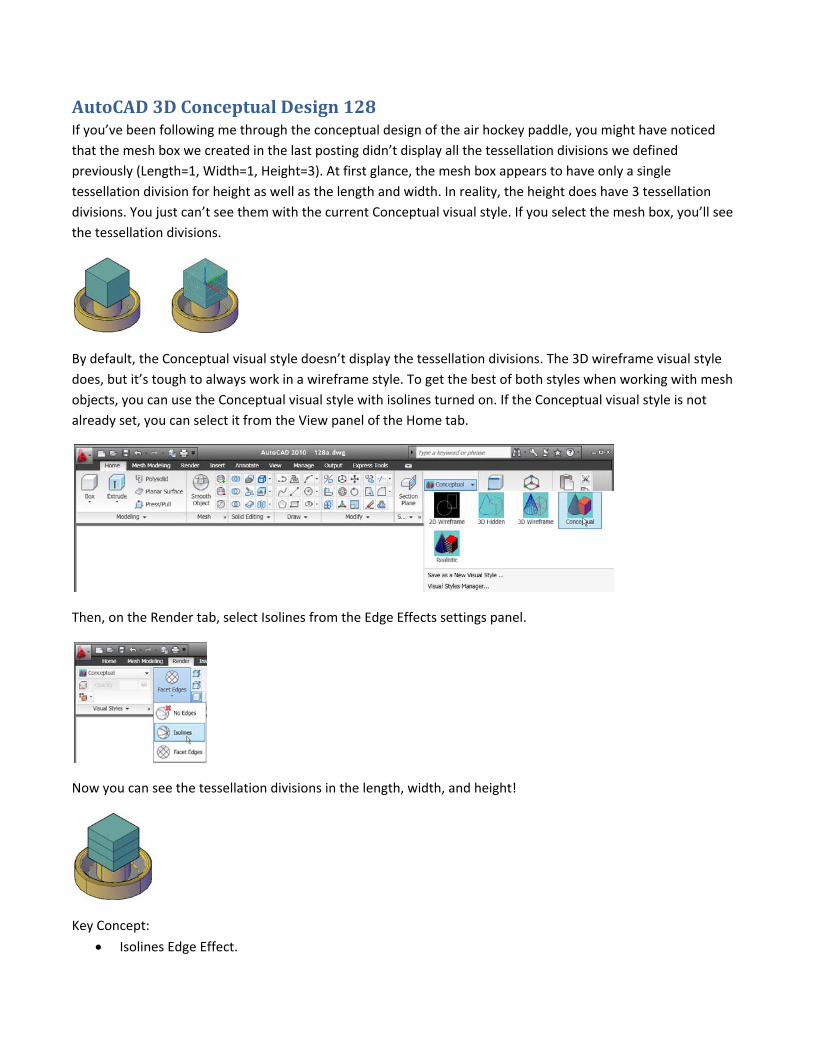
AutoCAD 3D Conceptual Design 128 If you’ve been following me through the conceptual design of the air hockey paddle, you might have noticed
that the mesh box we created in the last posting didn’t display all the tessellation divisions we defined
previously (Length=1, Width=1, Height=3). At first glance, the mesh box appears to have only a single
tessellation division for height as well as the length and width. In reality, the height does have 3 tessellation
divisions. You just can’t see them with the current Conceptual visual style. If you select the mesh box, you’ll see
the tessellation divisions.
By default, the Conceptual visual style doesn’t display the tessellation divisions. The 3D wireframe visual style
does, but it’s tough to always work in a wireframe style. To get the best of both styles when working with mesh
objects, you can use the Conceptual visual style with isolines turned on. If the Conceptual visual style is not
already set, you can select it from the View panel of the Home tab.
Then, on the Render tab, select Isolines from the Edge Effects settings panel.
Now you can see the tessellation divisions in the length, width, and height!
Key Concept:
Isolines Edge Effect.
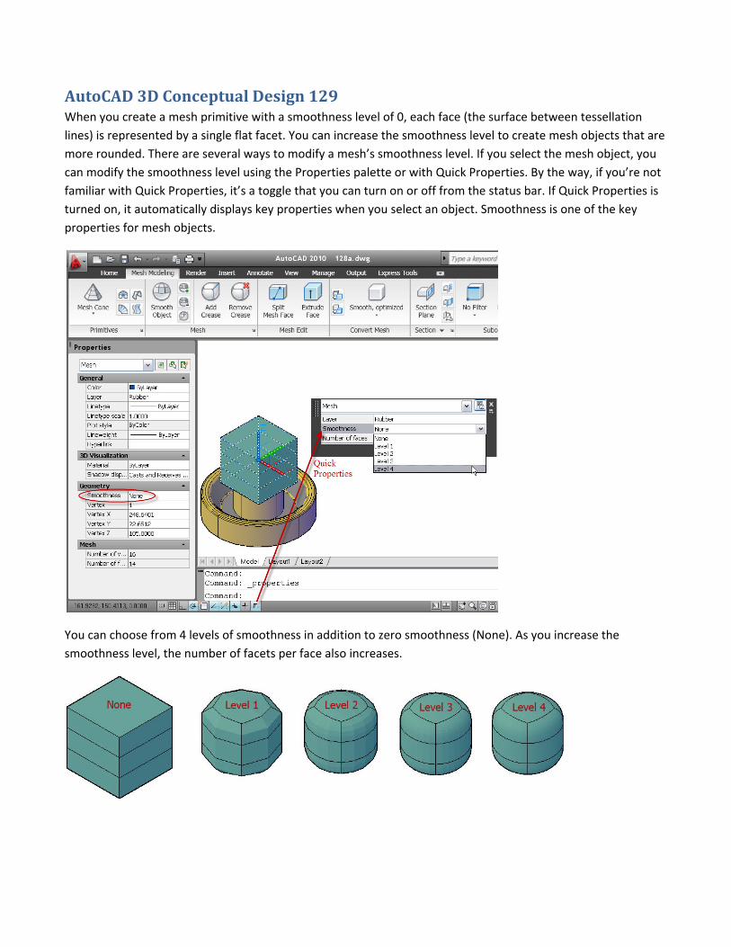
AutoCAD 3D Conceptual Design 129 When you create a mesh primitive with a smoothness level of 0, each face (the surface between tessellation
lines) is represented by a single flat facet. You can increase the smoothness level to create mesh objects that are
more rounded. There are several ways to modify a mesh’s smoothness level. If you select the mesh object, you
can modify the smoothness level using the Properties palette or with Quick Properties. By the way, if you’re not
familiar with Quick Properties, it’s a toggle that you can turn on or off from the status bar. If Quick Properties is
turned on, it automatically displays key properties when you select an object. Smoothness is one of the key
properties for mesh objects.
You can choose from 4 levels of smoothness in addition to zero smoothness (None). As you increase the
smoothness level, the number of facets per face also increases.
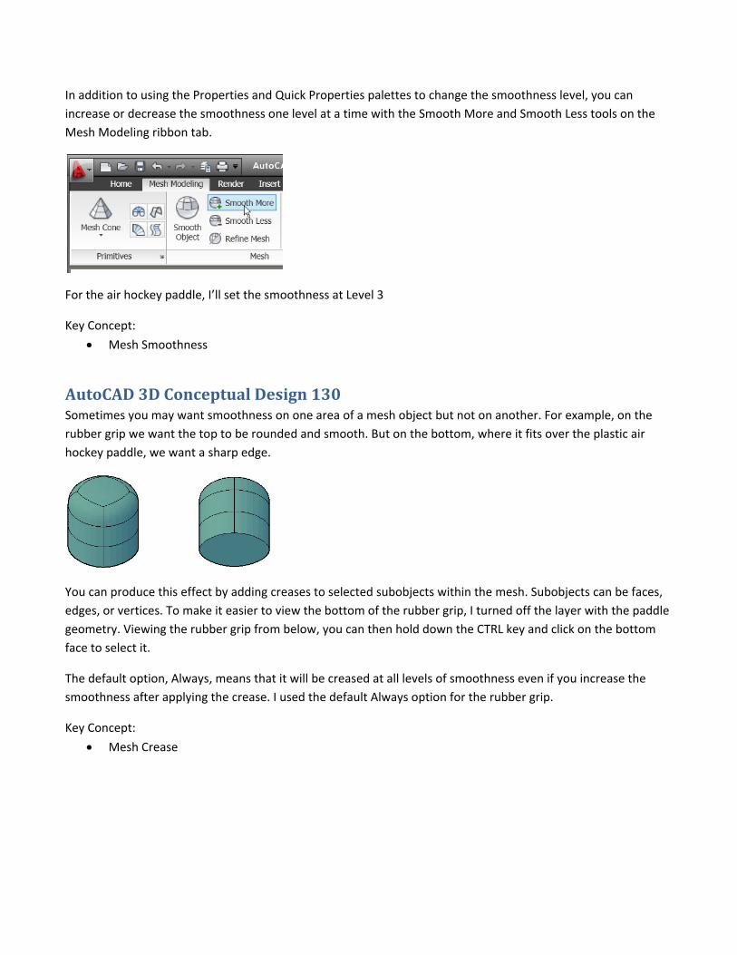
In addition to using the Properties and Quick Properties palettes to change the smoothness level, you can
increase or decrease the smoothness one level at a time with the Smooth More and Smooth Less tools on the
Mesh Modeling ribbon tab.
For the air hockey paddle, I’ll set the smoothness at Level 3
Key Concept:
Mesh Smoothness
AutoCAD 3D Conceptual Design 130 Sometimes you may want smoothness on one area of a mesh object but not on another. For example, on the
rubber grip we want the top to be rounded and smooth. But on the bottom, where it fits over the plastic air
hockey paddle, we want a sharp edge.
You can produce this effect by adding creases to selected subobjects within the mesh. Subobjects can be faces,
edges, or vertices. To make it easier to view the bottom of the rubber grip, I turned off the layer with the paddle
geometry. Viewing the rubber grip from below, you can then hold down the CTRL key and click on the bottom
face to select it.
The default option, Always, means that it will be creased at all levels of smoothness even if you increase the
smoothness after applying the crease. I used the default Always option for the rubber grip.
Key Concept:
Mesh Crease
AutoCAD 3D Conceptual Design 131 The top of the rubber grip is nice and rounded but I’d like to make it a little larger to fit better with an adult
hand. To scale the top of the rubber grip, I’ll use the 3D gizmo. The gizmo is a handy 3D editing tool that was
first introduced in AutoCAD 2007 and was dramatically enhanced in AutoCAD 2010. If you’re modeling in 3D
(since AutoCAD 2007) but haven’t yet tried this gizmo, take a few minutes to check it out. You’ll wonder how
you lived without it.
Before editing the rubber grip, I’ll turn on the Plastic layer because I want to use the Center object snap of the
sphere as my base point for scaling the grip.
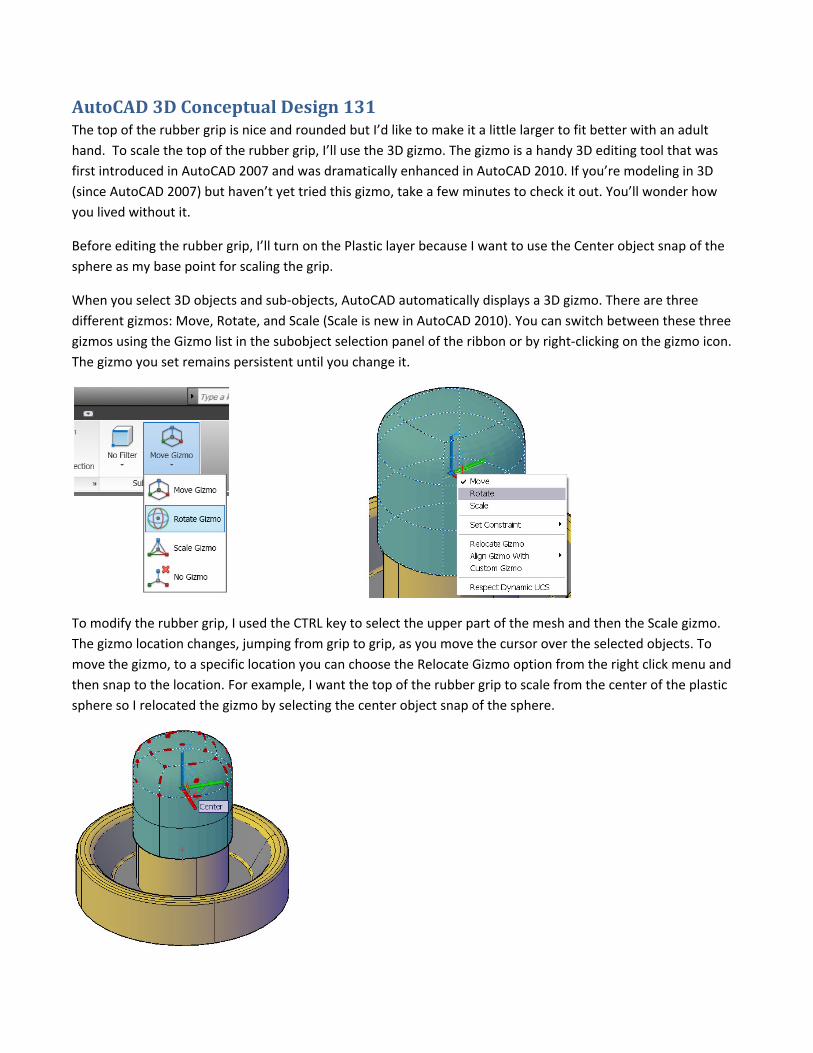
When you select 3D objects and sub‐objects, AutoCAD automatically displays a 3D gizmo. There are three
different gizmos: Move, Rotate, and Scale (Scale is new in AutoCAD 2010). You can switch between these three
gizmos using the Gizmo list in the subobject selection panel of the ribbon or by right‐clicking on the gizmo icon.
The gizmo you set remains persistent until you change it.
To modify the rubber grip, I used the CTRL key to select the upper part of the mesh and then the Scale gizmo.
The gizmo location changes, jumping from grip to grip, as you move the cursor over the selected objects. To
move the gizmo, to a specific location you can choose the Relocate Gizmo option from the right click menu and
then snap to the location. For example, I want the top of the rubber grip to scale from the center of the plastic
sphere so I relocated the gizmo by selecting the center object snap of the sphere.
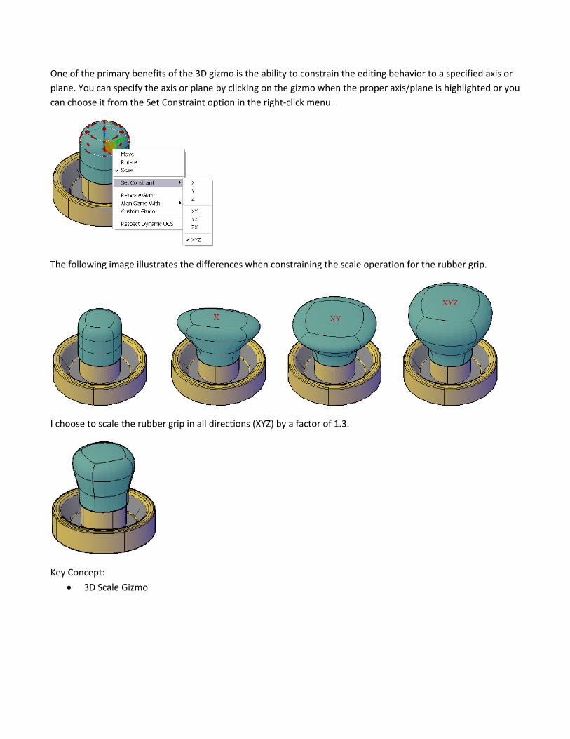
One of the primary benefits of the 3D gizmo is the ability to constrain the editing behavior to a specified axis or
plane. You can specify the axis or plane by clicking on the gizmo when the proper axis/plane is highlighted or you
can choose it from the Set Constraint option in the right‐click menu.
The following image illustrates the differences when constraining the scale operation for the rubber grip.
I choose to scale the rubber grip in all directions (XYZ) by a factor of 1.3.
Key Concept:
3D Scale Gizmo
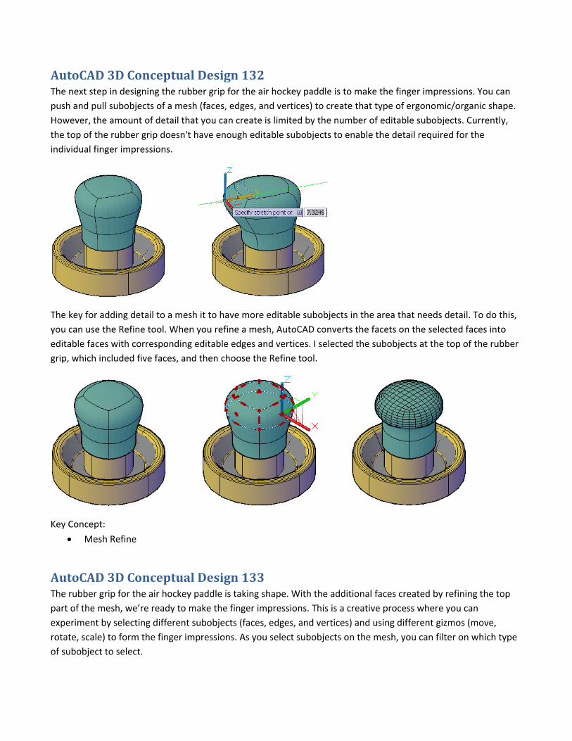
AutoCAD 3D Conceptual Design 132 The next step in designing the rubber grip for the air hockey paddle is to make the finger impressions. You can
push and pull subobjects of a mesh (faces, edges, and vertices) to create that type of ergonomic/organic shape.
However, the amount of detail that you can create is limited by the number of editable subobjects. Currently,
the top of the rubber grip doesn't have enough editable subobjects to enable the detail required for the
individual finger impressions.
The key for adding detail to a mesh it to have more editable subobjects in the area that needs detail. To do this,
you can use the Refine tool. When you refine a mesh, AutoCAD converts the facets on the selected faces into
editable faces with corresponding editable edges and vertices. I selected the subobjects at the top of the rubber
grip, which included five faces, and then choose the Refine tool.
Key Concept:
Mesh Refine
AutoCAD 3D Conceptual Design 133 The rubber grip for the air hockey paddle is taking shape. With the additional faces created by refining the top
part of the mesh, we’re ready to make the finger impressions. This is a creative process where you can
experiment by selecting different subobjects (faces, edges, and vertices) and using different gizmos (move,
rotate, scale) to form the finger impressions. As you select subobjects on the mesh, you can filter on which type
of subobject to select.
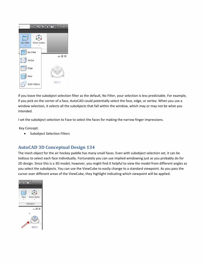
If you leave the subobject selection filter as the default, No Filter, your selection is less predictable. For example,
if you pick on the corner of a face, AutoCAD could potentially select the face, edge, or vertex. When you use a
window selection, it selects all the subobjects that fall within the window, which may or may not be what you
intended.
I set the subobject selection to Face to select the faces for making the narrow finger impressions.
Key Concept:
Subobject Selection Filters
AutoCAD 3D Conceptual Design 134 The mesh object for the air hockey paddle has many small faces. Even with subobject selection set, it can be
tedious to select each face individually. Fortunately you can use implied windowing just as you probably do for
2D design. Since this is a 3D model, however, you might find it helpful to view the model from different angles as
you select the subobjects. You can use the ViewCube to easily change to a standard viewpoint. As you pass the
cursor over different areas of the ViewCube, they highlight indicating which viewpoint will be applied.
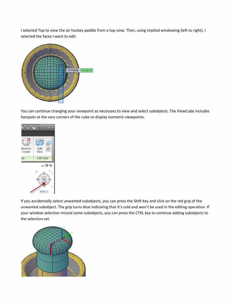
I selected Top to view the air hockey paddle from a top view. Then, using implied windowing (left to right), I
selected the faces I want to edit.
You can continue changing your viewpoint as necessary to view and select subobjects. The ViewCube includes
hotspots at the very corners of the cube to display isometric viewpoints.
If you accidentally select unwanted subobjects, you can press the Shift key and click on the red grip of the
unwanted subobject. The grip turns blue indicating that it’s cold and won’t be used in the editing operation. If
your window selection missed some subobjects, you can press the CTRL key to continue adding subobjects to
the selection set.
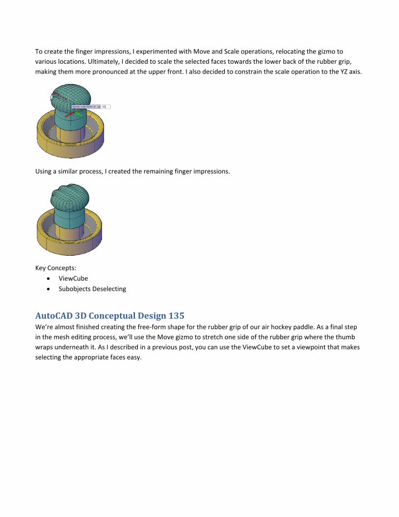
To create the finger impressions, I experimented with Move and Scale operations, relocating the gizmo to
various locations. Ultimately, I decided to scale the selected faces towards the lower back of the rubber grip,
making them more pronounced at the upper front. I also decided to constrain the scale operation to the YZ axis.
Using a similar process, I created the remaining finger impressions.
Key Concepts:
ViewCube
Subobjects Deselecting
AutoCAD 3D Conceptual Design 135 We’re almost finished creating the free‐form shape for the rubber grip of our air hockey paddle. As a final step
in the mesh editing process, we’ll use the Move gizmo to stretch one side of the rubber grip where the thumb
wraps underneath it. As I described in a previous post, you can use the ViewCube to set a viewpoint that makes
selecting the appropriate faces easy.
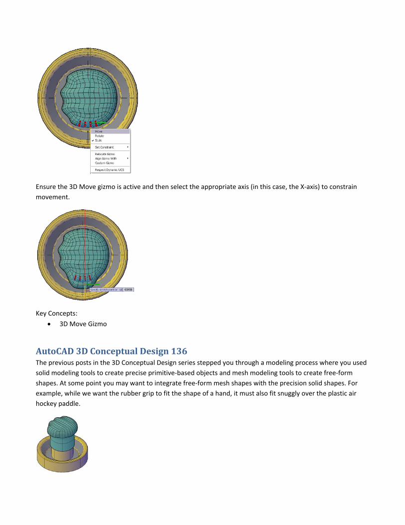
Ensure the 3D Move gizmo is active and then select the appropriate axis (in this case, the X‐axis) to constrain
movement.
Key Concepts:
3D Move Gizmo
AutoCAD 3D Conceptual Design 136 The previous posts in the 3D Conceptual Design series stepped you through a modeling process where you used
solid modeling tools to create precise primitive‐based objects and mesh modeling tools to create free‐form
shapes. At some point you may want to integrate free‐form mesh shapes with the precision solid shapes. For
example, while we want the rubber grip to fit the shape of a hand, it must also fit snuggly over the plastic air
hockey paddle.
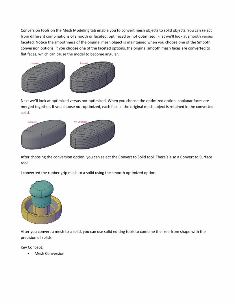
Conversion tools on the Mesh Modeling tab enable you to convert mesh objects to solid objects. You can select
from different combinations of smooth or faceted; optimized or not optimized. First we’ll look at smooth versus
faceted. Notice the smoothness of the original mesh object is maintained when you choose one of the Smooth
conversion options. If you choose one of the faceted options, the original smooth mesh faces are converted to
flat faces, which can cause the model to become angular.
Next we’ll look at optimized versus not optimized. When you choose the optimized option, coplanar faces are
merged together. If you choose not‐optimized, each face in the original mesh object is retained in the converted
solid.
After choosing the conversion option, you can select the Convert to Solid tool. There’s also a Convert to Surface
tool.
I converted the rubber grip mesh to a solid using the smooth optimized option.
After you convert a mesh to a solid, you can use solid editing tools to combine the free‐from shape with the
precision of solids.
Key Concept:
Mesh Conversion
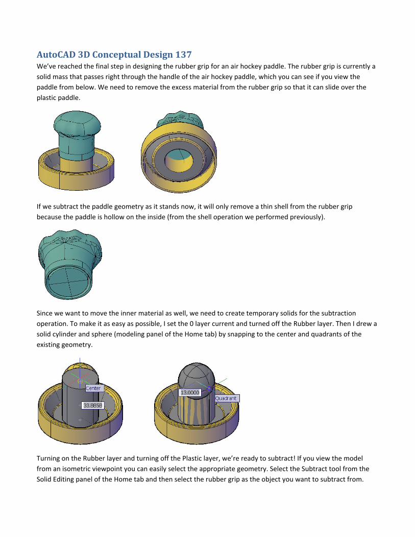
AutoCAD 3D Conceptual Design 137 We’ve reached the final step in designing the rubber grip for an air hockey paddle. The rubber grip is currently a
solid mass that passes right through the handle of the air hockey paddle, which you can see if you view the
paddle from below. We need to remove the excess material from the rubber grip so that it can slide over the
plastic paddle.
If we subtract the paddle geometry as it stands now, it will only remove a thin shell from the rubber grip
because the paddle is hollow on the inside (from the shell operation we performed previously).
Since we want to move the inner material as well, we need to create temporary solids for the subtraction
operation. To make it as easy as possible, I set the 0 layer current and turned off the Rubber layer. Then I drew a
solid cylinder and sphere (modeling panel of the Home tab) by snapping to the center and quadrants of the
existing geometry.
Turning on the Rubber layer and turning off the Plastic layer, we’re ready to subtract! If you view the model
from an isometric viewpoint you can easily select the appropriate geometry. Select the Subtract tool from the
Solid Editing panel of the Home tab and then select the rubber grip as the object you want to subtract from.
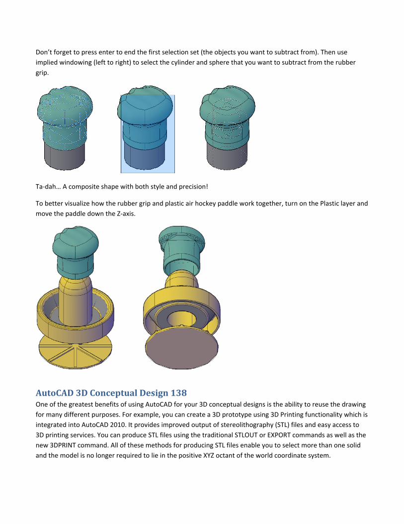
Don’t forget to press enter to end the first selection set (the objects you want to subtract from). Then use
implied windowing (left to right) to select the cylinder and sphere that you want to subtract from the rubber
grip.
Ta‐dah… A composite shape with both style and precision!
To better visualize how the rubber grip and plastic air hockey paddle work together, turn on the Plastic layer and
move the paddle down the Z‐axis.
AutoCAD 3D Conceptual Design 138 One of the greatest benefits of using AutoCAD for your 3D conceptual designs is the ability to reuse the drawing
for many different purposes. For example, you can create a 3D prototype using 3D Printing functionality which is
integrated into AutoCAD 2010. It provides improved output of stereolithography (STL) files and easy access to
3D printing services. You can produce STL files using the traditional STLOUT or EXPORT commands as well as the
new 3DPRINT command. All of these methods for producing STL files enable you to select more than one solid
and the model is no longer required to lie in the positive XYZ octant of the world coordinate system.
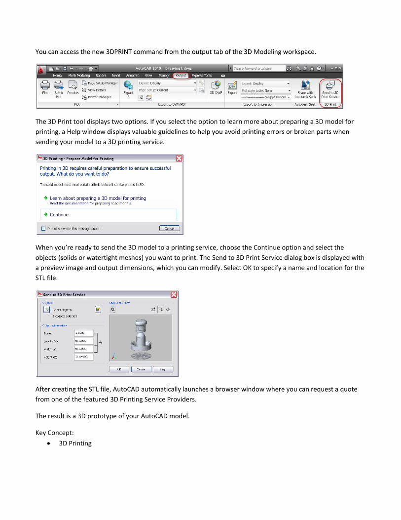
You can access the new 3DPRINT command from the output tab of the 3D Modeling workspace.
The 3D Print tool displays two options. If you select the option to learn more about preparing a 3D model for
printing, a Help window displays valuable guidelines to help you avoid printing errors or broken parts when
sending your model to a 3D printing service.
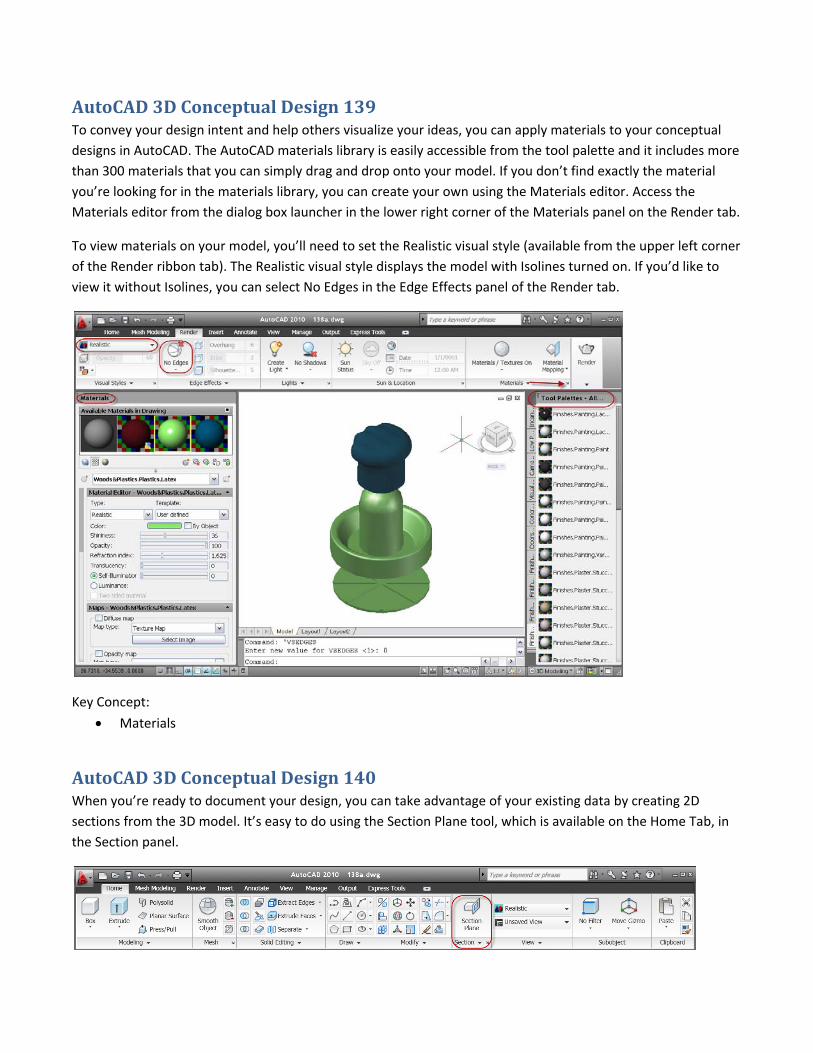
When you’re ready to send the 3D model to a printing service, choose the Continue option and select the
objects (solids or watertight meshes) you want to print. The Send to 3D Print Service dialog box is displayed with
a preview image and output dimensions, which you can modify. Select OK to specify a name and location for the
STL file.
After creating the STL file, AutoCAD automatically launches a browser window where you can request a quote
from one of the featured 3D Printing Service Providers.
The result is a 3D prototype of your AutoCAD model.
Key Concept:
3D Printing
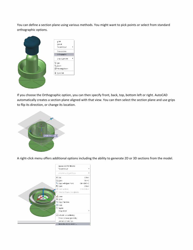
AutoCAD 3D Conceptual Design 139 To convey your design intent and help others visualize your ideas, you can apply materials to your conceptual
designs in AutoCAD. The AutoCAD materials library is easily accessible from the tool palette and it includes more
than 300 materials that you can simply drag and drop onto your model. If you don’t find exactly the material
you’re looking for in the materials library, you can create your own using the Materials editor. Access the
Materials editor from the dialog box launcher in the lower right corner of the Materials panel on the Render tab.
To view materials on your model, you’ll need to set the Realistic visual style (available from the upper left corner
of the Render ribbon tab). The Realistic visual style displays the model with Isolines turned on. If you’d like to
view it without Isolines, you can select No Edges in the Edge Effects panel of the Render tab.
Key Concept:
Materials
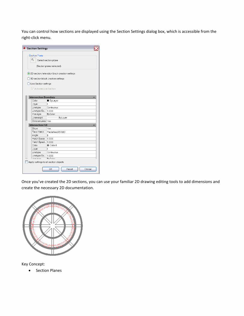
AutoCAD 3D Conceptual Design 140 When you’re ready to document your design, you can take advantage of your existing data by creating 2D
sections from the 3D model. It’s easy to do using the Section Plane tool, which is available on the Home Tab, in
the Section panel.
You can define a section plane using various methods. You might want to pick points or select from standard
orthographic options.
If you choose the Orthographic option, you can then specify front, back, top, bottom left or right. AutoCAD
automatically creates a section plane aligned with that view. You can then select the section plane and use grips
to flip its direction, or change its location.
A right‐click menu offers additional options including the ability to generate 2D or 3D sections from the model.
You can control how sections are displayed using the Section Settings dialog box, which is accessible from the
right‐click menu.
Once you’ve created the 2D sections, you can use your familiar 2D drawing editing tools to add dimensions and
create the necessary 2D documentation.
Key Concept:
Section Planes


