45 26. ročník - č. 1/2017 1 NEJISTOTY INŽENÝRSKÉ GEODÉZIE Zeměměřické činnosti, které doprovázejí inženýrskou výstavbu a výstavbu obecně, spadají do oboru geodézie, který se nazývá inženýrská geodézie. Jedním z několika základních postupů používaných v inženýrské geodézii je práce s úhly, resp. směry a délkami, které jsou dále matematicky zpracová- vané v euklidovském metrickém dvourozměrném prostoru (klasický pravoúhlý souřadnicový systém). Výsledkem potom může být buď jejich zpracování do souřadnic a porovnání se skutečností – kontrolní měření skutečnosti, nebo naopak výpočet těchto hodnot ze souřadnic a vytyčení oněch souřad- nic pomocí směrů a délek v terénu. V dnešní době je „mate- matická“ část zajištěna výpočetními programy, které se rozví- její již několik desetiletí, a za poslední dvě dekády neustálé akcelerace elektronizace a vývoje výpočetních komponentů, ze kterých jsou dnes totální stanice vyráběny, se staly běžnou součástí každé kvalitní totální stanice. Výše popsané postupy se jeví v teoretické rovině jako relativ- ně jednoduché, onu jednoduchost však významně narušují svým vlivem minimálně dvě skutečnosti: nepřesnosti (nejistoty, chyby) dat a věčná snaha o zmírnění jejich vlivu na výsledky našich čin- ností. Nejistoty, se kterými se geodeti potkávají a jejichž vznik se připisuje náhodným jevům, jsou statisticky popsány Gaussovým normálním rozdělením pravděpodobnosti se svými charakteristi- kami: jedná se především o střední hodnotu a směrodatnou odchylku, která definuje její interval spolehlivosti [1]. 1.1 Nejistota podkladu pro měření V současnosti je geodet bez referenčního bodového pole naprosto „slepý“. Proto má každá stavba k dispozici body 1 UNCERTAINTIES OF ENGINEERING SURVEYING Land surveying activities attending the civil engineering development and building in general come under the survey- ing branch called the engineering surveying. One of several basic procedures used in engineering surveying is the work with angles or directions and distances, which are further pro- cessed mathematically in the Euclidean metric two-dimensio- nal space (the classical rectangular coordinate system). The result can be either their processing into coordinates and the comparison with the reality – check measurements of reality, or vice versa, the calculation of those values from the coordi- nates and setting out those coordinates by directions and distances in the field. At present, the “mathematical” part is ensured by mathematical programs, which have been develo- ping already several decades. During the past two decades of continual acceleration of computerisation and development of calculation components from which the total stations are cur- rently manufactured they have become parts of each good- quality total station. The above described procedures appear, at a theoretical level, to be relatively simple, but the simplicity is significant- ly disturbed by the influence of minimally two facts: inaccura- cies (uncertainties, errors) of data and the eternal effort to mediate their influence on the results of our activities. The uncertainties surveyors encounter and the origination of which is attributed to random events are statistically described by the Gaussian normal probability distribution with its characteris- tics, namely, in the first place, the mean value and the standard deviation defining its confidence interval [1]. GEODETICKÁ ODCHYLKA NA PRORÁŽCE PODZEMNÍCH LINIOVÝCH DĚL SURVEY DEVIATION AFTER BREAKTHROUGH OF UNDERGROUND LINEAR WORKINGS PETR HLAVÁČEK ABSTRAKT Geodetické práce jsou nezbytnou součástí výstavby podzemních liniových děl a jejich úkolem je mimo jiné, aby se podzemní dílo nacházelo na správném místě a mělo správný tvar. Pro zajištění správného umístění stavby a vedení ražeb správným směrem v souladu s projektovou dokumentací za účelem dosažení nejmenší možné prorážkové odchylky je třeba vytvořit a udržovat základ- ní vytyčovací síť bodů na portálech a provádět usměrňovací měření, při kterých jsou určovány souřadnice bodů pomocné vytyčo- vací sítě v podzemí. Tato činnost, která patří mezi nejnáročnější geodetické práce prováděné s velmi vysokou přesností, je zatíže- na objektivními negativními vlivy z nepřesnosti měřického vybavení a z měření prováděného ve fyzikálně nehomogenním prostře- dí. Článek tyto vlivy popisuje a představuje matematický nástroj, kterým je možné předpovědět velikost prorážkové odchylky již v počátečních fázích výstavby. ABSTRACT Surveying is a necessary part of the construction of underground linear workings. Its task is, among other things, to ensure that the underground working is built in a correct place and has a correct geometry. It is necessary for the purpose of ensuring the correct position and correct direction of the tunnel excavation in compliance with design documents so that as small as possible breakthrough deviation is achieved to create and maintain the basic setting out network of points at portals and conduct orienta- tion (guidance) measurements during which coordinates of the points of the auxiliary setting out network in the underground are determined. This activity, which belongs among the most complex survey operations carried out with very high precision, is affec- ted by objective negative effects associated with the precision of measurement equipment and measurement carried out in physi- cally inhomogeneous environment. The paper describes those effects and introduces a mathematical tool, the use of which allows for predicting the breakthrough deviation as early as the initial phases of construction.
Transcript
45
26. ročník - č. 1/2017
1 NEJISTOTY INŽENÝRSKÉ GEODÉZIE
Zeměměřické činnosti, které doprovázejí inženýrskouvýstavbu a výstavbu obecně, spadají do oboru geodézie, kterýse nazývá inženýrská geodézie. Jedním z několika základníchpostupů používaných v inženýrské geodézii je práce s úhly,resp. směry a délkami, které jsou dále matematicky zpracová-vané v euklidovském metrickém dvourozměrném prostoru(klasický pravoúhlý souřadnicový systém). Výsledkem potommůže být buď jejich zpracování do souřadnic a porovnání seskutečností – kontrolní měření skutečnosti, nebo naopakvýpočet těchto hodnot ze souřadnic a vytyčení oněch souřad-nic pomocí směrů a délek v terénu. V dnešní době je „mate-matická“ část zajištěna výpočetními programy, které se rozví-její již několik desetiletí, a za poslední dvě dekády neustáléakcelerace elektronizace a vývoje výpočetních komponentů,ze kterých jsou dnes totální stanice vyráběny, se staly běžnousoučástí každé kvalitní totální stanice.
Výše popsané postupy se jeví v teoretické rovině jako relativ-ně jednoduché, onu jednoduchost však významně narušují svýmvlivem minimálně dvě skutečnosti: nepřesnosti (nejistoty, chyby)dat a věčná snaha o zmírnění jejich vlivu na výsledky našich čin-ností. Nejistoty, se kterými se geodeti potkávají a jejichž vznik sepřipisuje náhodným jevům, jsou statisticky popsány Gaussovýmnormálním rozdělením pravděpodobnosti se svými charakteristi-kami: jedná se především o střední hodnotu a směrodatnouodchylku, která definuje její interval spolehlivosti [1].1.1 Nejistota podkladu pro měření
V současnosti je geodet bez referenčního bodového polenaprosto „slepý“. Proto má každá stavba k dispozici body
1 UNCERTAINTIES OF ENGINEERING SURVEYING
Land surveying activities attending the civil engineeringdevelopment and building in general come under the survey-ing branch called the engineering surveying. One of severalbasic procedures used in engineering surveying is the workwith angles or directions and distances, which are further pro-cessed mathematically in the Euclidean metric two-dimensio-nal space (the classical rectangular coordinate system). Theresult can be either their processing into coordinates and thecomparison with the reality – check measurements of reality,or vice versa, the calculation of those values from the coordi-nates and setting out those coordinates by directions anddistances in the field. At present, the “mathematical” part isensured by mathematical programs, which have been develo-ping already several decades. During the past two decades ofcontinual acceleration of computerisation and development ofcalculation components from which the total stations are cur-rently manufactured they have become parts of each good-quality total station.
The above described procedures appear, at a theoreticallevel, to be relatively simple, but the simplicity is significant-ly disturbed by the influence of minimally two facts: inaccura-cies (uncertainties, errors) of data and the eternal effort tomediate their influence on the results of our activities. Theuncertainties surveyors encounter and the origination of whichis attributed to random events are statistically described by theGaussian normal probability distribution with its characteris-tics, namely, in the first place, the mean value and the standarddeviation defining its confidence interval [1].
GEODETICKÁ ODCHYLKA NA PRORÁŽCE PODZEMNÍCH LINIOVÝCH DĚLSURVEY DEVIATION AFTER BREAKTHROUGH OF UNDERGROUND
LINEAR WORKINGS
PETR HLAVÁČEK
ABSTRAKT
Geodetické práce jsou nezbytnou součástí výstavby podzemních liniových děl a jejich úkolem je mimo jiné, aby se podzemní dílonacházelo na správném místě a mělo správný tvar. Pro zajištění správného umístění stavby a vedení ražeb správným směremv souladu s projektovou dokumentací za účelem dosažení nejmenší možné prorážkové odchylky je třeba vytvořit a udržovat základ-ní vytyčovací síť bodů na portálech a provádět usměrňovací měření, při kterých jsou určovány souřadnice bodů pomocné vytyčo-vací sítě v podzemí. Tato činnost, která patří mezi nejnáročnější geodetické práce prováděné s velmi vysokou přesností, je zatíže-na objektivními negativními vlivy z nepřesnosti měřického vybavení a z měření prováděného ve fyzikálně nehomogenním prostře-dí. Článek tyto vlivy popisuje a představuje matematický nástroj, kterým je možné předpovědět velikost prorážkové odchylky jižv počátečních fázích výstavby.
ABSTRACT
Surveying is a necessary part of the construction of underground linear workings. Its task is, among other things, to ensure thatthe underground working is built in a correct place and has a correct geometry. It is necessary for the purpose of ensuring thecorrect position and correct direction of the tunnel excavation in compliance with design documents so that as small as possiblebreakthrough deviation is achieved to create and maintain the basic setting out network of points at portals and conduct orienta-tion (guidance) measurements during which coordinates of the points of the auxiliary setting out network in the underground aredetermined. This activity, which belongs among the most complex survey operations carried out with very high precision, is affec-ted by objective negative effects associated with the precision of measurement equipment and measurement carried out in physi-cally inhomogeneous environment. The paper describes those effects and introduces a mathematical tool, the use of which allowsfor predicting the breakthrough deviation as early as the initial phases of construction.
46
26. ročník - č. 1/2017
základní vytyčovací sítě (dále ZVS) s jejich souřadnicemi.Tyto souřadnice, které jsou pro každou geodetickou činnostzásadním podkladem pro práci, jsou vždy zatíženéurčitou nejistotou (přesností) z jejich určení, charakterizova-nou jejich směrodatnou polohovou odchylkou. Zde začínánejistota každého geodeta.
Pokud jsou k dispozici souřadnice „pevného“ bodu se smě-rodatnou polohovou odchylkou (přesností) o velikosti 5 mm,znamená to, že když kolem pozice tohoto bodu vytvořímekružnici o poloměru 5 mm (průměr 10 mm), tak tato kružnicedefinuje plochu, ve které se ten, venku se nacházející, reálnýbod může může ve skutečnosti teoreticky v souřadnicové sou-stavě na hladině pravděpodobnosti 68 % nacházet. Jinýmislovy to znamená, že jakékoli souřadnice z této kružnice majína dané hladině pravděpodobnosti pro tento bod stejnou plat-nost. Pokud chceme zvýšit hladinu pravděpodobnosti na 99,7%, musíme hodnotu směrodatné polohové odchylky (5 mm)vynásobit koeficientem 3 a získáváme kružnici o poloměru15 mm a průměru 30 mm.
Hodnotu 5 mm uvádíme jako referenční, protože je možnodosáhnout ji i se středně kvalitním měřickým vybaveníma správnými postupy. Pro tunelové stavby je vhodnější hod-nota relativní směrodatné polohové odchylky souřadnic bodůZVS do 3 mm. Tento nepatrný rozdíl 2 mm znamená ve sku-tečnosti významný nárůst požadavků na vybavení a pečlivostprováděných geodetických prací.1.2 Nejistota v měřickém vybavení
Všechny měřické přístroje bez ohledu na obor měřís určitou chybou (přesností, nejistotou) a je tomu tak samo-zřejmě i u geodetického měřického vybavení. I přes velkýrozvoj technologií, využívajících laserové skenování nebopříjem satelitního signálu, je dosud nejčastěji používanýmgeodetickým měřickým vybavením tzv. totální stanice,velmi sofistikované elektrooptické zařízení na měření vzdá-leností a vodorovných a výškových směrů, ze kterých jemožno dopočítat úhly. Přesnost u totální stanice (obr. 1) jeudávána především přesností úhlového měření daného smě-rodatnou odchylkou měřeného směru a přesností měřenídélek, definovaného směrodatnou odchylkou rozdělenou nadvě složky a udávanou tvarem např. 2+1ppm, což znamená,že každou změřenou vzdálenost je třeba zohlednit složkouchyby až do výše 2 mm bez ohledu na její délku a složkouchyby, která je závislá na délce změřené vzdálenosti, zde1 mm na změřenou délku 1 km. Tyto výrobcem deklaro vanéhodnoty však platí pouze za určitých podmínek, především
1.1 Uncertainty of the measurement basis data
A surveyor without reference geodetic control is currentlytotally “blind”. For that reason each construction project hasthe basic setting-out net (BSN) with the coordinates of pointsavailable. These coordinates, which are the basic basis datafor the work for any surveying activity, are always affected bycertain uncertainty (inaccuracy) following from their determi-nation, which is characterised by their standard positionaldeviation. This is where the uncertainty of any surveyorbegins.
If the standard positional deviation of coordinates ofa “fixed” point available is equal to 5mm, it means that if wecreate a 5mm radius (10mm diameter) circle around the pointin situ, this circle defines the area within which this point mayin reality theoretically lie at the probability level of 68%. Inother words, it means that the applicability of any coordinatewithin this circle on the probability level determined for thispoint is the same. If we want to increase the probability levelto 99.7%, we have to multiply the standard positional deviati-on value (5mm) by the coefficient 3 and we will obtaina 15mm radius (30mm-diameter) circle. We present the 5mmvalue as a reference value because it can be achieved evenusing medium quality measurement equipment and correctprocedures.
For tunnel structures more suitable is the relative standardpositional deviation of coordinates of BSN points up to 3mm.This slight 2mm difference means in reality a really significantincrease in requirements for the equipment and carefulness ofcarrying out survey operations. 1.2 Uncertainty in surveying equipment
All measuring apparatuses, irrespective of the measure-ment branch, measure with a certain error (accuracy, uncer-tainty) and this fact certainly applies even to survey measu-rement equipment. Even despite the major development oftechnologies using laser scanning or satellite signal recep-tion, the so far most frequently used survey measurementequipment is the so-called total station, which is very sop-histicated electro-optical equipment for measuring distan-ces and horizontal and vertical directions, from which it ispossible to finish the calculation of angles. The accuracy inthe case of a total station (see Fig. 1) is determined first ofall by the accuracy of measuring of angles defined by thestandard deviation of the direction being measured and theaccuracy of the measurement of lengths, which is given bythe standard deviation divided into two components andpresented in the form of, for example, 2+1ppm, whichmeans that an error of up to 2mm has to be taken intoaccount for each of the measured distances, irrespective ofits length, as well as the error component depending on thelength of the measured distance, here 1mm per the measu-red length of 1km. However, these values declared by themanufacturer are applicable only under certain conditions,first of all in a homogeneous laboratory optical environ-ment (see below).
The measurement equipment can be purchased at variouslevels of the accuracy of measured quantities which is guaran-teed by the manufacturer. A correlation applies that the moreaccurate equipment the higher the purchase price. Despite thisfact, even with the most accurate equipment, the surveyor hasto begin from the theory that no measured value agrees withreality and, as mentioned below, increasing the quantity of
Obr. 1 Totální staniceFig. 1 Total station
47
26. ročník - č. 1/2017
pak v homogenním laboratorním optickém prostředí (vizdále).
Měřické vybavení je možné pořídit v různých úrovníchpřesností měřených veličin, garantovaných výrobcem a platíúměra, že čím přesnější vybavení je, tím je vyšší pořizovacícena. Přesto i s nejpřesnějším vybavením geodet musí vychá-zet z teorie, že žádná změřená hodnota neodpovídá skuteč-nosti a jak bude dále zmíněno, přichází na řadu navyšováníopakování stejných měření, jehož účelem je hledání co nej-lepší aproximace skutečnosti s co nejmenší nejistotou (tedys co nejvyšší přesností).1.3 Nejistota z měření ve fyzikálním prostředí
Geodézie využívá pro své účely především zákony optiky.V případě měření úhlů, resp. směrů, je přijímán v totální sta-nici světelný paprsek (elektromagnetické vlnění vnímatelnélidským okem) vyzařovaný cílem. V případě měření vzdále-ností je měřicím zařízením elektromagnetické vlnění vyslanék cíli, tam se odráží a je zpětně přijímáno a vyhodnoceno.
V obou případech se elektromagnetické vlnění pohybujev optickém prostředí. V něm obecně platí zásada, že se optic-ký paprsek šíří z bodu A do bodu B tou nejrychlejší cestou,která ovšem nemusí být totožná s tou geometricky nejkratší –přímkou. Na trasu nejrychlejší cesty optického paprsku majívýznamný vliv vlastnosti okolního fyzikálního prostředí –především pak teplota vzduchu a atmosférický tlak.
Při měření úhlů, resp. směrů, se tento vliv projevuje ohnutímsvětelného paprsku, a tím i určitým „znehodnocením“ měře-ných hodnot a nazývá se refrakce. Zjednodušeně je možno jejpopsat situací, kdy Slunce při jeho východu a západu díky prů-chodu světelných paprsků několika vrstvami atmosféry o růz-ných fyzikálně-optických vlastnostech na jejich cestě směremod Slunce k Zemi vnímáme na jiné „výšce“ nad horizontem,než na jaké se ve skutečnosti nachází (což je obvykle níže).
repeated identical measurements comes into consideration. Itspurpose is to find the best approximation of the reality, withthe smallest uncertainty possible (i.e. with the highest accu-racy).1.3 Uncertainty from measuring
in a physical environment
Surveying uses primarily the optical laws for its purposes. Inthe case of measuring angles respectively directions, a lightbeam is received in the total station (electromagnetic wavesperceivable by a human eye) emitted from the target. In thecase of measuring distances, the measurement apparatus sendselectromagnetic waves toward the target, where it is reflected.It is received back and assessed.
In both cases the electromagnetic waves move through anoptical environment. A principle generally applies in this envi-ronment that an optical beam propagates itself from point A topoint B along the fastest route, which however does not haveto be identical with the geometrically shortest route – a stra-ight line. The fastest route of the optical beam is significantlyaffected by the properties of the surrounding physical environ-ment – first of all air temperature and atmospheric pressure.
When angles or directions are being measured, this effectmanifests itself by bending the light beam, thus even by cer-tain “devaluation” of the measured values. It is called therefraction. In a simplified way it is possible to describe it asa situation where we perceive the Sun during its rising andsetting at another “height” above the horizon than at whichit is in reality found, usually lower. It is so due to the passa-ge of light beams through several layers of the atmospherefeaturing variable physical-optical properties on their wayfrom the Sun to the Earth. If we wanted to determine this“height” from observer’s location, the determination wouldbe “devaluated” by refraction, which is in the case of objectsobserved outside the atmosphere called atmospheric refrac-tion (see Fig. 2).
Surveyors encounter the common terrestrial refraction,which has one of the greatest negative effects on measure-ments permanently during the surveys. It is true that its effectscan be in certain cases predicted or neglected, but unfortuna-tely, just in the field of engineering surveying used in the con-struction of tunnels, the refraction is one of the most maliciousparameters significantly affecting the uncertainty of results(the magnitude and direction of its influence is nearly impos-sible to reveal). Yet it is just during the construction of tunne-ls where we can encounter it more frequently than anywhereelse, first of all in winter seasons, when its negative influenceis greatest:
• in the areas of tunnel portals when the surveying orienta-tion measurements begin outside, in freezing conditionswith the temperature below the freezing point, and end atthe excavation face, where the temperature can be even30°C; the shorter the distance of the face the greater influ-ence of refraction threatens;
• in the areas of cross passages, where various temperatureair streams are mixed;
• in the surroundings of any construction equipment emit-ting heat to its surroundings during the work;
• even in the areas where different temperature air, forexample from a damaged ventilation duct, freshly appliedshotcrete or newly opened massif (unsupported excavati-on) is mixed with the warm air stabilised inside the tunnel.
Obr. 2 Princip astronomické refrakce: P – pozorovatel, H – skutečná poziceSlunce, H' – zdánlivá pozice Slunce, černé šipky – lom světelného paprsku Fig. 2 Astronomic refraction principle: P – observer, H – actual position ofthe Sun, H' – apparent position of the Sun, black arrows – light beam ref-raction
Pokud bychom chtěli tuto „výšku“ určit z místa pozorovatele,došlo by při jejím určení k „znehodnocení“ refrakcí, která sev případě objektů pozorovaných vně atmosféry nazývá atmo-sférickou (obr. 2).
S běžnou terestrickou refrakcí, která má jeden z největ-ších negativních vlivů na měření, se geodeti při svýchměřeních setkávají neustále. Její účinky je sice možnov určitých případech předvídat nebo zanedbat, ale bohuželprávě v oblasti inženýrské geodézie provozované přivýstavbě tunelů je refrakce jedním z nejzákeřnějších para-metrů významně ovlivňujících nejistotu výsledku (velikosti směr jejího vlivu je téměř nemožné odhalit). A přitomprávě při výstavbě tunelu se s ní můžeme setkat častěji, nežkdekoli jinde, především v zimním období, kdy je její nega-tivní vliv největší:
• v oblasti tunelových portálů, kdy geodetické usměrňova-cí měření začíná venku v mrazivých podmínkách s teplo-tou pod bodem mrazu a končí na čelbě, kde může být tep-lota i přes 30 °C, čím kratší vzdálenost k čelbě, tím většívliv refrakce hrozí;
• v oblasti propojek, kde se mísí vzdušné proudy různýchteplot;
• v okolí každé stavební techniky, která pracuje a přitomvyzařuje do svého okolí teplo;
• i v oblasti, kde se do teplého vzduchu, který je stabilizo-vaný uvnitř tunelu, mísí vzduch jiné teploty napříkladz poškozené lutny, čerstvě nastříkaného betonu nebo čer-stvě otevřeného masivu (nezajištěného výrubu).
Při průchodu optického paprsku popsanými náhlými tepel-nými změnami vzdušných vrstev dochází k jeho nekontrolo-vatelnému a případně i několikanásobnému ohnutí. Pro sníže-ní vlivu refrakce je možné použít určité měřické postupy,ovšem velký význam má především zkušenost měřiče. Při čin-nostech prováděných naší společností jsme se setkali i s ohnu-tím paprsku o přibližně 8 cm na vzdálenosti cca 100 m.
Pro měření vzdáleností je zase využíván princip měření časumezi vysláním a příjmem zpět odraženého elektromagnetické-ho vlnění, jehož rychlost je ovlivňována právě optickýmivlastnostmi prostředí, ve kterém měření probíhá. Platí, že čímhustější prostředí, tím pomalejší je paprsek. O hodnotu vznik-lou tímto vlivem je třeba naměřené vzdálenosti korigovat.
Protože při geodetickém měření na místě výstavby nenínikdy k dispozici ideální homogenní optické prostředí, ve kte-rém by nedocházelo k popsaným jevům, výsledkem těchtoměření potom bohužel nejsou ideální hodnoty úhlů, resp.směrů a vzdáleností, které jsou potřeba pro další matematickázpracování.1.4 Celková nejistota inženýrské geodézie při výstavbě
podzemních liniových děl
Z uvedeného vyplývá, že výsledek práce geodeta přivýstavbě je zatížen nepřesností souřadnic bodů ZVS, nepřes-ností měřického vybaveni deklarovanou výrobcem a ještěk tomu je ovlivněn vlastnostmi okolního fyzikálního prostře-dí při měření. Vzhledem k těmto negativním vlivům na výsle-dek měřických prací, se z geodetů stávají především statistici.Proto jsou nutnou součástí inženýrské geodézie znalostiz oblasti, která se zabývá:
• zpracováním dat opakovaných měření stejných, přede-vším geometrických prvků;
During the optical beam passage through the above-mentio-ned abrupt changes in temperature of air layers, uncontrollableor even multiple bending of the optical beam is encountered. Itis possible to use certain surveying procedures for reducing theinfluence of refraction, but first of all the experience of the sur-veyor is important. During the activities conducted by our com-pany we have encountered the bending of the light beam evenby approximately 8cm over the distance of ca 100m.
Distances are measured using the principle of measuring thetime between sending of the electromagnetic waves and recei-ving the rebound waves back. Their velocity is affected rightby the optical properties of the environment in which the mea-surements are conducted. It is true that the denser environmentthe slower the light beam. The measured distances have to becorrected by the value originating in this way.
Because of the fact that an ideal homogeneous environmentwhere the above-mentioned phenomena do not exist is neveravailable on construction site during the in-situ surveyingmeasurements, those measurements unfortunately result intonon-ideal values of angles and distances required for subsequ-ent mathematical processing.1.4 Overall uncertainty of engineering survey during
the implementation of underground linear workings
It follows from the above-mentioned facts that the result ofsurveyor’s work during the process of construction is loadedby the inaccuracy of coordinates of the BSN points and by thedeclared inaccuracy of the surveying equipment. In addition,the result is affected by the properties of the surrounding phy-sical environment during the survey. With respect to thosenegative effects on the measurement results, surveyors becomefirst of all statisticians. For that reason the knowledge from thefields dealing with the following activities is a necessary partof engineering surveying:
• processing the data obtained by repeated measurements ofidentical elements, mainly of geometrical ones;
• processing the data obtained by various measurement pro-cedures leading to the same result – for example the deter-mination of coordinates of one point using several diffe-rent procedures, which are in addition based on differentbasis data;
• combining the two above-mentioned procedures.All of that is used for the minimisation of the negative
effects on the result and leads to obtaining a result with thebest approximation to the reality and with the lowest possibleuncertainty.
Compared to surveyors working on building sites, surveyorsparticipating on an underground working have another greatdisadvantage: they have no certainty where the excavation isreally located until the breakthrough. The only thing they cando until that time is to carry out guidance measurements withthe care which will allow them to be sufficiently convincedwithin the framework of their experience and possibilities thatthe coordinates of their points of geodetic point field in theunderground, thus also the real location of the mined working,are determined with the highest possible probability and thelowest possible uncertainty, in compliance with design docu-mentation.
Taking into consideration the fact surveyors start the measu-rements from one “fixed” place with some uncertainty (typi-cally for portal BSN) and carry out measurements in the tun-nel the results of which are not unambiguously verifiable at the
49
26. ročník - č. 1/2017
other end until the breakthrough, it is possible to compare thissituation to a moderately elastic lever (analogy to orientationmeasurements from the portal up to the excavation face) elas-tically fixed on one end (the BSN points analogically), whilethe other end hangs freely in the air. The lever deflects in thedirection in which some force acts on it. In addition, the lon-ger lever the higher “lateral forces” (here due to the inaccura-cy of measurements) can act on it.
The resultant pressure, together with the above-mentionedelasticity cases, corresponds to gradual propagation of inaccu-racies from the basis data and measurements. This phenome-non is dealt with by the Law of Propagation of StandardDeviations, see the next chapter 2.
One of the possibilities how to reduce the overall uncertain-ty of the result without which surveyors cannot cope is theimplementation of the above-mentioned measures: repeatingmeasurements of identical elements, applying different proce-dures to obtaining one result and combining both options. Thissystem leads to redundancy of data, which originates at themoment when more data than necessary for the particular pur-pose is available. For simplicity it is possible to use a straightline for explanation in the following text, but in practice thisconcrete example essentially does not occur – coordinates oftwo points are necessary for the mathematical definition of thestraight line and any other point lying on the particular straightline is redundant for the definition.
But, as mentioned above, in the field of surveying the coor-dinates of definition points of a straight line are obtained bya real measurement, which is always loaded by some uncerta-inty, which is transferred on the resultant coordinates; the ina-ccuracy of the result originates in this way. If it is necessary todefine a line on the basis of the points surveyed in this way, itis on the contrary appropriate to survey more such pointswhich are its components to define it as accurately as possib-le. With respect to the inaccuracy of the resulting coordinates,these points do not lie exactly on the particular straight lineand it is necessary to find its best approximation for it. Themore redundant points available the higher redundancy of thesystem. This leads to better approximation to the reality (forthe definition of the required straight line). This is why thesaying “Measure twice and cut once” is more applicable to sur-veying and especially engineering surveying than anywhereelse.
It further applies that the more accurate the result is to be,the higher financial expenditures have to be invested into themeasurement. Despite the fact that costs of the measurementcomponents during the tunnel construction belong among theless important items, surveyors are often forced to additionalreducing of costs, without the other parties to the constructionrealising its significant influence on the surveying accuracy,thus also on the final result of the underground working withinthe framework of the required geometric tolerances.
The theory of all above-mentioned considerations is appliedto analysing the estimation of the deviation at the break -through and is put into practice when the BSN points and theircoordinates are being established and maintained. Both casesare described below.
In the conclusion of this chapter it is necessary to state thatthe greatest contribution in the struggle with uncertainty isfirst of all the experience and quality of surveyors carrying outthe guidance measurement, its preparation and assessment.
• zpracováním dat různých postupů měření, vedoucích kestejnému výsledku – například určení souřadnic jednohobodu několika různými postupy, navíc i vycházejícímiz různých podkladů;
• a kombinací obou výše uvedených postupů.To vše pak slouží k minimalizování negativních vlivů na
výsledek a vede k získání výsledku s tou nejlepší aproximacíke skutečnosti s co nejmenší nejistotou.
Oproti geodetům pracujícím na pozemních stavbách mágeodet účastnící se výstavby podzemního díla ještě jednu vel-kou nevýhodu: až do okamžiku prorážky nemá jistotu, kde sevlastně ražba ve skutečnosti nachází. Jediné, co do té dobymůže dělat, je provádět její usměrňování s takovou pečlivos-tí, aby mohl v rámci svých zkušeností a možností být dosta-tečně přesvědčený o tom, že souřadnice jeho bodového polev podzemí, a tím i skutečná poloha raženého díla jsou určenys tou největší možnou pravděpodobností a s nejmenší možnounejistotou v souladu s projektovou dokumentací.
Vzhledem k tomu, že se svým měřením vychází z jednoho„pevného“ místa s jistou nepřesností (typicky portálové ZVS)a provádí měření do tunelu, jejichž výsledky nejsou na dru-hém konci až do prorážky jednoznačně ověřitelné, je možnotuto situaci přirovnat k mírně elastické páce (analogiek usměrňovacímu měření od portálu až na čelbu) připevněnéelasticky na jednom konci (analogicky body ZVS), přičemžjejí druhý konec visí volně ve vzduchu. Podle toho, kterýmsměrem na tuto páku působí nějaká síla, tam se vychýlí.Navíc, čím je páka delší, tím více „bočních sil“ (zde z nepřes-nosti měření) na ni může působit.
Výsledný tlak, dohromady se zmíněnými elasticitami, od -po vídá postupnému hromadění se nepřesností z podkladua mě ření. Tímto jevem se zabývá zákon hromadění směrodat-ných odchylek, viz kapitola 2.
Jednou z možností, jak snižovat celkovou nejistotu výsled-ku, bez kterých se geodeti neobejdou, je provádění výše zmí-něných opatření: opakování měření stejných prvků, používánírůzných postupů k získání jednoho výsledku a kombinaceobojího. Toto vede k redundanci, neboli k nadbytečnosti dat,která vzniká v okamžiku, kdy je k dispozici více dat, než kolikjich je k danému účelu potřeba. Pro jednoduchost je možnopoužít pro vysvětlení v dalším textu přímku, v praxi se všaktento konkrétní příklad v podstatě nevyskytuje – pro matema-tickou definici přímky jsou nutné souřadnice dvou bodů,každý další bod, který leží na dané přímce, je pro její definicinadbytečný.
Avšak, jak již bylo zmíněno, v geodézii jsou souřadnicedefiničních bodů přímky získávány reálným měřením, kteréje vždy zatíženo určitou nejistotou, která se přenáší navýsledné souřadnice, a tím vzniká nepřesnost výsledku.Pokud je nutné definovat z takto zaměřených bodů přímku, jenaopak vhodné k její co nejpřesnější definici zaměřit vícetakových bodů, které jsou její součástí. S ohledem na nepřes-nost výsledku jejich souřadnic tyto body neleží exaktně nadané přímce a je potřeba nalézt pro ni její nejlepší aproxima-ci. Čím více nadbytečných bodů je k dispozici, tím vyšší jeredundance systému, což vede k lepší aproximaci skutečnos-ti (pro definici žádané přímky). Právě proto v geodéziia v inženýrské geodézii obzvláště platí více než jinde úsloví„dvakrát měř a jednou řež“.
Dále platí, že čím přesnější má být výsledek, tím vyššífinanční náklady je potřeba na měření vynaložit. Přestože
50
26. ročník - č. 1/2017
2 THEORY – ANALYSIS OF THE ESTIMATION OF THE BREAKTHROUGH DEVIATION
2.1 General description
The analysis is a mathematical surveying tool allowing forestimating in advance the magnitude of the deviation of theactual location of the excavated working from the designedbreakthrough location caused only by survey operations, withthe influence of gross measurement errors excluded. The cal-culation is carried out using a mathematical simulation of themeasurements carried out in the underground, which are basedon the BSN points. It is a document which is important fromthe aspect of the geometrical configuration of the futureunderground working.
This document is intended not only for information purposesbut can be used in various senses even as the protection of theparties to projects.
It can, for instance, inform the project owner and contractorabout the realistic possibility for surveyors, or it can informclients at various levels (project owner, contractor) about thereality, whether they are even capable of guaranteeing therequired accuracy of the work. At last but not least, it informsall participants in the tunnel construction that problems withthe actual location of the completed excavation in the area ofthe breakthrough can be encountered.
It is possible to mention, as an example, the project for theextension of metro line V.A in the area where the tunnel wasdriven using a TBM from the assembled schaft on Vypich upto the existing Dejvice station. It was necessary in the locationof the connection to existing structures of the operating metroline A to continue on to a transition chamber, which alreadyhad its real location and geometry. High costs of constructionrepair work could be incurred in the case of missing this cham-ber in the order of centimetres. The magnitude of the permit-ted deviation up to 6cm was defined in this way and the ana-lysis of the estimation of the magnitude of the deviation at thebreakthrough was intended to prove whether and under whichconditions the surveying unit is capable of achieving it.
The Ejpovice tunnel project can be used as another example.In one of its preparation phases, it was assumed that two con-nected tunnels, Chlum and Homolka, would be driven. Thetwo tunnels were to meet at a mid-point construction pit fromwhich the tunnel excavation was to be carried out. The accessto the excavation headings proceeding from this pit was, fromthe surveying point of view, totally unsuitably. This fact wasproved by the analysis of the estimation of the magnitude ofthe deviation at the breakthrough. In addition, in the case ofthe Homolka tunnel with the assumed length of 2400m, thegeometrical situation at the eastern portal was significantlymore advantageous. The analysis recommended that the bre-akthrough location be shifted from the tunnel middle fartherfrom the eastern portal, in the direction of the mid-point pit, sothat the risk of the breakthrough deviation of the undesiredmagnitude was reduced.
The surveying unit uses the analysis as an element protec-ting against unrealistic accuracy requirements of the projectowner, consulting engineer or contractor regarding the directi-onal guidance of the tunnel. In addition, the surveying unit andthe construction contractor can protect themselves against theprovider of the BSN points coordinates if the provider handsover coordinates of the points with a larger inaccuracy than
náklady na měřické složky patří při výstavbě tunelu mezi tyméně významné položky, jsou měřiči často nuceni do dalšíhosnižování nákladů, aniž by si účastníci stavby uvědomovalijejich významný vliv na přesnost geodetických prací, a tími na konečný výsledek podzemního díla v rámci požadova-ných geometrických tolerancí.
Teorie všech předchozích úvah je uplatňována při provádě-ní analýzy odhadu velikosti odchylky na prorážce a do praxeje tato teorie uváděna při tvorbě a údržbě bodů ZVS a jejichsouřadnic. Oba případy jsou dále popsány.
Na závěr kapitoly je třeba uvést, že největším přínosemv boji s celkovou nejistotou je především zkušenost a kvalitageodetů, provádějících usměrňovací měření, jeho přípravua vyhodnocení.
2 TEORIE – ANALÝZA ODHADU VELIKOSTI ODCHYLKYNA PRORÁŽCE
2.1 Obecný popis
Analýza je geodetickým matematickým nástrojem, kterým jemožné dopředu odhadnout velikost odchylky skutečné polohyvyraženého díla od polohy projektované v místě prorážky, způ-sobené pouze měřickými pracemi za vyloučení vlivu hrubýchměřických chyb. K výpočtu se používá matematická simulaceprováděných měření v podzemí, vycházejících z bodů ZVS.Jedná se o dokument, který je významný z hlediska geometric-kého uspořádání budoucího podzemního díla.
Tento dokument má jak informační charakter, tak zároveňmůže v různých významech sloužit i jako ochrana stran zúčast-něných na výstavbě.
Informovat může například investora a dodavatele stavbyo tom, jaké jsou reálné možnosti geodetů, nebo může informo-vat objednatele na různých úrovních (např. investor nebo doda-vatel stavby) o skutečnosti, zda jsou vůbec schopni zajistitpožadovanou přesnost díla. V neposlední řadě informuje všech-ny účastníky stavby tunelu o tom, že mohou nastat problémy seskutečným umístěním vyraženého díla v oblasti prorážky.
Jako příklad je možno uvést stavbu prodloužení metra V.Av oblasti ražené pomocí razicích strojů od montážní šachty naVypichu až do stávající stanice Dejvická. V místě napojení nastávající objekty provozované trasy metra A bylo nutno navá-zat na přechodovou komoru, která již má své reálné umístěnía tvar. V případě minutí této komory v řádu centimetrů bymohly vzniknout vysoké náklady na stavební sanační práce.Tímto byla definována velikost povolené odchylky do 6 cma analýza odhadu velikosti odchylky na prorážce měla proká-zat, zda toho je geodetická složka vůbec schopná a za jakýchpodmínek.
Jako další příklad poslouží výstavba tunelu Ejpovice. V jednéz jejích přípravných fází byla předpokládaná ražba dvou nasebe navazujících tunelů Chlum a Homolka. Oba tunely seměly potkávat u středové jámy, ze které měly také probíhatražby. Přístup na ražby z této jámy byl z geodetického hlediskanaprosto nevhodný. To bylo prokázáno analýzou odhadu veli-kosti odchylky na prorážce. Navíc u tunelu Homolka s předpo-kládanou délkou 2400 m, v jehož případě byla geometrickásituace na východním portále výrazně příznivější, analýzadoporučila posunout prorážku ze středu tunelu dále od východ-ního portálu směrem ke středové jámě za účelem zmenšení rizi-ka prorážkové odchylky nechtěné velikosti.
51
26. ročník - č. 1/2017
required (it is so even in the cases where this activity is ensu-red by the project owner).
The result of the analysis should minimally containa recommendation for the topographic distribution of theBSN points and the points of auxiliary network in theunderground, the accuracy of surveying apparatuses to beused and the measurement method. The analysis of the esti-mation of the magnitude of the breakthrough deviationshould be, in an optimal case, at least part of the design ofmeans and methods and should take into consideration thetopography of the surroundings of tunnel entrance structures(portals and shafts) with respect to the possibility of the sta-bilisation of the BSN fixed points. In an ideal case the con-struction site facilities (hereinafter referred to as the CSF)should be taken into consideration in the analysis so thatinterrupting the direct optical sight lines between the BSNpoints or even direct liquidation of the points by the con-struction of new CSF objects does not occur. Problems of thegeometrical connection of a tunnel really excavated in thefuture to the structures existing in the tunnel neighbourhood(e.g. bridges) can also follow from the analysis. By properhandover and approval, this document becomes part of theconstruction documentation and all participants should noteits content.
Nevertheless, this mostly does not take place in practice.The analysis is usually created only after the monumentationof improperly located BSN points and, sometimes, even afterthe determination of their coordinates with an insufficientaccuracy.
The analysis of the estimation of the magnitude of the devi-ation at the breakthrough is based on the following basis data:
• coordinates of BSN points and their accuracy given by thestandard positional deviation, which should be part of thehandover protocol issued by the supplier of the coordina-tes of the BSN points – see Chapter 1.1;
• the achievable accuracy of the surveying equipment (inour case total stations and satellite receivers) – seeChapter 1.2;
• the geometry of the mined working – both the elementssuch as the route, the alignment, the tunnel width and thenumber of tunnel tubes as well as, for example, the deci-sion on the realisation/non-realisation of cross passagessimultaneously with the excavation of the main tunneltubes (cross passages are/are not available for the guidan-ce measurements), belong here.
The calculation of the estimation of the deviation is carriedout applying the Law of Propagation of Standard Deviations.In our case this law predicts the possible geometrical form ofthe pattern created by the orientation measurement surveyfrom the portal up to the excavation face on the basis of theinaccuracy of input data (given by the standard deviations ofcoordinates of BSN points and the measured quantities). Inthe case of survey measurements carried out during the ori-entation of the tunnel excavation, these quantities compriseangles or directions and lengths. An experienced analyst isin addition can at least partially take into account the influ-ence of the properties of the physical environment – seeChap ter 1.3.
A medium ellipse of errors defining the area within whichthe real position of the point may be found with certain proba-bility, is after the completion of the calculation assigned to the
Jako ochranný prvek používá analýzu v první řadě geodetic-ká složka před nereálnými požadavky investora, projektantanebo dodavatele stavby na přesnost směrového vedení tune-lu. Dále se můžou geodetická složka a dodavatel stavbychránit před dodavatelem souřadnic bodů ZVS stavby, jest-liže tento dodá souřadnice bodů s větší nepřesností, než jepožadovaná (a to i v případech zajištění této činnosti inves-torem).
Výsledkem analýzy by mělo být minimálně doporučenítopografického rozmístění bodů ZVS a pomocné sítě v pod-zemí, přesnosti použitého měřického vybavení a způsobuměření. Analýza odhadu velikosti odchylky na prorážce byměla být v optimálním případě součástí alespoň realizačnídokumentace stavby a měla by zohledňovat topografii okolívstupních objektů tunelu (portálů a šachet) s ohledem namožnost stabilizace pevných bodů ZVS. V ideálním případěby v ní mělo být zohledněno zařízení staveniště (dále ZS) tak,aby nedocházelo k přerušení přímých optických záměr mezibody ZVS nebo dokonce k přímé likvidaci bodů stavbou dal-ších objektů ZS. Z analýzy také mohou vyplývat problémygeometrické návaznosti v budoucnu skutečně vyraženéhotunelového díla na stavební objekty, které s tunelem sousedí(např. mostní konstrukce). Řádným předáním a odsouhlase-ním tohoto dokumentu se tento stává součástí dokumentacestavby a všichni účastníci by měli vzít jeho obsah na vědomí.
V praxi se tak bohužel většinou neděje. Analýza je obvyklevytvářena až po stabilizaci nevhodně umístěných bodů ZVSa občas dokonce až po určení jejich souřadnic s nedostatečnoupřesností.
Analýza odhadu velikosti odchylky na prorážce vycházíz následujících podkladů:
• souřadnice bodů ZVS a jejich přesnost daná směrodatnoupolohovou odchylkou, které by měly být součástí předá-vacího protokolu dodavatele souřadnic bodů ZVS – vizkapitola 1.1;
• dosažitelná přesnost měřického vybavení (v uvažovanémpřípadě totální stanice a satelitní přijímače) – viz kapito-la 1.2;
• geometrie raženého díla – sem patří jak prvky jako trasa,niveleta, šířka tunelu a počet tubusů, tak i například roz-hodnutí o realizaci/nerealizaci propojek souběžně s raž-bou hlavních tubusů (propojky jsou/nejsou k dispozicipro usměrňovací měření).
K výpočtu odhadu odchylky je využíván zákon hromadění(přenášení) směrodatných odchylek. Zde tento zákon předpoví-dá možnou geometrickou formu obrazce vytvořeného geodetic-kým usměrňovacím měřením od portálu až na čelbu na základěnepřesnosti vstupních hodnot (daných směrodatnými odchylka-mi souřadnic bodů ZVS a měřených veličin). Těmi jsou v pří-padě geodetických měření prováděných při usměrňování tune-lových ražeb úhly, resp. směry a délky. Zkušený analytik jenavíc schopen zohlednit alespoň částečně i vliv vlastností fyzi-kálního prostředí – viz kapitola 1.3.
Souřadnicím každého nově určovaného bodu analyzovanésítě je po výpočtu přiřazena střední elipsa chyb, která definu-je plochu, ve které se skutečná poloha bodu může s určitoupravděpodobností nacházet.2.2 Parametry mající vliv na velikost odchylky
Zásadní vliv na velikost odchylky na prorážce mají situacepopsané v následujících bodech:
52
26. ročník - č. 1/2017
coordinates of each newly determined point of the networkbeing analysed.2.2 Parameters influencing the deviation magnitude
The situations described in the following items have the fun-damental influence on the magnitude of the breakthroughdeviation:
• The initial access to the mined spaces. It applies that themore open portal space the larger probability of smalldeviation at the end. To achieving a smaller deviationfurther contributes the possibility of long orientationdistances in front of the portal, which will be in additi-on properly distributed in relation of the alignment ofthe future tunnel. On the contrary, the deviation is wor-sened by accesses via shafts (usually small-diameterones) and access galleries frequently ending in thedirection perpendicular to the main tunnel tube (tunnelside stubs – see below). A problem significant from thesurveying point of view occurred during the excavationof the Považský Chlmec tunnel near Žilina in the SlovakRepublic from the mid-point portal. A situation absolu-tely improper for a surveyor originated there: the com-plicated topography of the mid-point portal did notallow for long orientation sight lines, just to the contra-ry, short zigzag traverses with short sides and nearlyright angles between them (see the next point) were ava-ilable. The excavation proceeded from them to fourdirections. Each of the excavation sections was severalhundred metres long. The breakthrough deviations atthe end were unambiguously larger than they could beexpected in the cases of identical excavation lengthswith better access possibilities; fortunately they stillcomplied with the required tolerances.
• Excavation route geometry. The most optimal element isa route on a straight line, where the risk of a large error isminimal. The risk of a large error grows with each curveand the growing magnitude of its curvature degree. Theless favourable for maintaining the correct direction ofexcavation is when the direction of excavation breaks, forinstance perpendicularly (again excavation side stubs). Ofcourse, the increase in the magnitude of the deviation atthe breakthrough positively correlates, but not linearly,with the length of the mined working.
• The above-mentioned standard positional deviation (accu-racy) of coordinates of the BSN points. Of course, it app-lies that the greater mutual relative accuracy of the BSNpoints the greater chance for the surveyor of guiding theexcavation up to the breakthrough with a small error. Thistheme is frequently the fundamental problem. It is neces-sary for the sufficient accuracy of the determination ofcoordinates of the BSN points to carry out measurementsusing expensive surveying equipment and correct proce-dures. However, the practice shows that some providers ofcoordinates of the BSN points are not able to meet thiscondition first of all because of using cheaper (thus lessaccurate) equipment.
• The condition of equal quality, thus expensive equipmentis important even for the orientation survey measure-ments in the underground. For example, the minimumrequirements for the accuracy of total stations should be0.3mgon for angles and 1+1ppm for lengths. Another
• Prvotní přístup do ražených prostor. Platí, že čím otevře-nější je prostor portálu, tím je také větší pravděpodobnostmalé odchylky na konci. K dosažení menší odchylky dálepřispívá možnost dlouhých orientací před portálem, kterébudou navíc správně rozložené vzhledem k trase budou-cího tunelu. Naopak odchylku zhoršují přístupy přesšachty (obvykle malých průměrů) a přístupové štoly kon-čící často navíc ve směru kolmém na hlavní tunel (roz-rážky – viz dále). Závažný problém z geodetického hle-diska nastal při ražbě tunelu Považský Chlmec v Žilině veSlovenské republice ze středového portálu. Zde vzniklasituace pro geodeta naprosto nevhodná: komplikovanátopografie středového portálu neumožňovala dlouhé ori-entační záměry, naopak k dispozici byly krátké klikatépolygonové pořady s krátkými stranami a téměř pravýmiúhly mezi nimi (viz další bod), ze kterých byly provádě-ny ražby do čtyř směrů, každá o délce několika stovekmetrů. Prorážkové odchylky na konci zde byly jedno-značně větší, než by se dalo očekávat u stejné délky ražebs lepší možností přístupu, naštěstí však byly stále v poža-dovaných tolerancích.
• Geometrie trasy ražeb. Nejoptimálnějším prvkem je trasav přímé, zde je riziko velké chyby minimální. S každýmobloukem a velikostí jeho křivosti stoupá riziko velkéodchylky. Pro udržení správného směru ražeb je potomnejméně příznivé, pokud se směr ražby láme napříkladv pravém úhlu (opět rozrážky). A samozřejmě se velikostodchylky na prorážce přímo úměrně avšak ne lineárnězvětšuje s délkou raženého díla.
• Již popsané směrodatné polohové odchylky (přesnost)souřadnic bodů ZVS. Samozřejmě platí, čím větší je vzá-jemná relativní přesnost bodů ZVS, tím větší šance mágeodet pro dovedení ražby do prorážky s malou chybou.Toto téma bývá často zásadním problémem. Pro dostateč-nou přesnost určení souřadnic bodů ZVS je třeba prová-dět měření s drahým měřickým vybavením a správnýmipostupy. Praxe však ukazuje, že především používánímlevnějšího (a tím méně přesného) vybavení někteří doda-vatelé souřadnic bodů ZVS ani nejsou schopni tuto pod-mínku naplnit.
• Podmínka stejně kvalitního, a tím drahého vybavení jedůležitá i pro vlastní geodetická usměrňovací měřenív podzemí. Například minimální požadavky na přesnosttotálních stanic by měly být 0,3 mgon v úhlech a 1+1ppmv délkách. Další možností, jak může být ovlivněna veli-kost prorážkové odchylky, je měření azimutů gyroteodo-litem, které má tu výhodu, že azimut je pevně definovanývzhledem k souřadnicové soustavě a je tak možno porov-nat azimut změřený mezi dvěma body v podzemí s azi-mutem spočítaným jako výsledek trigonometrickýchměření. Nevýhodou gyroteodolitu je jeho nepřesnost, pře-stože se za poslední dekády zlepšila o řád, a vysoká cenaurčení azimutu jedné základny v podzemí. Proto je taképředevším u dlouhých nebo geometricky komplikova-ných tunelů účelnost tohoto typu měření analýzou potvr-zována, případně vyvracena (viz 2.3.3).
• Opět hraje zásadní roli zkušenost analytika při vytvářeníforem a tvarů měřených sítí v podzemí a při definováníapriorních přesností vstupujících prvků s ohledem naokrajové podmínky tvaru díla (např. geometrii nebo před-poklad vlivu fyzikálního prostředí).
53
26. ročník - č. 1/2017
possibility of influencing the magnitude of the break -through deviation is to measure azimuths using a gyrot-heodolite, the advantage of which is that the azimuth isfirmly defined in relation to the coordinate system and itis therefore possible to compare the azimuth measuredbetween two points in the underground with the azimuthcalculated as a result of trigonometric measurements. Thedisadvantages of a gyrotheodolite are its inaccuracy, des-pite the fact that the accuracy has improved during thepast decades by one order, and the high cost of the deter-mination of the azimuth of one base in the underground.For that reason the usefulness of these types of measure-ment is either confirmed or rebutted by the analysis, firstof all regarding long or geometrically complicated tunne-ls (see 2.3.3).
• The experience of the analyst in creating forms and confi-gurations of the networks measured in the undergroundand defining apriori accuracies of input elements takinginto consideration the boundary conditions of the shape ofthe workings (e.g. the geometry or assumption of theinfluence of the physical environment) again plays thecrucial role.
As already mentioned above, the analysis of the estimationof the magnitude of the deviation at the breakthrough informsabout theoretical possibilities during the orientation surveydesigned to guide the excavation toward the target as accura-tely as possible, with the gross errors the survey service maycommit excluded. Even the magnitude of this theoretical erroris subject to the influence of random errors, therefore its value,viewed statistically, is also described by the Gaussian normaldistribution of probability. The deviation value resulting fromthe analysis therefore corresponds to the standard deviation atthe probability level of 68%. We receive the value of the pos-sible deviation at the probability level of 99.7% by simplemultiplying by a coefficient equal to 3. Then the values definethe interval of reliability at the particular probability level.
Jak již bylo napsáno, analýza odhadu velikosti odchyl kyna prorážce informuje o teoretických možnostech při geodetickém usměrňování ražby na co nejpřesnější dovede-ní ražby do jejího cíle, při vyloučení hrubých chyb, kterýchse geodetická služba může dopustit. I velikost této teoretic-ké odchylky podléhá vlivu náhodných chyb, a proto je jejíhodnota, statisticky viděno, také popsána Gaussovým nor-málním rozdělením pravděpodobnosti. Hodnota odchylky,která je výsledkem analýzy, tak odpovídá směrodatnéodchylce na hladině pravděpodobnosti 68 %. Pouhýmvynásobením koeficientem 3 dostáváme hodnotu možnéodchylky na hladině pravděpodobnosti 99,7 %. Hodnotypotom definují interval spolehlivosti na příslušné hladiněpravděpodobnosti. Tato čísla mohou být poměrně velká(řády centimetrů až decimetrů), přesto ale popisují skuteč-nost, že se tyto hodnoty na konci ražby mohou vyskytnout,aniž by bylo možno obvinit geodeta z hrubého zanedbáníjeho povinností. Při použití správných postupů usměrňová-ní ražby je dosažení původní hodnoty na hladině pravděpo-dobnosti 68 % velmi reálné.2.3 Příklady z praxe
2.3.1 Tunel EjpoviceTunel Ejpovice patří svou délkou 4150 m mezi nejdelší
tunely, které kdy byly v České republice raženy. Stavba obsa-huje vůbec nejdelší úsek tunelu v České republice, kde smě-rové a výškové vedení ražeb bylo zajišťováno z jednoho por-tálu bez dalšího kontrolního připojení na polohovou ZVS(úsek minimálně o délce 2850 m, viz dále). Nároky na přes-nost prorážky zvyšuje skutečnost, že se jedná o tunel želez-niční a navíc ražený pomocí razicího stroje. Z geodetickéhohlediska má tato metoda tu nevýhodu, že se zjednodušeněřečeno, zároveň s ražbou buduje i definitivní ostění. To zna-mená, že v okamžiku prorážky je tunel hotový a jedinoufinančně vhodnou možností nápravy v případě prorážkovéodchylky nechtěné velikosti může být v lepším případě změnatrasy budoucích kolejí.
Obr. 3 Situace tunelu Ejpovice Fig. 3 Ejpovice tunnel situation
masiv ChlumuChlum massif
Dýšina výroba segmentů segment production plant Dýšina
severní tunel northern tunneljižní tunel southern tunnel
lom KyšiceKyšice quarry
masiv HomolkaHomolka massif
zařízení stavbyconstruction site facilities
mezi-deponie
intermedia-te stock pilevj
ezdo
vý p
ortá
l en
tranc
e po
rtal
výjez
dový
por
tál
exit p
orta
l
Zdraj / Source [2]
54
26. ročník - č. 1/2017
These figures can be relatively large (orders of centimetres upto decimetres), still they describe the reality that these values atthe end of the excavation can occur without the possibility ofaccusing the surveyor of gross negligence. When proper proce-dures of the guidance of excavation are used, achieving the ori-ginal value at the probability level of 68% is highly realistic. 2.3 Examples from practice
2.3.1 Ejpovice tunnelThe Ejpovice tunnel with its length of 4150m belongs
among the longest tunnels ever driven in the Czech Republic.The project comprises the longest ever tunnel section in theCzech Republic where the horizontal and vertical guidance ofthe excavation was ensured from one portal without otherchecking connection to the positional BSN (the section mini-mally 2850m long, see below). The requirements for the bre-akthrough accuracy are increased by the fact that it is a railwaytunnel and, in addition, a tunnel driven using the TBM method.From the surveying point of view, this method has a disadvan-tage that, simply said, the final lining is built concurrently withthe excavation. It means that the tunnel is finished at themoment of the breakthrough and the only financially suitableopportunity to rectify an undesired magnitude of the breakt-hrough deviation can be, in the best case, a change in the align-ment of the future tracks.
Figure 3 presents the route alignment situation. The tunnelexcavation starts behind the Rokycany entrance portal bya long straight section, which passes into a curve with a relati-vely great curvature. At chainage m ca 2850, there is a venti-lation shaft structure, through which it is possible to carry outthe checking measurement for the purpose of connecting theunderground control network to the surface BSN before thebreakthrough at the Plzeň exit portal, under the assumptionthat it will be carried out on time. Even such the reality shouldbe incorporated into the correctly carried out analysis of themagnitude of the deviation at the breakthrough.
The purpose of the analysis was to determine the realisticpossibilities of tunnel excavation surveyors and pass the infor-mation on for accomplishing the successful realisation of theentire Modernisation of the Rokycany – Plzeň Railway Lineproject.
V obr. 3 je znázorněna situace vedení trasy. Ražba začínáza vjezdovým portálem Rokycany dlouhým přímým úsekem,který přechází do oblouku s poměrně velkou křivostí. Natunelovém staničení zhruba 2850 m se nachází objekt vzdu-chotechnické (VZT) šachty, kterým je možné provést kon-trolní měření za účelem napojení podzemní sítě bodů napovrchovou ZVS před prorážkou na výjezdovém portálePlzeň, za předpokladu, že bude včas vyražen. I takováto sku-tečnost by měla být zahrnuta do správně provedené analýzyodhadu velikosti odchylky na prorážce.
Účelem analýzy bylo zjistit reálné možnosti geodetů ražbya tuto informaci předat dále pro naplnění úspěšné realizacecelého projektu Modernizace trati Rokycany – Plzeň.
V tab. 1 a 2 jsou vyčísleny výsledné hodnoty odhadovanévelikosti polohové prorážky v místě portálu Plzeň za předpo-kladu relativní přesnosti bodů výchozích portálových ZVSlepší než 3 mm. V tab. 1 jsou hodnoty odchylek při využitímožnosti geodetické kontroly skrz šachtu VZT. Pro porovná-ní v tab. 2 jsou uvedeny i hodnoty odchylek bez možnostivyužití kontroly skrz šachtu VZT, například z důvodu časové-ho nesouběhu obou ražených stavebních objektů. Hodnotyjsou v mm.
Tabulky obsahují hodnoty dQ a dS (odchylky v příčnéma podélném směru s ohledem na trasu) a indexy označují hla-dinu statistické pravděpodobnosti výskytu.
Z hodnot lze při respektování výsledků na hladině pravdě-podobnosti 99,7 % vyčíst pro příčnou odchylku dQ následují-cí skutečnosti:
• Při možnosti připojení podzemní části ZVS na povrchskrz šachtu VZT proběhne korekce souřadnic bodů pod-zemní sítě o skutečnou odchylku zde změřenou a jemožné na výjezdovém portálu Plzeň dosáhnout chybu naprorážce velikosti ± 8,0 cm.
• Při kontrolním měření azimutů gyroteodolitem o velmivysoké přesnosti je možno velikosti této chyby ještězmenšit na ± 6,5 cm. Zlepšení přesnosti je zde pouze v řádu jednotek cm.
• V případě, kdy nebude zachována možnost připojení pod-zemní části ZVS na povrch skrz šachtu VZT, lze očekávatnárůst chyby na konci tunelu na ± 15,8 cm, a to dokonce
Tab. 1 Odhadovaná velikost polohové prorážky za využití možnosti kontroly skrz šachtu VZT (odchylky v příčném a podélném směru)Table 1 Estimated magnitude of the breakthrough positional (lateral and longitudinal) deviation using the possibility of checking through the ventilation shaft
typ sítě, kontrola skrz VZT dQ68 dS68 dQ99.7 dS99.7
network type, checking through ventilation shaft
bez měření azimutu 27 9 80 28without azimuth measurements
s 1 měřenou základnou 22 8 65 23with 1 measured base
Tab. 2 Odhadovaná velikost polohové prorážky bez možnosti využití kontroly skrz šachtu VZT (odchylky v příčném a podélném směru)Table 2 Estimated magnitude of the breakthrough positional (lateral and longitudinal) deviation without the possibility of the application of checking throughthe ventilation shaft
typ sítě, bez kontroly skrz VZT dQ68 dS68 dQ99.7 dS99.7
network type, without checking through ventilation shaft
bez měření azimutu 62 43 185 130without azimuth measurements
The tables 1 and 2 present the enumeration of the resultantvalues of the assessed magnitude of the positional deviation inthe location of the Plzeň portal under the assumption of therelative accuracy of the initial portal BSN better than 3mm.Table 1 presents the values of deviations when the possibilityof carrying out survey checking through the ventilation shaft isused. For comparison, we present even the values of deviati-ons without the possibility of checking through the ventilationshaft, for example because of the nonexistence of the timeconcurrence of the two mined structures, in Table 2. The valu-es are in mm.
The tables contain the dQ and dS values (deviations in thelateral and longitudinal direction, respectively, with respect tothe route) and the indices mark the level of the statistical pro-bability of the occurrence.
The following facts regarding the lateral deviation dQ can beread from the values while respecting the results at the proba-bility level of 99.7%:
• When the connection of the underground part of the BSNto the surface through the ventilation shaft is possible, thecoordinates of the underground network points are adjus-ted for the actually measured deviation value and it is pos-sible to achieve the error at the breakthrough of ± 8.0cmat the Plzeň exit portal.
• When the checking measurement of azimuths usinga high-precision gyrotheodolite is carried out, it is possib-le to reduce the magnitude of the error further to ± 6.5cm.The improvement of accuracy is in this case only in theorder of several cm.
• When the possibility of the connection of the undergroundpart of the BSN to the surface through the ventilation shaftis not maintained, it is possible to expect an increase in theerror at the end of the tunnel up to ± 15.8cm, even if thechecking measurements using a gyrotheodolite is carriedout. In this case the deviation is increased even twice.Excluding the azimuth measurements in this concrete caseresults only to an insignificant increase in the inaccuracyequal to ± 18.5cm. These values could already be una-cceptable for various reasons.
A fact interesting in this concrete case is that the deviationin the chainage which will originate at the end of the long stra-ight section approximately at the level of the ventilation shaftwill appear after passing over the curve at the exit portal near-ly full-size as a lateral deviation.
If the relative accuracy of the portal BSN points worsens to thestandard positional deviation worse than 3mm, the inaccuracy atthe breakthrough will increase in all above-mentioned examples.
The southern tunnel tube had already been broken through atthe moment of writing this paper and the final resultant devia-tion at the breakthrough was determined by the values of22mm in the lateral direction, 6mm in the longitudinal directi-on (in the chainage) and 5mm in the level. Such the low valu-es were achieved owing to the possibility of checking of thedirection carried out through the ventilation shaft and, first ofall, thanks to excellent collaboration between surveyors of thecontractor and the project owner. 2.3.2 Helsinky Länsimetro
The analysis of the estimation of the magnitude of deviationat the Länsimetro project in Helsinki was created forMetrostav a.s. This example presents a project which poses
za využití kontrolního měření gyroteodolity. Zde docházíaž ke dvojnásobnému zhoršení odchylky. Vyloučenímazimutálních měření již v daném konkrétním případědochází pouze k bezvýznamnému nárůstu nepřesnosti na± 18,5 cm. Tyto hodnoty by již mohly být z různýchdůvodů nepřijatelné.
Zajímavostí je v tomto konkrétním případě i fakt, že seodchylka ve staničení, která vznikne na konci dlouhého rov-ného úseku zhruba na úrovni šachty VZT, téměř v plné veli-kosti projeví po projetí oblouku na výjezdovém portálu jakoodchylka příčná.
Při zhoršení relativní přesnosti bodů portálových ZVS nasměrodatnou polohovou odchylku horší než 3 mm by došlok výraznému nárůstu nepřesnosti na prorážce ve všech uvede-ných příkladech.
Jižní tunelový tubus byl již v době psaní článku proražena konečná výsledná odchylka na prorážce byla určena hodno-tami 22 mm ve směru příčném, 6 mm ve směru podélném (vestaničení) a 5 mm ve výšce. Takto nízké hodnoty byly dosa-ženy díky možnosti kontroly směru provedené skrz šachtuVZT a především díky vynikající spolupráci mezi geodetydodavatele a investora stavby.2.3.2 Helsinky Länsimetro
Pro společnost Metrostav a.s. byla vytvářena analýza odha-du velikosti odchylky na prorážce na projektu Länsimetrov Helsinkách. Tento příklad ukazuje projekt, který má velképožadavky na usměrňování ražeb z geodetického hlediska,což s sebou přináší vyšší nároky na geodetickou složku a najejí vzájemnou souhru s dodavatelem tunelového díla.
Obr. 4 Situace analýzy Helsinky LänsimetroFig. 4 Helsinki Länsimetro analysis situation
great requirements for guidance of the excavation from thesurveying point of view, which fact carries higher demands onthe surveying unit and its coordination with the tunnel con-struction contractor.
Figure 4 presents the layout of the points and measurementsof the surface and underground network and the geometry ofthe mined working. The tunnel excavation started by drivingan access gallery with a large curvature radius. At its end, thereare side stubs heading in both directions at a right angle to theoriginal direction. In both directions the excavation is ledalong an “angular ess” (other two perpendicular faults), wherewe get to the correct to the level of the main tunnels, whichhave to be connected after a certain length to the existing tun-nel tubes.
The obvious development of mean error ellipses with thedistance from the portal growing and the significant worseningof accuracy (step-wise increase in the sizes of the error ellip-ses) during the course of the excavation after the completionof the side stubs can be seen.
The purpose of this analysis was to prove the ability to ful-fil project owner’s requirements for the tunnel breakthroughaccuracy [3]. 2.3.3 Metro Helsinki
The analysis of estimation of the magnitude of the deviationof the breakthrough on the Helsinki Metro project was carriedout again for Metrostav a.s. Chronologically the analysis wascarried out prior to the analysis described in paragraph 2.3.2.It is again an example which is, from surveying point of view,very exacting as far as the correct guidance of the excavationis concerned.
According to the situation shown in Fig. 5, which can beseen in greater detail in Fig. 6, the tunnel excavation startsagain in the access gallery the entrance to which is locatedabove the main tunnel tubes. We get to the side stubs alongtwo large curvature curves. From this location the excavationproceeds in both directions, again at the right angle, throughone tunnel tube and, several metres further, also through the
other tunnel tube, which is parallel to thefirst tube.
It is not obvious from this picture, butthe situation of the distribution of theBSN points on the surface was not opti-mal. It is again possible to see the deve-lopment of mean error ellipses with thegrowing distance of the excavation face.In this particular case, it was confirmedby the analysis that the required breakt-hrough accuracy could be achieved onlyby measuring the azimuths using thegyrotheodolite on the base located in themain tunnel tube at the side stubs. Thecomparison of the two results of the esti-mation of the resultant breakthrough devi-ation with the input configuration roughlyidentical is obvious from the picture:
• In the southern tunnel tube, theinfluence of the measurement at theside stubs using a gyrotheodolite istaken into account – the develop-ment of the error ellipses is not at alldramatic;
56
26. ročník - č. 1/2017
Na obr. 4 je zachycena situace bodů a měření tunelové sítěna povrchu a v podzemí a geometrie raženého díla. Ražby jsouzapočaty přístupovou štolou s poloměrem o velké křivosti. Najejím konci je rozrážka v pravém úhlu od původního směruražby oběma směry. V obou směrech je ražba vedena „hrana-tým esíčkem“ (dalšími dvěma kolmými zlomy), kde se teprvedostáváme na úroveň hlavních tunelů, které se po určité délcemusí napojit na stávající hotové tubusy.
Je vidět zřejmý rozvoj středních chybových elips s postupu-jící vzdáleností od portálu a významné zhoršení přesnosti(skokový nárůst velikosti elips chyb) na ražbách po rozrážce.
Účelem této analýzy bylo prokázání schopnosti naplnitpožadavky investora na přesnost prorážky tunelového díla [3].2.3.3 Helsinky metro
Opět pro společnost Metrostav a.s. byla vytvářena analýzaodhadu velikosti odchylky na prorážce na projektu metrov Helsinkách. Chronologicky byla tato analýza provedenapřed analýzou z odstavce 2.3.2. Znovu se jedná o příklad,který je z geodetického hlediska velmi náročný na správnéusměrňování ražeb.
Podle situace na obr. 5, která je v detailu podrobněji vidětna obr. 6, ražby začínají opět v přístupové štole, jejíž vstup senachází nad hlavními tubusy. Dvěma oblouky s poloměremo velké křivosti se dostáváme k rozrážce, odkud opět v pra-vém úhlu od původního směru pokračují ražby oběma směryv jednom tubusu a o několik metrů dále potom i v druhém,který je rovnoběžný s prvním. Na koncích bylo opět důležiténapojit se na stávající hotové tubusy.
Z tohoto obrázku to není zřejmé, ale situace rozmístěníbodů ZVS na povrchu navíc nebyla optimální. Opět je možnévidět rozvoj středních chybových elips s postupující vzdále-ností ražby. V tomto konkrétním případě bylo analýzoupotvrzeno, že požadovanou přesnost na prorážce je možnédosáhnout pouze za pomoci měření azimutu gyroteodolitemna základně umístěné v hlavním tunelovém tubusu na rozráž-ce. Z obrázku je zřejmé porovnání dvou výsledků odhadu
Obr. 5 Situace analýzy Helsinky MetroFig. 5 Helsinky Metro analysis situation
57
26. ročník - č. 1/2017
• On the other hand, neit-her gyrotheodolite mea-surements nor the exca-vation of tunnel crosspassages during thecourse of the excavationof the main tunnel tubesare taken into account inthe northern tunnel tube.Owing to this fact thesurvey connection to themore accurately guidedsouthern tunnel tube isimpossible and theresultant error ellipsesin the northern tunneltube are obviously seve-ral times larger.
It can be seen from the pre-sented example that evena works schedule (for instan-ce the simultaneity of thecross passage drives) influ-ences the analysis and viceversa, the result of the analy-
sis can influence the time sequence of the tunnel excavation.
3 PRACTICE – SURFACE AND UNDERGROUND SETTINGOUT NETWORKS AND THEIR MAINTENANCE
The theory described in the previous text has to be transfer-red to practice and it is, in principle, important to avoid all ofthe unfavourable circumstances described in the introductoryparagraphs so that as small as possible breakthrough deviationwith as small as possible uncertainty of the result is ensured inthe end. All errors the surveying unit commits during the exca-vation guidance work clearly manifest themselves after thebreakthrough and, in addition, this reality can be independent-ly checked.
Because of the fact in the field of engineering survey thatfinancial costs grow in direct proportion with the required andrealised accuracy of the result, a frequent activity of respon-sible surveyors is to seek compromise between the amount ofthe costs to be incurred and the application of surveying equ-ipment, the measurement methods and own personnel for thepurpose of meeting the required accuracy best they can withinthe framework of the given financial possibilities. It is oftena task very hard to fulfil. For example, only the differencesbetween the costs of survey equipment depending on accuracycan amount to the orders of hundreds of thousands Czechcrowns and, of course, it is not possible to expect miracles inthe form of measurements with millimetre accuracy whencheap equipment is used. 3.1 Basic setting out network
Any construction project, not only the construction of a tun-nel, should commence by building BSN points and determi-ning their coordinates, in the case of tunnels ideally accordingto an in advance carried out analysis of the estimation of themagnitude of the breakthrough deviation. At least some mainpoints of the portal BSNs should be founded using the systemof the so-called heavy monumentation with firm centring
výsledné prorážkové odchylky při zhruba shodné vstupníkonfiguraci:
• v jižním tubusu je započítán vliv měření gyroteodolitemna rozrážce – rozvoj elips chyb není nijak dramatický;
• na druhou stranu v severním tubusu není uvažováno animěření gyroteodolitem, ani ražba tunelových propojekv průběhu ražeb hlavních tubusů, čímž není umožněnogeodetické napojení na přesněji usměrňovaný jižní tubus– výsledné elipsy chyb v severním tubusu jsou tak zřetel-ně násobně větší.
Z uvedeného příkladu je vidět, že i harmonogram výstavby(například souběžnost ražeb propojek) má vliv na analýzua naopak, výsledek analýzy může ovlivnit časové návaznostiražeb.
3 PRAXE – VYTYČOVACÍ SÍTĚ NA POVRCHU A V PODZEMÍ A JEJICH ÚDRŽBA
Teorii popsanou v předchozím textu je nutné převést dopraxe a v principu je důležité vyhnout se všem nepříznivýmokolnostem, popsaným v úvodních odstavcích, aby byla nakonci zajištěna co nejmenší prorážková odchylka s conejmenší nejistotou výsledku. Všechny chyby, kterých se geo-detická složka při usměrňování ražeb dopustí, se jasně proje-ví po prorážce a tato skutečnost je navíc nezávisle kontrolo-vatelná.
Protože v geodézii finanční náklady přímo úměrně stoupajís požadovanou a prováděnou přesností výsledku, je častoučinností odpovědných geodetů hledání kompromisu mezi výšívynaložených financí a nasazením měřické techniky, metodměření a vlastního personálu za účelem naplnit požadovanoupřesnost co nejlépe v rámci daných finančních možností. Totoje často velice obtížně splnitelný úkol. Například jenomv závislosti na přesnosti deklarované výrobcem je mezi cena-mi měřického vybavení rozdíl v řádech statisíců koruna samozřejmě od levného vybavení nelze očekávat zázrakyv podobě měření se submilimetrovou přesností.
Obr. 6 Situace analýzy Helsinky Metro – detail přístupu do hlavních tubusůFig. 6 Helsinky Metro analysis situation – detail of the access to the main tubes
58
26. ročník - č. 1/2017
58
where long boreholes are mostly carried out,preferably up to the hard bedrock, with a plastictube filled with concrete in it terminated ata proper level by a forced centring plate (allo-wing repeated mounting of the centring plate formounting a total station and reflectors to theidentical position). The points monumented inthis way in a location correct from the surveyingpoint of view should ensure a minimum impactof deformation of their surroundings on theirposition. Other supplementary points should bemonumented minimally to the frost depth, thenthe forced centring plate is no more necessary.
In the case of tunnel structures, it is recom-mended that the heavy monumentation be carri-ed out at least for four points at each portal fromwhich the tunnel will be driven. Supplementarypoints should provide sufficiently long orienta-tions. It again applies that the longer orientation
with sufficient accuracy the higher hope for a small deviationat the breakthrough. For example, if we can have an orientati-on line to points at a distance of 400m available for the exca-vation of ca 400m long tunnel, the probability of achievinga minimum deviation at the breakthrough approximates 100%only thanks to this fact.
A similar situation occurred in the process of guidance ofthe excavation of the Vepřek/Mlčechvosty rail tunnel, wherethe resultant breakthrough deviation amounted to 4mm. Itwas affected first of all by the properties of the physicalenvironment (see Chapter 1.3). It could be near zero ina homogeneous environment.
It has already been mentioned that the value of the relativestandard deviation of the BSN points should be better than3mm on underground construction sites. Of course, this valueis harder to achieve with the increasing tunnel length, whichmeans with the increasing distance between portal BSNs. Weeven encounter cases when the selected provider of the BSN isnot able to meet this criterion and it is for that reason advisab-le already during the selection of the provider to require, apartfrom submitting reference projects, even a list of surveyingequipment the declared accuracy of which should correspondto the requirements and needs of the project regarding theaccuracy of coordinates of the BSN points. 3.2 Auxiliary setting out network points
in the underground
The network of “fixed” points of the portal BSN is followedby the network of the auxiliary setting out network being cre-ated in the underground, the length of which increases withthe progress of the excavation. These points have to besuccessively surveyed point by point as new ones are beingadded. In this way coordinates relating to the reference portalBSN are assigned to them. These points are subjected to repe-ated checking measurements starting from the reference por-tal BSN. During these measurements the identity of the coor-dinates of the already monumented points of the auxiliary net-work is checked: in this way it is examined whether an unde-tected gross error was not present in the previous measure-ments or whether the position of the point being checked wasnot changed in the meantime due to deformations of thelining. In addition, coordinates of the newly monumented
3.1 Základní vytyčovací síť
Každá stavba, nejenom tunelová, by měla být započatavybudováním bodů ZVS a určením jejich souřadnic, ideálněpodle předem provedené analýzy odhadu velikosti odchylkyna prorážce. Alespoň některé hlavní body tunelových portá-lových ZVS by měly být založeny takzvanou těžkou stabili-zací s pevnou centrací, kdy se většinou jedná o dlouhé vrty,nejlépe až do pevného skalního podloží, vystrojené plastovoutrubkou vyplněnou betonem a zakončenou ve správné výšcepodložkou na nucenou centraci (možností opakovaného při-pevnění geodetické trojnožky pro osazení totální stanicea reflektorů na stejnou polohu). Body takto stabilizované, naz geotechnického hlediska správném místě, by měly zajistitminimální vliv deformací okolí na jejich polohu. Další,doplňkové body by měly být stabilizovány minimálně donezámrzné hloubky a podložka na nucenou centraci již nenínutná.
U tunelových staveb je doporučeno provést těžkou stabili-zaci minimálně čtyř bodů na každém portálu, ze kterého budeprováděna ražba. Doplňkové body by měly zajistit dostatečnědlouhé orientace. Opět platí, čím delší orientace s dostatečnoupřesností, tím větší naděje na malou odchylku na prorážce.Například, pokud máme pro ražbu tunelu o délce cca 400 mmožnost orientační přímky na body vzdálené taktéž 400 m,pravděpodobnost docílení minimální odchylky na prorážce sejenom díky této skutečnosti blíží 100 %.
Obdobná situace nastala při usměrňování ražeb železniční-ho tunelu Vepřek/Mlčechvosty, kde výsledná prorážkováodchylka měla velikost 4 mm a byla ovlivněna předevšímvlastnostmi fyzikálního prostředí (kapitola 1.3). V prostředíhomogenním by mohla být blízká nule.
Bylo zmíněno, že relativní směrodatná odchylka souřadnicbodů ZVS by měla mít na podzemních stavbách lepší hodno-tu než 3 mm. Samozřejmě že s narůstající délkou tunelu a tímvzdáleností mezi portálovými ZVS je tuto hodnotu těžšídosáhnout. Setkáváme se i s případy, kdy vybraný dodavatelZVS toto kritérium není schopen naplnit, a proto je vhodné jižpři výběru dodavatele požadovat kromě předložení referenč-ních projektů i přehled měřického vybavení, které by měloodpovídat deklarovanou přesností požadavkům a potřebámstavby na přesnost souřadnic bodů ZVS.
Obr. 7 Kontrola usměrňovacího měření – tunel EjpoviceFig. 7 Checking on orientation measurements – Ejpovice tunnel
59
26. ročník - č. 1/2017
points which originated with the new advance of the excava-tion are determined.
The necessity of repeating the measurements follows fromthe requirements for the minimisation of all the negativeeffects described above. In the cases of tunnel excavation tech-niques where the final lining is constructed at a great distancebehind the excavation face (mainly the conventional tunnel-ling methods) it is recommended that this guidance measure-ment be carried out every 200m of the newly excavated tunnel.In the case of the mechanised excavation of tunnels (first of allTBMs) the requirements for the uncertainty of the result, thusalso for the performance of the guidance measurements, arecertainly significantly higher. Their intensity and qualityshould be adequate to it.
All of the measures being implemented have a single objec-tive – to eliminate the negative impacts on the measurementsdescribed in this paper and allow for the guidance of excavati-on with as low uncertainty as possible, i.e. with the highestaccuracy possible.3.3 Measurement procedures
Survey measurements in the underground, and not onlythe guidance, have significant specifics of their own (seeFigures 7 and 8). It is first of all the surveying team carry-ing out their measurements in places where the risk of inju-ry is much higher and they have to take this serious fact intoconsideration during their work. In addition, they have toget over insufficient or even completely missing lighting,the presence of dust particles in the air, a very limited space,the hustle and bustle of construction activities in a very con-fined space and other factors negatively affecting all of theiractivities.
Let us remember the necessity of coping with refractionduring the guidance measurements themselves. The refractionis present underground nearly everywhere, is undetectable andits effect on the measurement results may even lead to com-plete destroying them. Even the variant can happen that thisrefraction influence is not revealed and the result of all mea-surements is devaluated or even misleading, without detectingthis fact by the surveying team.
In this column it would be possible to repeat over and overagain that the experience of persons carrying out the measu-rements is crucial. It is really so. Appropriate surveying equ-ipment can be purchased, it is only the question of fundsavailable. At the same time, an analysis of the estimation ofthe magnitude of the breakthrough deviation is available,which at the same time provides the guidance – it is possib-le to read in it at which place, on which neighbouring pointsand with which accuracy the surveyor should focus the mea-surements.
An experienced surveyor should, in the first place, be ableto take care of the complete surveying equipment set to befunctional without errors. To be able to carry out its ownmeasurements well and correctly, he/she has to be suffici-ently conscientious and patient, has to know how to organi-se the entire guidance measurement campaign and keep lotsof information concerning measurements in such an order tobe applicable in the subsequent phase, has to be capable ofunderstanding the analysis, orientating himself in it and has
3.2 Body pomocné vytyčovací sítě v podzemí
Na síť „pevných“ bodů portálové ZVS navazuje síť bodůpomocné vytyčovací sítě vytvářené v podzemí, která se pro-dlužuje s postupem ražeb. Tyto body musí být postupně zamě-řeny tak, jak přibývají, čímž jsou jim přiřazeny souřadnice,které navazují na referenční portálovou ZVS. Na těchtobodech se provádí opakovaná kontrolní měření, vycházejícíz referenční portálové ZVS. Při těchto měřeních je překontro-lována identita souřadnic již stabilizovaných bodů pomocnésítě: zjišťuje se tak, zda v předchozích měřeních nebyla pří-tomna neodhalená hrubá chyba, případně zda se poloha kon-trolovaného bodu mezitím nezměnila z důvodu deformacíostění. Dále jsou určeny souřadnice nově stabilizovanýchbodů, které vznikly s dalším postupem ražby.
Nutnost opakování měření vyplývá z požadavků na minima-lizaci všech výše popsaných negativních vlivů. Při technologi-ích ražeb tunelů, kdy je definitivní ostění budováno s velkýmodstupem za čelbou (většinou konvenční metody tunelování),je doporučeno tato usměrňovací měření provádět každých200 m nově provedených ražeb. V případě mechanizovanýchražeb tunelů (především TBM) jsou samozřejmě požadavky nanejistotu výsledku, a tím i na prováděná usměrňovací měřenívýrazně vyšší. Tomu by měla odpovídat i jejich intenzitaa kvalita.
Všechna prováděná opatření mají jediný cíl – eliminovat zdepopsané negativní vlivy na měření a umožnit usměrnění ražbys nejmenší nejistotou, to znamená s co největší přesností.3.3 Provádění měření
Geodetická měření v podzemí, a nejenom ta usměrňovací,mají svá výrazná specifika (obr. 7 a 8). Především měřickýpersonál svá měření provádí v místech s mnohem větším rizi-kem vzniku úrazu a tuto závažnou skutečnost musí při svéčinnosti zohlednit. Dále se musí vypořádat s nedostatečnýmnebo dokonce úplně chybějícím osvětlením, s přítomnostíprachových částic ve vzduchu, s velmi omezeným prostorem,s ruchem, který vzniká stavební činností ve velmi omezenémprostoru a s dalšími faktory, negativně ovlivňujícími celoujeho činnost.
Při vlastních usměrňovacích měřeních připomeňme ještěnutnost vypořádat se s refrakcí, která je v podzemí přítomnatéměř všude, není zjistitelná a má na výsledek měření takovýdopad, že ho může zcela znehodnotit. Dokonce může nastati varianta, že tento refrakční vliv nebyl odhalen, a výsledekcelého měření je znehodnocený až zavádějící, aniž by tatoskutečnost byla měřickým personálem zjištěna.
Obr. 8 Příprava usměrňovacího měření – tunel Považský ChlmecFig. 8 Preparation of orientation measurements – Považský Chlmec tunnel
60
26. ročník - č. 1/2017
to be able to respond to the discrepancies which certainlyappear when the theoretical contemplations contained in theanalysis is confronted with the in-situ reality, without com-promising the required accuracy of the result. With respectto the fact that the guidance measurements are most frequ-ently carried out without interruption to the work operationsin the tunnel, he/she has to know how to ensure the best con-ditions for the measurements, which means how to reducethe intensity of construction activities in the location of themeasurements or to divert them, if possible, for instance inthe case of twin-tube tunnels. In an ideal case, the excavati-on operations should even be suspended for the time neces-sary for the measurements. 3.4 Adjustment of measurements
All measurements are carried out in a way guaranteeing thatthe redundancy of the entire system of measured elements issufficient so that the influence of all negative effects describedin the text above is restricted. For that reason the measure-ments of directions and lengths from one station are repeatedand mutual relationships between the points are firmly inter-connected by thorough measurements of all directions andlengths between them possible.
A database consisting of coordinates of reference pointsand a large amount of measured angles or directions anddistances originates by the subsequent processing of thosemeasurements. Each of those elements has its own uncer-tainty (inac curacy). For that reason it is practically impos-sible for the basic geometrical relationships known to us tofunction. If all interrelationships between three points (allangles and distances) are measured, it is impossible becau-se of their existing inaccuracies that, for example, theaxiom that the sum of angles measured in the triangle mustbe 180 degrees (200 gons) effects. In such a case it isnecessary to rectify all coordinates of the points, anglesand distances, for example under the condition that thegeometry of the original diagram remains preserved and, atthe same time, exactly these basic mathematical relations-hips work in it.
In the field of surveying, this mathematical procedure is cal-led the adjustment of measurements. Nowadays, in the periodof personal computers, surveying programs capable of therelatively quick processing (calculating) of the entire file ofmeasured data exist. The good quality ones are highly specia-lised and have their financial value.
In spite of their existence, the presence of a good qualityand experienced and mathematically erudite surveyor is stillnecessary. The entire input data file concerning the coordi-nates of fixed points and measured data has to be preparedfor the adjusting process. It is necessary for making the cal-culation that the particular surveyor understands the pro-gram outputs, is able to interpret them and find contingenterrors and, after excluding or rectifying them, to carry outthe subsequent calculation until the moment when the out-put data set is in good order. Even the decision that the resultis in order is in his/her competence and on his/her responsi-bility, whilst no fixed rules for this decision exist. In additi-on, there is the possibility for the above-mentioned pro-grams to set various parameters relevant to the calculation
V tomto odstavci by bylo možno stále dokola velkými pís-meny opakovat, že nejdůležitější je zkušenost personálu,který měření provádí. Je tomu skutečně tak. Vhodné měřickévybavení je možné pořídit, je to pouze otázka množstvífinančních prostředků. Zároveň je v lepším případě k dispozi-ci analýza odhadu velikosti odchylky na prorážce, kteráposkytuje zároveň jakýsi návod – je z ní možné vyčíst, najakém místě, na jaké okolní body a s jakou přesností by měřičměl měřit.
Zkušený geodet by se měl v první řadě umět kompletněpostarat o měřické vybavení, aby bylo bezchybně provozu-schopné, aby mohl provádět vlastní měření dobře a správně,musí být vybaven dostatečnou pečlivostí a trpělivostí, musíumět celou kampaň usměrňovacího měření zorganizovata udržet množství informací týkajících se měření v takovémpořádku, aby bylo v další fázi použitelné, musí být schopenrozumět analýze, orientovat se v ní a musí být schopen reago-vat na nesrovnalosti, které se samozřejmě vyskytnou při kon-frontaci v analýze zachycených teoretických úvah s realitouv terénu, aniž by ohrozil žádanou přesnost výsledku.Vzhledem k tomu, že usměrňovací měření se nejčastěji pro-vádí za plného provozu v tunelu, musí přesto umět zajistit proměření co nejlepší podmínky, to znamená snížení intenzitystavebního ruchu v místě měření případně jeho odklonění, je-li to možné, například u dvoutubusových tunelů. V ideálnímpřípadě by mělo dojít až k zastavení ražeb na dobu nezbytněnutnou pro měření.3.4 Vyrovnání měření
Z důvodu omezení vlivu všech negativních jevů popsanýchv předchozím textu jsou všechna měření prováděna tak, abycelý systém zaměřených prvků měl dostatečnou redundanci.Proto se provádí opakovaná měření směrů a délek na jednomstanovišti a vzájemné vztahy mezi body jsou mezi seboupevně provázány důkladným měřením všech možných směrůa délek mezi nimi.
Dalším zpracováním těchto měření vzniká soubor dat, kterýse skládá ze souřadnic referenčních bodů a velkého množstvízměřených úhlů, resp. směrů a vzdáleností. Každý z těchtoprvků má svoji nejistotu (nepřesnost), takže prakticky nenímožné, aby fungovaly základní geometrické vztahy, kteréjsou známé. Pokud jsou změřené všechny vzájemné vztahymezi třemi body (všechny úhly a vzdálenosti), z důvodu jejichexistujících nepřesností není možné, aby například platilaxiom, že součet měřených úhlů v tomto trojúhelníku musíbýt 180 stupňů (200 gonů). V takovém případě je potřeba sou-řadnice bodů, úhly i vzdálenosti opravit například za podmín-ky, aby tvar původního obrazce zůstal zachován, ale přitomv něm zároveň fungovaly právě tyto základní matematickévztahy.
Tento matematický postup se v geodézii nazývá vyrovnáníměření. V dnešní době osobních počítačů existují geodeticképrogramy, které dokážou relativně rychle provést výpočetcelého souboru naměřených dat. Ty kvalitní jsou vysoce spe-cializované a také mají svoji finanční hodnotu.
I přes jejich existenci je zde ovšem neustále nutná přítomnostkvalitního a zkušeného, matematicky erudovaného geodeta.Celý soubor vstupních dat souřadnic pevných bodů a naměře-ných dat je potřeba připravit pro proces vyrovnání. Po provede-ní výpočtu je nutné, aby dotyčný geodet porozuměl programovým výstupům, dokázal je interpretovat a nalézt
61
26. ročník - č. 1/2017
which have not been mentioned in this text but have signifi-cant influence on the resultant values. Various settings ofthese parameters and changes in the configuration of inputdata are able, for example, to shift the resultant coordinatesof the auxiliary network at the excavation face in the trans-verse direction by a value in the order of centimetres in thecase of the excavation of a 1km long tunnel.
4 CONCLUSION
The tunnel excavation guidance measurements are not partof daily surveying activities performed at tunnel excavationwithin the framework of the construction. For that reason it isan activity all participants to the construction moving on thesite do not normally have to perceive. Major part of this acti-vity in addition takes place in office rooms, quite often evencompletely outside the construction site facilities
The paper wanted to show that a team of surveyors provi-ding the guidance of excavation headings and striving for assmall breakthrough deviation as possible is threatened in itsefforts by circumstances which cannot be fully controlled andeliminated and it is only possible to purposefully reduce theirinfluence to the lowest possible level. It is for that reasonnecessary that some of the members of the team are experien-ced workers.
For the same reason, checking of the guidance measure-ments by independent surveyors is in any case welcomed. Thehigher requirements for minimising the breakthrough deviati-on (because of the tunnel length or for any other reason) thehigher importance of this checking. Such the checking is evenin the interest of project owners because even they are not uni-versally protected against the pressure of higher costs incurredby the fact that the tunnel was driven to “another point” due toan error in the guidance measurements. There are projectowners who are aware of this fact.
And once more for the same reason, it is appropriate torecommend the management of a tunnel construction projectthat it should meet the needs of the survey department as muchas possible if it receives a requirement for ensuring the bestpossible conditions for conducting the guidance measurementcampaign. A small deviation of the breakthrough of the tunnelthe survey is related to could be the reward. Analysing the pro-blems which can be encountered in the case the deviation isunacceptably large is not the aim of this text.
The problems described in this paper are not discussed indetail on curriculums of educational institutes. The experienceis passed on within the framework of internal corporate trai-ning systems “from generation to generation”.
případné chyby a po jejich vyloučení nebo nápravě provést dalšívýpočet, a to až do okamžiku, kdy výstupní data jsou v pořádku.I rozhodnutí, že výsledek je v pořádku, je v jeho kompetencia na jeho zodpovědnost, přičemž pro toto rozhodnutí neexistujípevně daná pravidla. Navíc uvedené programy mají možnostinastavení různých parametrů relevantních pro výpočet, kterésice nebyly zmíněny v tomto textu, ale mají velký vliv navýsledné hodnoty. Různá nastavení těchto parametrů a změnyv konfiguraci vstupních hodnot dokážou například na ražbětunelu o délce 1 kilometru posouvat výsledné souřadnice bodůpomocné sítě vpředu na čelbě v příčném směru o hodnotu vevelikosti v řádu centimetrů.
4 ZÁVĚREM
Usměrňovací měření ražeb tunelů není součástí denní geo-detické činnosti prováděné na ražbách v rámci výstavby,a proto je to činnost, kterou nemusí všichni účastníci výstav-by, kteří se na čelbách pohybují, běžně vnímat. Velká část tétočinnosti se navíc odehrává v kancelářských prostorách, dostčasto dokonce úplně mimo prostory zařízení staveniště.
Článek chtěl ukázat, že tým geodetů, který zajišťuje usměr-ňování ražeb a snaží se o co nejmenší odchylku na prorážce,je ohrožován ve svém snažení okolnostmi, které nelze plněkontrolovat a eliminovat, pouze je možné cíleně snižovatjejich vliv na nejmenší možnou míru. Z toho důvodu je nutné,aby část členů tohoto týmu byli zkušení pracovníci.
Z toho samého důvodu je v každém případě vítána kontrolausměrňovacích měření nezávislými geodety. Čím větší nárokyna minimalizaci prorážkové odchylky (kvůli délce tunelunebo z jakýchkoli jiných důvodů), tím je tato kontrola důleži-tější. Taková kontrola je i v zájmu investora, protože ani onnení univerzálně chráněn před tlakem vyšších nákladů způso-bených tím, že tunel byl vyražen chybou usměrňovacíchměření „jinam“, a jsou investoři, kteří si této skutečnosti jsouvědomi.
A ještě jednou z toho samého důvodu je vhodné doporučitvedení tunelové stavby, aby vyšlo v co největší možné mířevstříc svému měřickému oddělení, pokud obdrží požadavekna zajištění co nejlepších podmínek pro provedení kampaněusměrňovacího měření. Odměnou by mohla být malá odchyl-ka na prorážce tunelu, kterého se měření týká, a není cílemtohoto textu analyzovat potíže, které mohou nastat v případě,že odchylka je nepřijatelně velká.
V článku popsaná problematika není podrobně probíránav osnovách vzdělávacích institucí, a zkušenosti jsou předává-ny v rámci firemního interního školicího systému „z generacena generaci“.
Recenzovali Reviewed: Ing. Karel Křemen, Ing. Michal Gramblička
LITERATURA / REFERENCES
[1] ČSN ISO Pozemní stavby – Postupy měření a vytyčování – Slovník a vysvětlivky[2] GRAMBLIČKA M. a kol. Ejpovické tunely: historie projektové přípravy a současnost výstavby. In: Silnice železnice,
2016/1.[3] GOTHARD A. Traťové tunely metra a stanice Espoonlahti, Finsko. In: Silnice železnice, 2016/12.


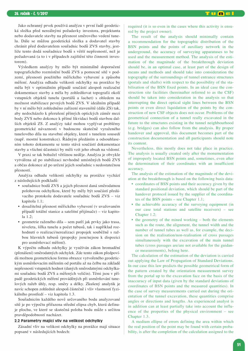


![Prednska 2 - Mechanismy pameti.ppt [režim kompatibility]memory.biomed.cas.cz/332/Learn Mem. 2011;18(2):108 ‐17. Nyní přejdeme od bezobratlých k savcům, především laboratorním](https://static.dokumenty.site/doc/80x56/60d0deb28ebaf60f8b58f7c3/prednska-2-mechanismy-reim-kompatibilitymemorybiomedcascz332-learn-mem.jpg)


