51
B35APO Architektura počítačů České vysoké učení technické, Fakulta elektrotechnická Architektury počítačů Ver.3.00 Predikce skoků + Hyper-Threading 1
B35APO Architektura počítačů
České vysoké učení technické, Fakulta elektrotechnická
Architektury počítačů
Ver.3.00
Predikce skoků + Hyper-Threading
1
Control Hazards
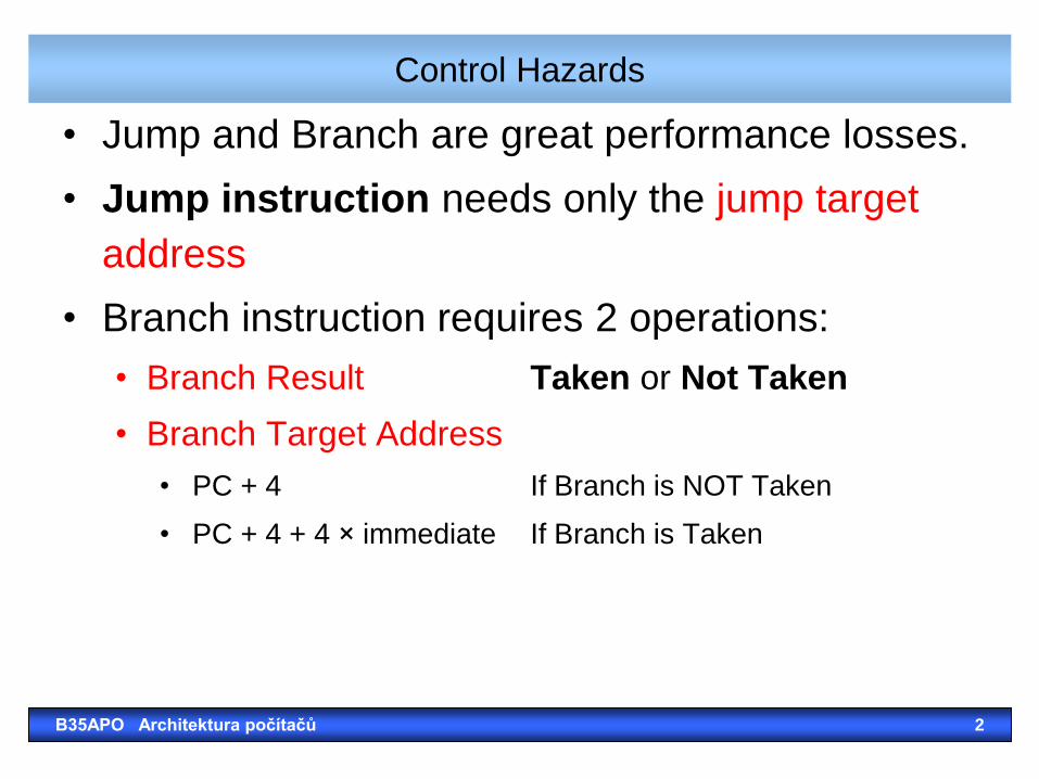
• Jump and Branch are great performance losses.
• Jump instruction needs only the jump target
address
• Branch instruction requires 2 operations:
• Branch Result Taken or Not Taken
• Branch Target Address
• PC + 4 If Branch is NOT Taken
• PC + 4 + 4 × immediate If Branch is Taken
B35APO Architektura počítačů 2
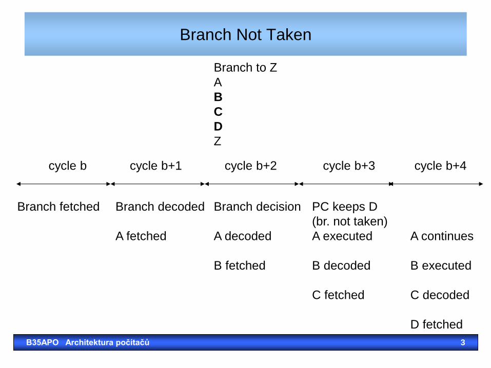
Branch Not Taken
Branch fetched Branch decoded Branch decision PC keeps D
(br. not taken)
A fetched A decoded A executed A continues
B fetched B decoded B executed
C fetched C decoded
D fetched
cycle b cycle b+1 cycle b+2 cycle b+3 cycle b+4
Branch to Z
A
B
C
D
Z
B35APO Architektura počítačů 3
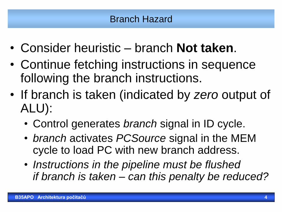
Branch Hazard
• Consider heuristic – branch Not taken.
• Continue fetching instructions in sequence following the branch instructions.
• If branch is taken (indicated by zero output of ALU):
• Control generates branch signal in ID cycle.
• branch activates PCSource signal in the MEM cycle to load PC with new branch address.
• Instructions in the pipeline must be flushed if branch is taken – can this penalty be reduced?
B35APO Architektura počítačů 4
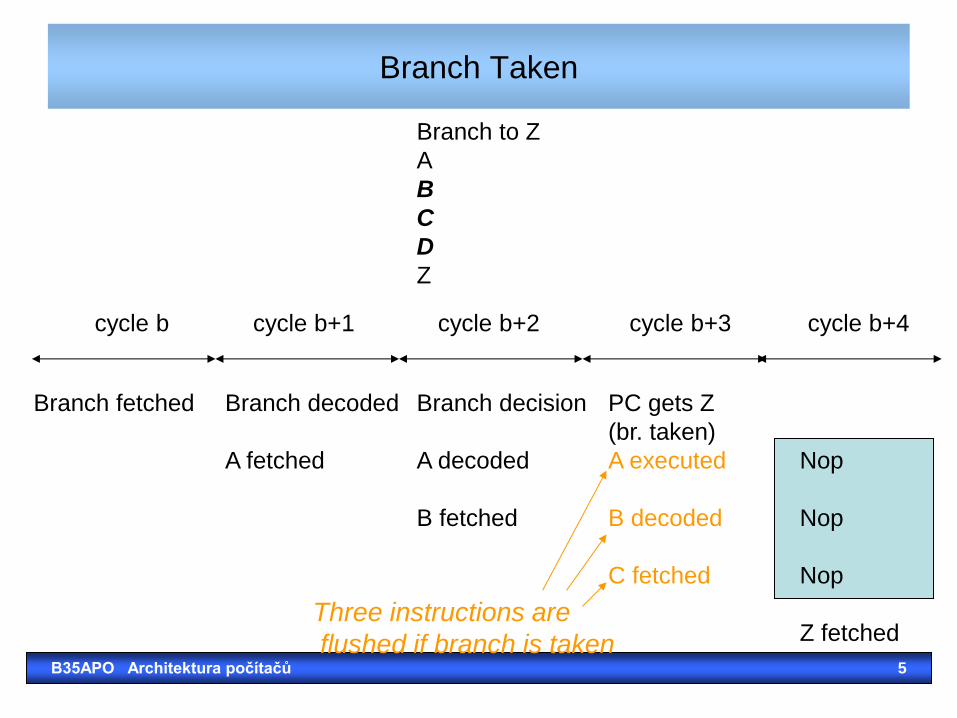
Branch Taken
Branch fetched Branch decoded Branch decision PC gets Z
(br. taken)
A fetched A decoded A executed Nop
B fetched B decoded Nop
C fetched Nop
Z fetched
cycle b cycle b+1 cycle b+2 cycle b+3 cycle b+4
Branch to Z
A
B
C
D
Z
Three instructions are
flushed if branch is taken B35APO Architektura počítačů 5
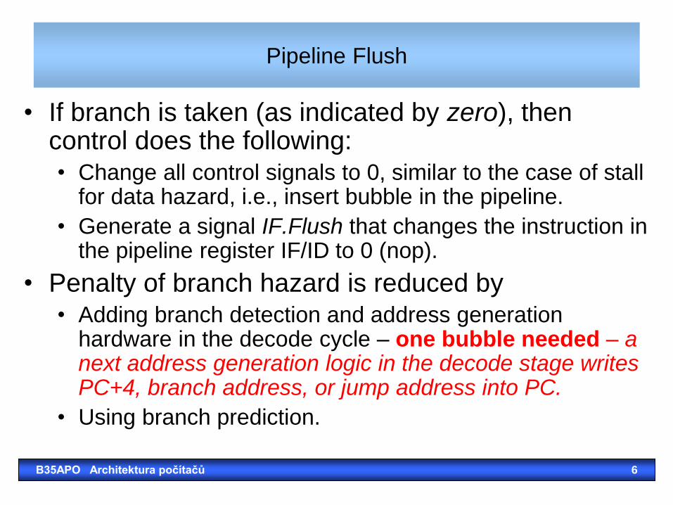
Pipeline Flush
• If branch is taken (as indicated by zero), then control does the following: • Change all control signals to 0, similar to the case of stall
for data hazard, i.e., insert bubble in the pipeline.
• Generate a signal IF.Flush that changes the instruction in the pipeline register IF/ID to 0 (nop).
• Penalty of branch hazard is reduced by • Adding branch detection and address generation
hardware in the decode cycle – one bubble needed – a next address generation logic in the decode stage writes PC+4, branch address, or jump address into PC.
• Using branch prediction.
B35APO Architektura počítačů 6
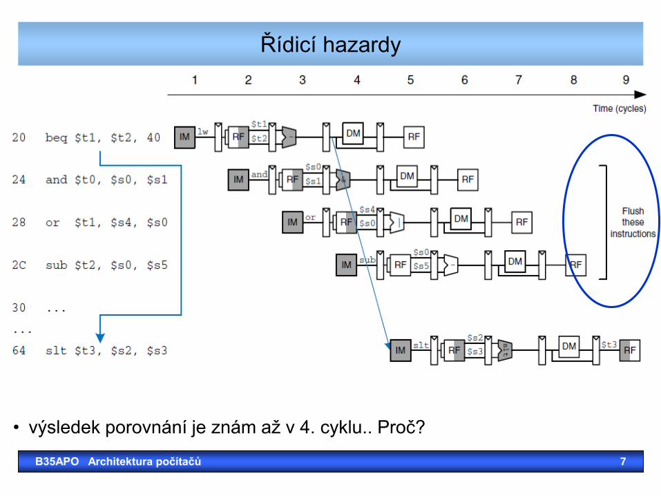
Řídicí hazardy
B35APO Architektura počítačů 7
• výsledek porovnání je znám až v 4. cyklu.. Proč?
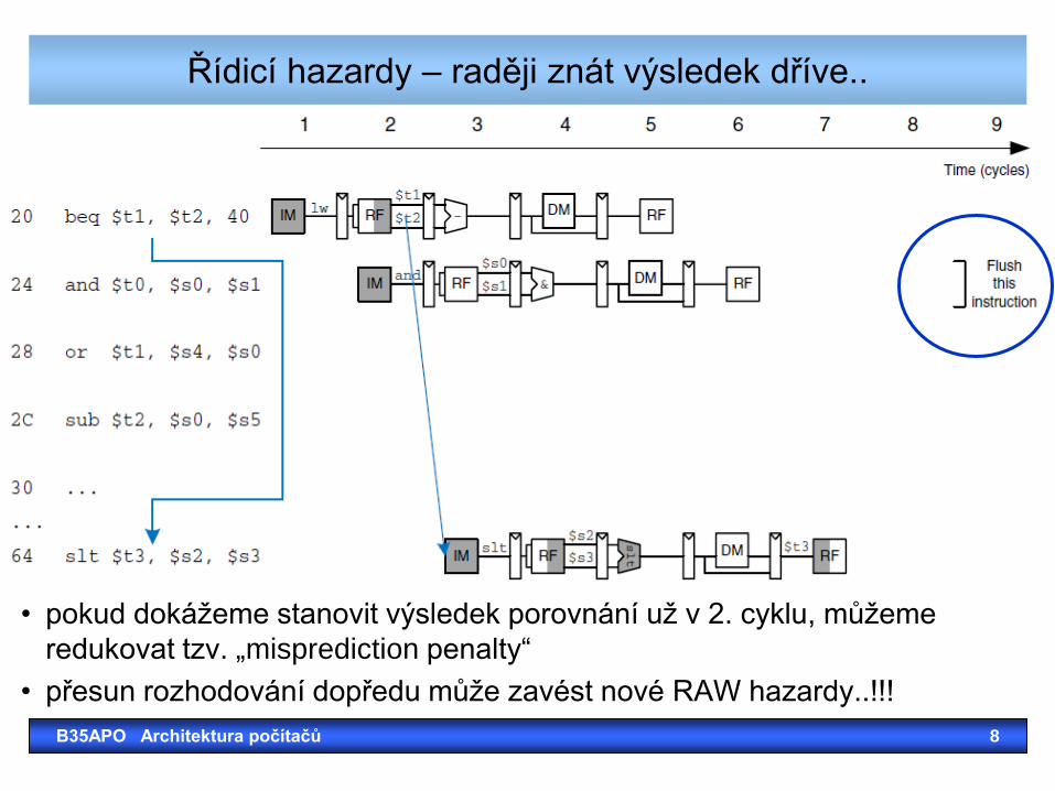
Řídicí hazardy – raději znát výsledek dříve..
B35APO Architektura počítačů 8
• pokud dokážeme stanovit výsledek porovnání už v 2. cyklu, můžeme
redukovat tzv. „misprediction penalty“
• přesun rozhodování dopředu může zavést nové RAW hazardy..!!!
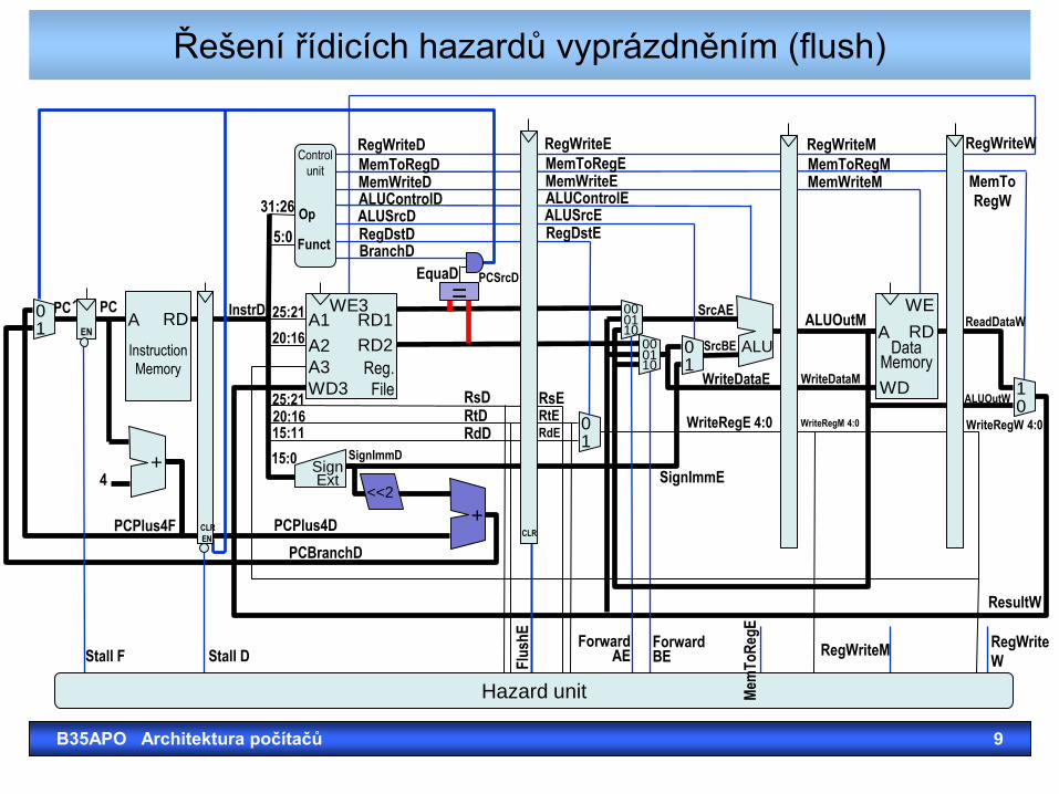
Řešení řídicích hazardů vyprázdněním (flush)
B35APO Architektura počítačů 9
0 1
Instruction
Memory
A RD
+
0 1
1 0
Data
Memory
A RD
WD
WE
<<2
=
Sign Ext
+
ALU 0 1
00
10 01
00 01 10
Control
unit
Hazard unit
RegWriteD
MemToRegD MemWriteD ALUControlD ALUSrcD RegDstD BranchD
RegWriteE
MemToRegE MemWriteE ALUControlE ALUSrcE RegDstE
RegWriteM
MemToRegM MemWriteM
RegWriteW
MemTo
RegW
EquaD PCSrcD
31:26
5:0
25:21
20:16
25:21 20:16 15:11
15:0 SignImmD
SignImmE
RsD RtD RdD
RsE RtE RdE
SrcAE
SrcBE
WriteDataE
WriteRegE 4:0
WriteDataM
ALUOutM
WriteRegM 4:0 WriteRegW 4:0
ALUOutW
ReadDataW
ResultW
PCPlus4D
PCBranchD
PCPlus4F
4
InstrD PC´ PC
EN CLR
EN
Op
Funct
Stall F Stall D
Flu
shE
Forward AE
Forward BE
Mem
To
Reg
E
RegWriteM RegWrite
W
Reg.
File
A1 RD1
A2 RD2
A3
WD3
WE3
CLR
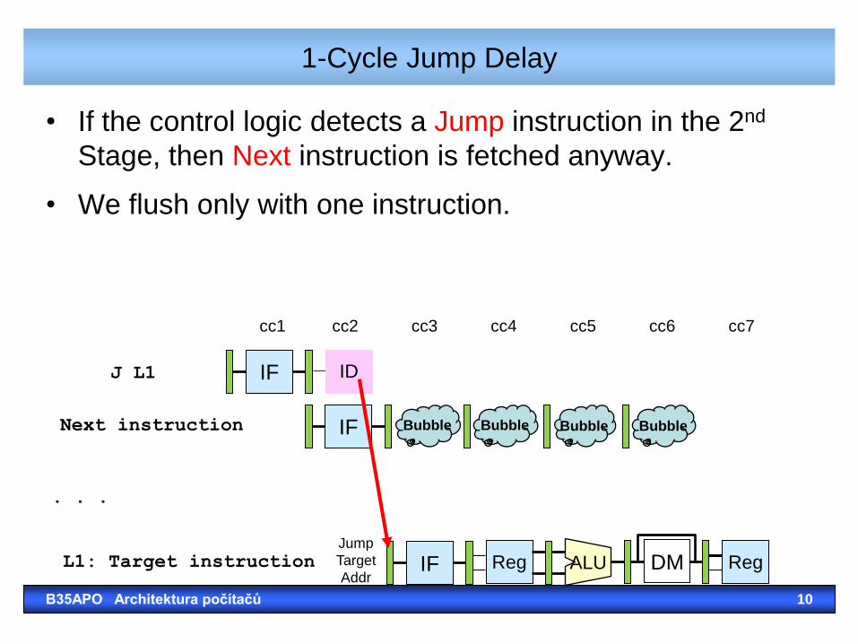
1-Cycle Jump Delay
• If the control logic detects a Jump instruction in the 2nd
Stage, then Next instruction is fetched anyway.
• We flush only with one instruction.
J L1 IF
cc1
Next instruction
. . .
L1: Target instruction
cc2
ID
IF
Jump
Target
Addr
cc4 cc5 cc6 cc7 cc3
Bubble Bubble Bubble Bubble
IF Reg DM ALU Reg
B35APO Architektura počítačů 10
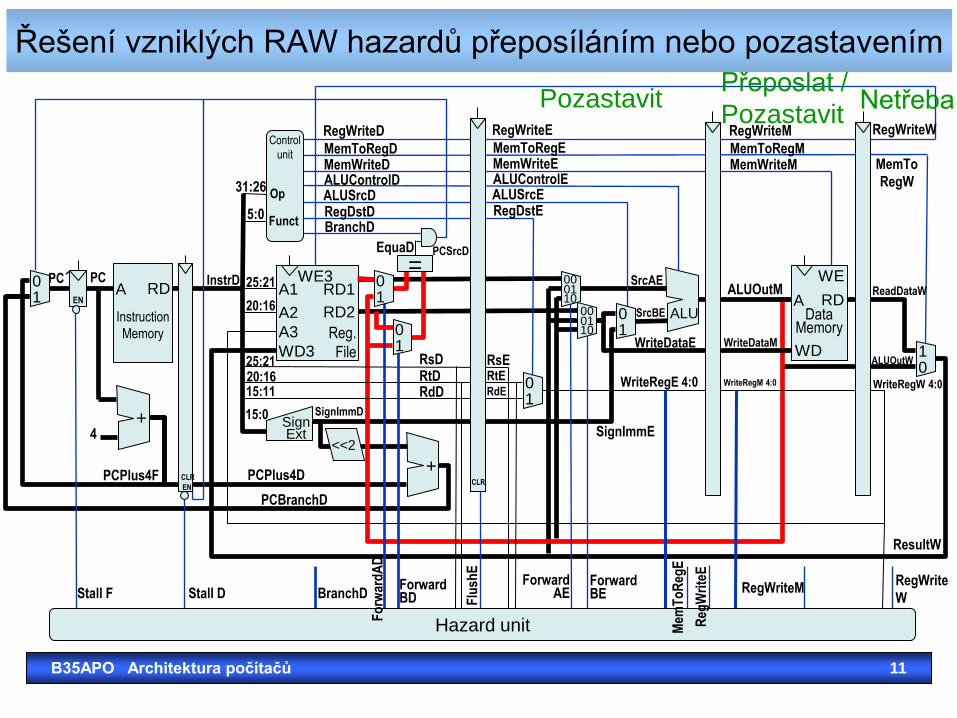
Řešení vzniklých RAW hazardů přeposíláním nebo pozastavením
B35APO Architektura počítačů 11
0 1
Instruction
Memory
A RD
+
0 1
1 0
Data
Memory
A RD
WD
WE
<<2
=
Sign Ext
+
ALU 0 1
00
10 01
00 01 10
0 1
0 1
Control
unit
Hazard unit
RegWriteD
MemToRegD MemWriteD ALUControlD ALUSrcD RegDstD BranchD
RegWriteE
MemToRegE MemWriteE ALUControlE ALUSrcE RegDstE
RegWriteM
MemToRegM MemWriteM
RegWriteW
MemTo
RegW
EquaD PCSrcD
31:26
5:0
25:21
20:16
25:21 20:16 15:11
15:0 SignImmD
SignImmE
RsD RtD RdD
RsE RtE RdE
SrcAE
SrcBE
WriteDataE
WriteRegE 4:0
WriteDataM
ALUOutM
WriteRegM 4:0 WriteRegW 4:0
ALUOutW
ReadDataW
ResultW
PCPlus4D
PCBranchD
PCPlus4F
4
InstrD PC´ PC
EN CLR
EN
Op
Funct
Stall F Stall D BranchD Forward BD
Fo
rwar
dA
D
Flu
shE
Forward AE
Forward BE
Mem
To
Reg
E
Reg
Wri
teE
RegWriteM RegWrite
W
Reg.
File
A1 RD1
A2 RD2
A3
WD3
WE3
CLR
Netřeba Přeposlat /
Pozastavit Pozastavit
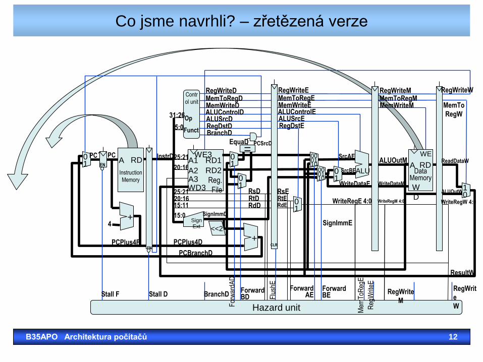
Co jsme navrhli? – zřetězená verze
B35APO Architektura počítačů 12
0 1
Instruction
Memory
A RD
+
0 1
1 0
Data
Memory
A RD
W
D
WE
<<2
=
Sign Ext
+
ALU 0 1
00
10 01
00 01 10
0 1
0 1
Contr
ol unit
Hazard unit
RegWriteD MemToRegD MemWriteD ALUControlD ALUSrcD RegDstD BranchD
RegWriteE MemToRegE MemWriteE ALUControlE ALUSrcE RegDstE
RegWriteM MemToRegM MemWriteM
RegWriteW
MemTo
RegW
EquaD PCSrcD
31:26
5:0
25:21
20:16
25:21 20:16 15:11
15:0 SignImmD
SignImmE
RsD RtD RdD
RsE RtE RdE
SrcAE
SrcBE
WriteDataE
WriteRegE 4:0
WriteDataM
ALUOutM
WriteRegM 4:0 WriteRegW 4:0
ALUOutW
ReadDataW
ResultW
PCPlus4D
PCBranchD
PCPlus4F
4
InstrD PC´ PC
EN CLR
EN
Op
Funct
Stall F Stall D BranchD Forward BD
For
war
dAD
Flu
shE
Forward AE
Forward BE
Mem
ToR
egE
Reg
Writ
eE
RegWrite
M
RegWrit
e
W
Reg.
File
A1 RD1
A2 RD2 A3 WD3
WE3
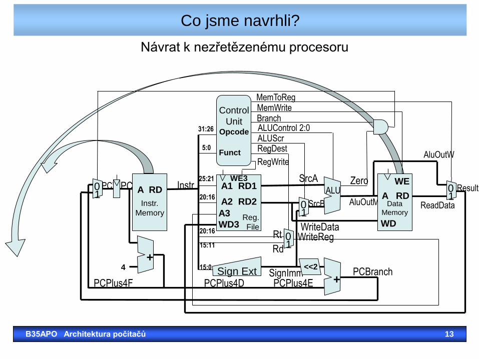
Co jsme navrhli?
B35APO Architektura počítačů 13
MemWrite MemToReg
Branch ALUControl 2:0 ALUScr RegDest
RegWrite
31:26
5:0
Control
Unit Opcode
Funct
4
PC’ PC Instr 25:21
20:16
20:16
15:11
15:0
SrcA
SrcB
Zero
AluOutM
WriteData WriteReg
SignImm PCPlus4D
PCBranch PCPlus4E
AluOutW
ReadData
Result
PCPlus4F
Rt
Rd
Instr.
Memory
A RD Data
Memory
A RD
WD
WE
Reg.
File
A1 RD1
A2 RD2
A3
WD3
WE3
+
+
0 1
0 1
0 1
0 1
Sign Ext <<2
ALU
Návrat k nezřetězenému procesoru
Data
Memory
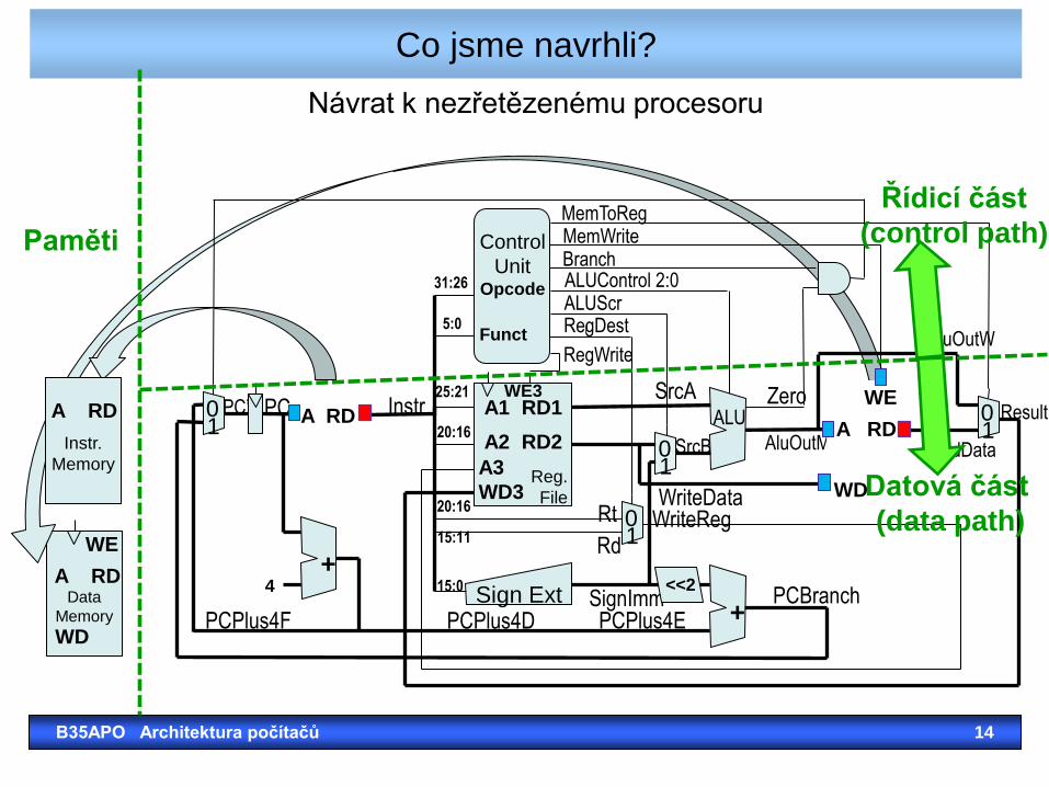
Co jsme navrhli?
B35APO Architektura počítačů 14
MemWrite MemToReg
Branch ALUControl 2:0 ALUScr RegDest
RegWrite
31:26
5:0
Control
Unit Opcode
Funct
4
PC’ PC Instr 25:21
20:16
20:16
15:11
15:0
SrcA
SrcB
Zero
AluOutM
WriteData WriteReg
SignImm PCPlus4D
PCBranch PCPlus4E
Result
PCPlus4F
Rt
Rd
A RD A RD
WD
WE
Reg.
File
A1 RD1
A2 RD2
A3
WD3
WE3
+
+
0 1
0 1
0 1
0 1
Sign Ext <<2
ALU
ReadData
AluOutW
Řídicí část
(control path)
Datová část
(data path)
Instr.
Memory
A RD
A RD
WD
WE
Návrat k nezřetězenému procesoru
Paměti
Data
Memory
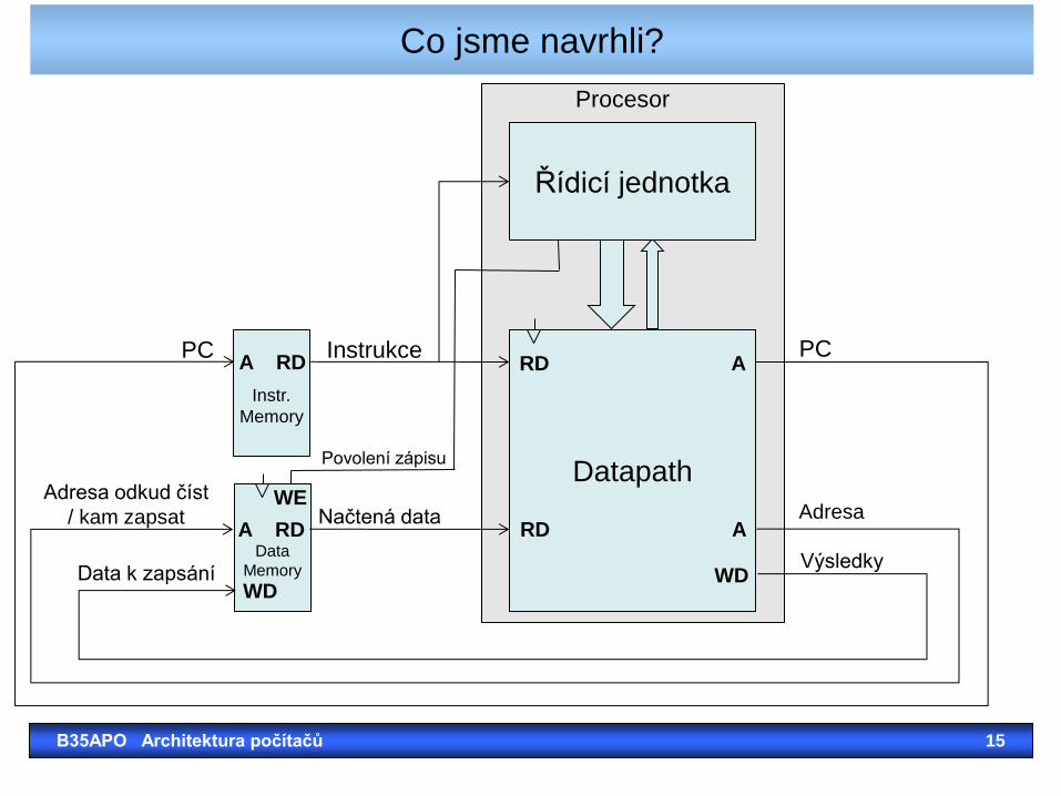
Co jsme navrhli?
B35APO Architektura počítačů 15
Instr.
Memory
A RD
A RD
WD
WE Datapath
Instrukce PC PC RD A
RD A
WD
Načtená data
Adresa odkud číst
/ kam zapsat
Data k zapsání
Povolení zápisu
Adresa
Výsledky
Procesor
Řídicí jednotka
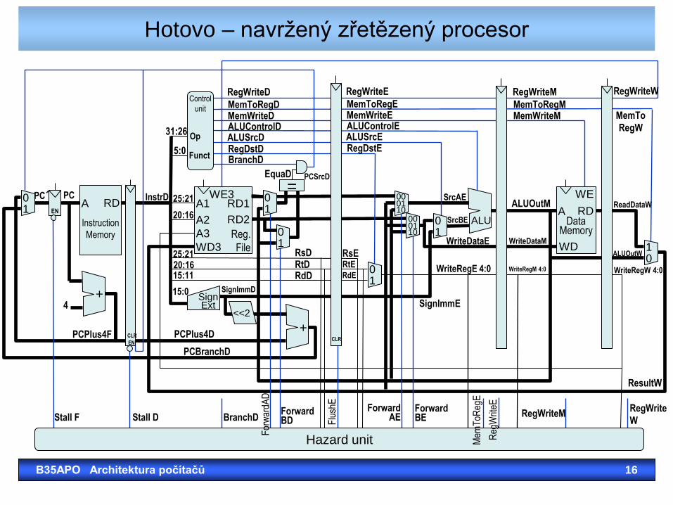
Hotovo – navržený zřetězený procesor
B35APO Architektura počítačů 16
0 1
Instruction
Memory
A RD
+
0 1
1 0
Data
Memory
A RD
WD
WE
<<2
=
Sign Ext
+
ALU 0 1
00
10 01
00 01 10
0 1
0 1
Control
unit
Hazard unit
RegWriteD
MemToRegD MemWriteD ALUControlD ALUSrcD RegDstD BranchD
RegWriteE
MemToRegE MemWriteE ALUControlE ALUSrcE RegDstE
RegWriteM
MemToRegM MemWriteM
RegWriteW
MemTo
RegW
EquaD PCSrcD
31:26
5:0
25:21
20:16
25:21 20:16 15:11
15:0 SignImmD
SignImmE
RsD RtD RdD
RsE RtE RdE
SrcAE
SrcBE
WriteDataE
WriteRegE 4:0
WriteDataM
ALUOutM
WriteRegM 4:0 WriteRegW 4:0
ALUOutW
ReadDataW
ResultW
PCPlus4D
PCBranchD
PCPlus4F
4
InstrD PC´ PC
EN CLR
EN
Op
Funct
Stall F Stall D BranchD Forward BD
For
war
dAD
Flu
shE
Forward AE
Forward BE
Mem
ToR
egE
Reg
Writ
eE
RegWriteM RegWrite
W
Reg.
File
A1 RD1
A2 RD2
A3
WD3
WE3
CLR
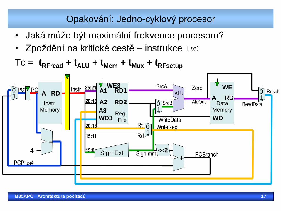
• Jaká může být maximální frekvence procesoru?
• Zpoždění na kritické cestě – instrukce lw:
Tc = tRFread + tALU + tMem + tMux + tRFsetup
Opakování: Jedno-cyklový procesor
B35APO Architektura počítačů 17
PC’ Result
SrcB
15:0
25:21 PC
4
Instr
20:16
20:16
15:11
SrcA Zero
AluOut
WriteData WriteReg
SignImm PCBranch
ReadData
PCPlus4
Rt
Rd
Instr.
Memory
A RD
Data
Memory
A RD
WD
WE
Reg.
File
A1 RD1
A2 RD2
A3
WD3
WE3
+
+
0 1
0 1
0 1
0 1
Sign Ext <<2
ALU
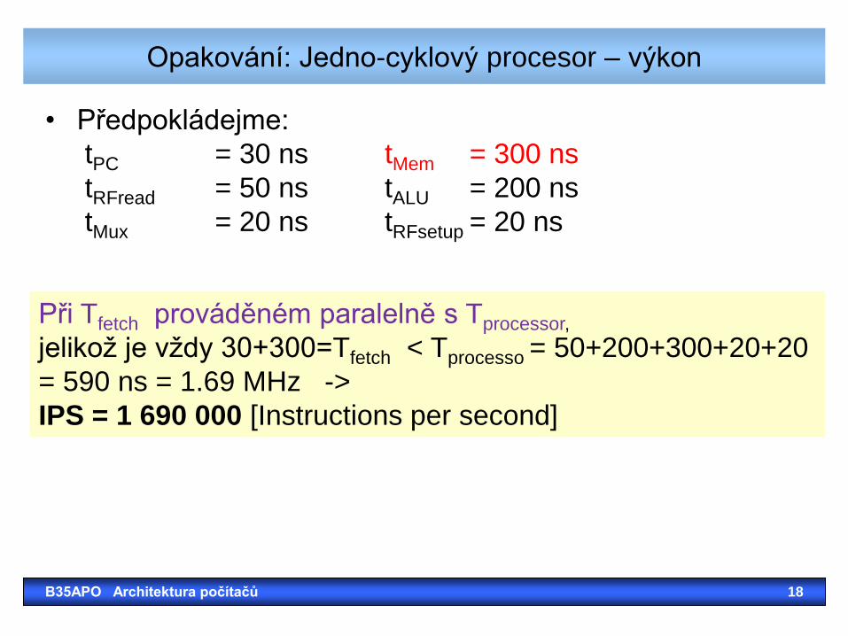
Opakování: Jedno-cyklový procesor – výkon
• Předpokládejme:
tPC = 30 ns tMem = 300 ns
tRFread = 50 ns tALU = 200 ns
tMux = 20 ns tRFsetup = 20 ns
B35APO Architektura počítačů 18
Při Tfetch prováděném paralelně s Tprocessor,
jelikož je vždy 30+300=Tfetch < Tprocesso = 50+200+300+20+20
= 590 ns = 1.69 MHz ->
IPS = 1 690 000 [Instructions per second]
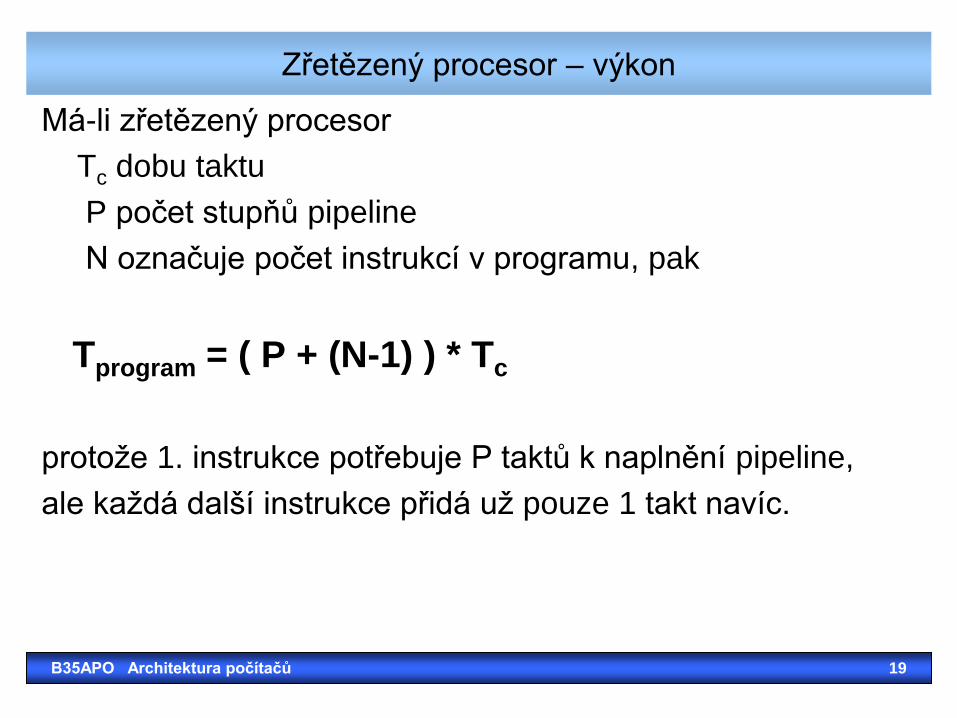
Má-li zřetězený procesor
Tc dobu taktu
P počet stupňů pipeline
N označuje počet instrukcí v programu, pak
Tprogram = ( P + (N-1) ) * Tc
protože 1. instrukce potřebuje P taktů k naplnění pipeline,
ale každá další instrukce přidá už pouze 1 takt navíc.
Zřetězený procesor – výkon
B35APO Architektura počítačů 19
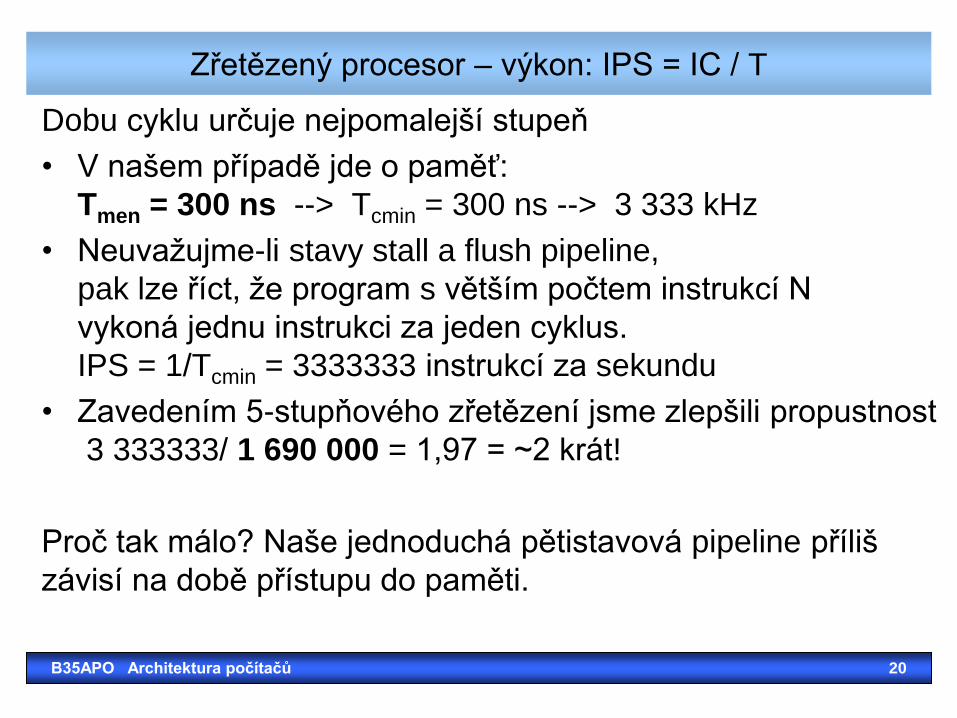
Dobu cyklu určuje nejpomalejší stupeň
• V našem případě jde o paměť:
Tmen = 300 ns --> Tcmin = 300 ns --> 3 333 kHz
• Neuvažujme-li stavy stall a flush pipeline,
pak lze říct, že program s větším počtem instrukcí N
vykoná jednu instrukci za jeden cyklus.
IPS = 1/Tcmin = 3333333 instrukcí za sekundu
• Zavedením 5-stupňového zřetězení jsme zlepšili propustnost
3 333333/ 1 690 000 = 1,97 = ~2 krát!
Proč tak málo? Naše jednoduchá pětistavová pipeline příliš
závisí na době přístupu do paměti.
Zřetězený procesor – výkon: IPS = IC / T
B35APO Architektura počítačů 20

B35APO Architektura počítačů 21
*
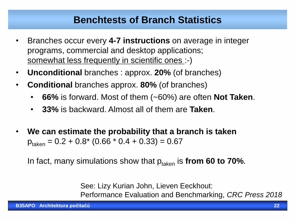
Benchtests of Branch Statistics
B35APO Architektura počítačů 22
• Branches occur every 4-7 instructions on average in integer
programs, commercial and desktop applications;
somewhat less frequently in scientific ones :-)
• Unconditional branches : approx. 20% (of branches)
• Conditional branches approx. 80% (of branches)
• 66% is forward. Most of them (~60%) are often Not Taken.
• 33% is backward. Almost all of them are Taken.
• We can estimate the probability that a branch is taken
ptaken = 0.2 + 0.8* (0.66 * 0.4 + 0.33) = 0.67
In fact, many simulations show that ptaken is from 60 to 70%.
See: Lizy Kurian John, Lieven Eeckhout:
Performance Evaluation and Benchmarking, CRC Press 2018
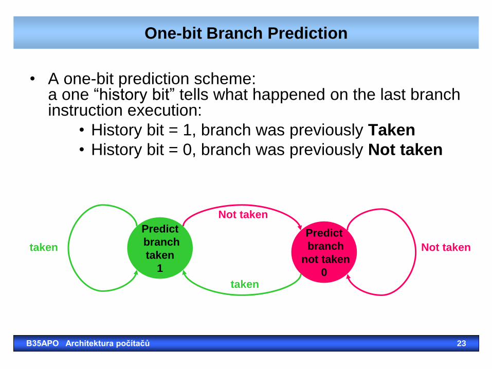
One-bit Branch Prediction
• A one-bit prediction scheme: a one “history bit” tells what happened on the last branch instruction execution:
• History bit = 1, branch was previously Taken
• History bit = 0, branch was previously Not taken
Predict
branch
not taken
0
Predict
branch
taken
1
taken
taken
Not taken
Not taken
B35APO Architektura počítačů 23
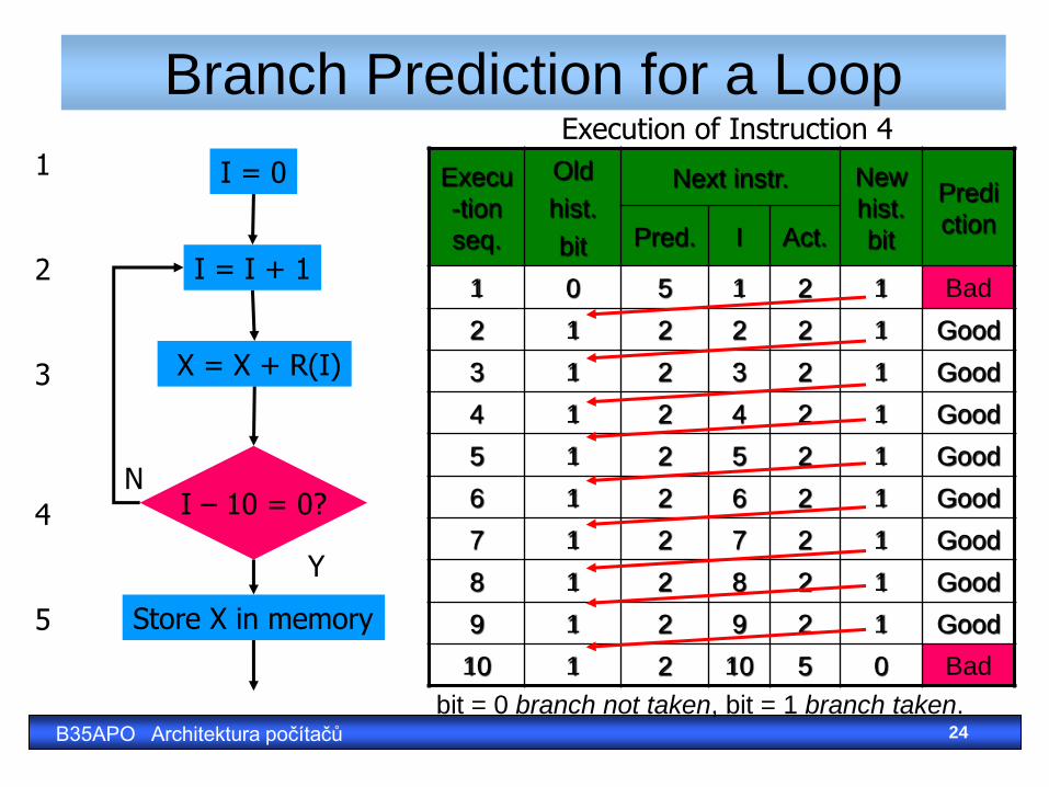
Branch Prediction for a Loop
I = 0
I = I + 1
I – 10 = 0?
Store X in memory
X = X + R(I)
Y
N
1 2 3 4 5
Execu
-tion
seq.
Old
hist.
bit
Next instr. New
hist.
bit
Predi
ction Pred. I Act.
1 0 5 1 2 1 Bad
2 1 2 2 2 1 Good
3 1 2 3 2 1 Good
4 1 2 4 2 1 Good
5 1 2 5 2 1 Good
6 1 2 6 2 1 Good
7 1 2 7 2 1 Good
8 1 2 8 2 1 Good
9 1 2 9 2 1 Good
10 1 2 10 5 0 Bad
Execution of Instruction 4
bit = 0 branch not taken, bit = 1 branch taken. B35APO Architektura počítačů 24
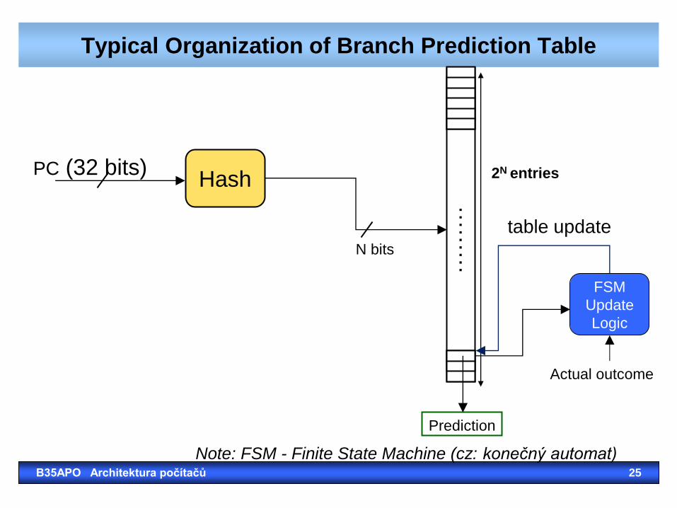
Typical Organization of Branch Prediction Table
Hash PC (32 bits) 2N entries
Prediction
N bits
FSM
Update
Logic
table update
Actual outcome
……
…
Note: FSM - Finite State Machine (cz: konečný automat) B35APO Architektura počítačů 25
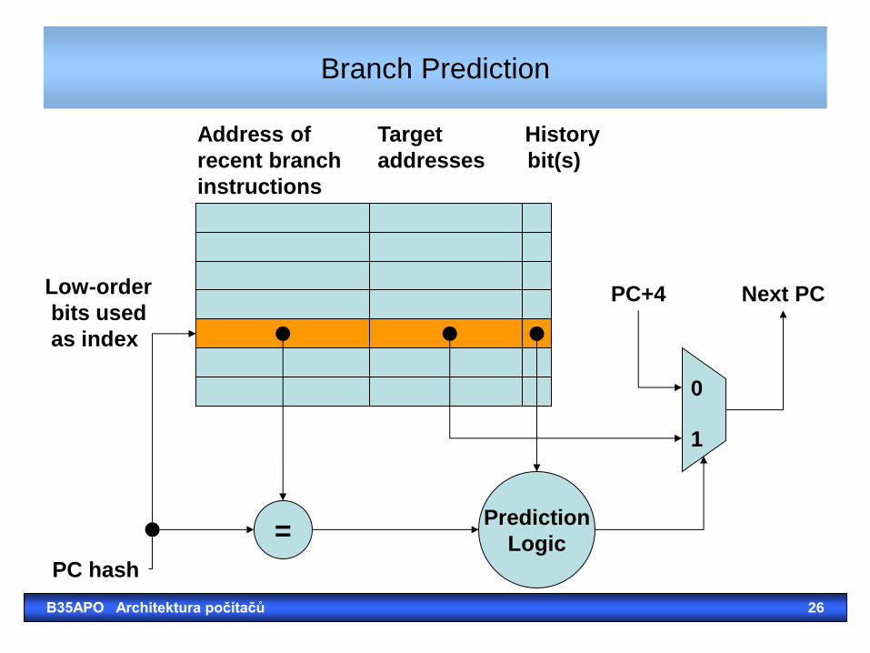
Branch Prediction
= Prediction
Logic
0
1
PC+4 Next PC
PC hash
Low-order
bits used
as index
Address of Target History
recent branch addresses bit(s)
instructions
B35APO Architektura počítačů 26
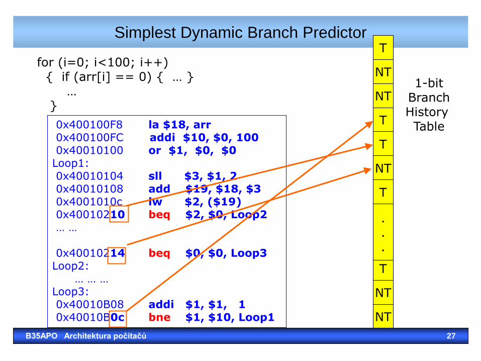
for (i=0; i<100; i++) { if (arr[i] == 0) { … } … }
Simplest Dynamic Branch Predictor
T
NT
T
T
NT
NT
.
.
.
0x400100F8 la $18, arr 0x400100FC addi $10, $0, 100 0x40010100 or $1, $0, $0 Loop1: 0x40010104 sll $3, $1, 2 0x40010108 add $19, $18, $3 0x4001010c lw $2, ($19) 0x40010210 beq $2, $0, Loop2 … … 0x40010214 beq $0, $0, Loop3 Loop2: … … … Loop3: 0x40010B08 addi $1, $1, 1 0x40010B0c bne $1, $10, Loop1
NT
T
1-bit Branch History Table
T
NT
B35APO Architektura počítačů 27
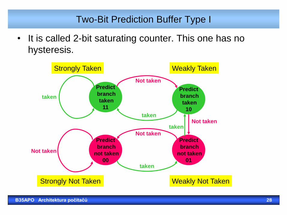
Two-Bit Prediction Buffer Type I
• It is called 2-bit saturating counter. This one has no
hysteresis.
Predict
branch
not taken
00
Predict
branch
taken
10
Predict
branch
taken
11
Predict
branch
not taken
01
taken
taken
taken
taken
Not taken
Not taken
Not taken
Not taken
Weakly Not Taken
Strongly Taken Weakly Taken
Strongly Not Taken
B35APO Architektura počítačů 28
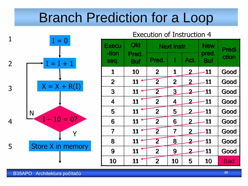
Branch Prediction for a Loop
I = 0
I = I + 1
I – 10 = 0?
Store X in memory
X = X + R(I)
Y
N
1 2 3 4 5
Execu
-tion
seq.
Old
Pred.
Buf
Next instr. New
pred.
Buf
Predi
ction Pred. I Act.
1 10 2 1 2 11 Good
2 11 2 2 2 11 Good
3 11 2 3 2 11 Good
4 11 2 4 2 11 Good
5 11 2 5 2 11 Good
6 11 2 6 2 11 Good
7 11 2 7 2 11 Good
8 11 2 8 2 11 Good
9 11 2 9 2 11 Good
10 11 2 10 5 10 Bad
Execution of Instruction 4
B35APO Architektura počítačů 29
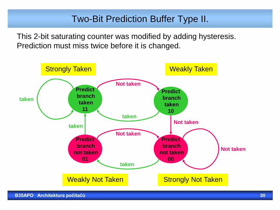
Two-Bit Prediction Buffer Type II.
This 2-bit saturating counter was modified by adding hysteresis.
Prediction must miss twice before it is changed.
Weakly Not Taken
Predict
branch
not taken
01
Predict
branch
taken
10
Predict
branch
taken
11
Predict
branch
not taken
00
taken
taken
taken
taken
Not taken
Not taken
Not taken
Not taken
Strongly Taken Weakly Taken
Strongly Not Taken
B35APO Architektura počítačů 30
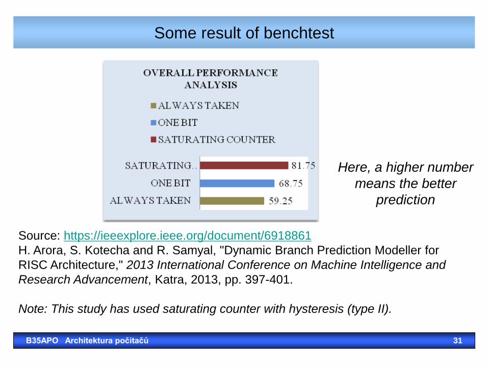
Some result of benchtest
B35APO Architektura počítačů 31
Source: https://ieeexplore.ieee.org/document/6918861
H. Arora, S. Kotecha and R. Samyal, "Dynamic Branch Prediction Modeller for
RISC Architecture," 2013 International Conference on Machine Intelligence and
Research Advancement, Katra, 2013, pp. 397-401.
Note: This study has used saturating counter with hysteresis (type II).
Here, a higher number
means the better
prediction
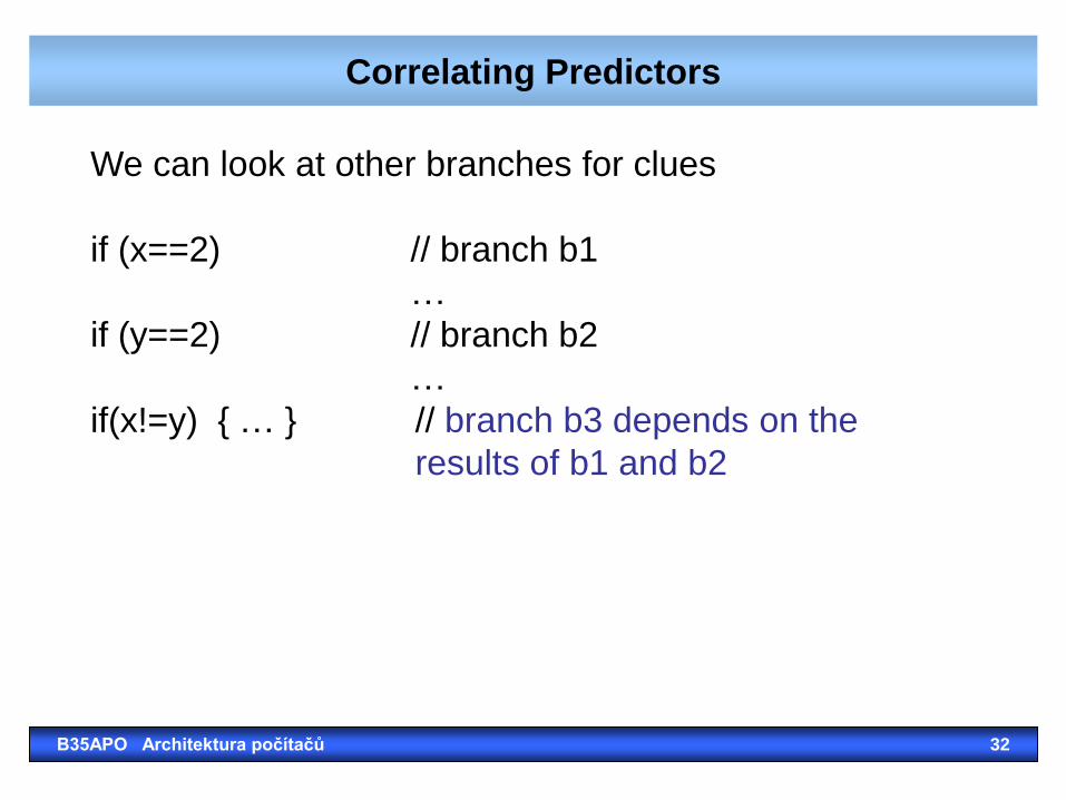
Correlating Predictors
B35APO Architektura počítačů 32
We can look at other branches for clues
if (x==2) // branch b1
…
if (y==2) // branch b2
…
if(x!=y) { … } // branch b3 depends on the
results of b1 and b2
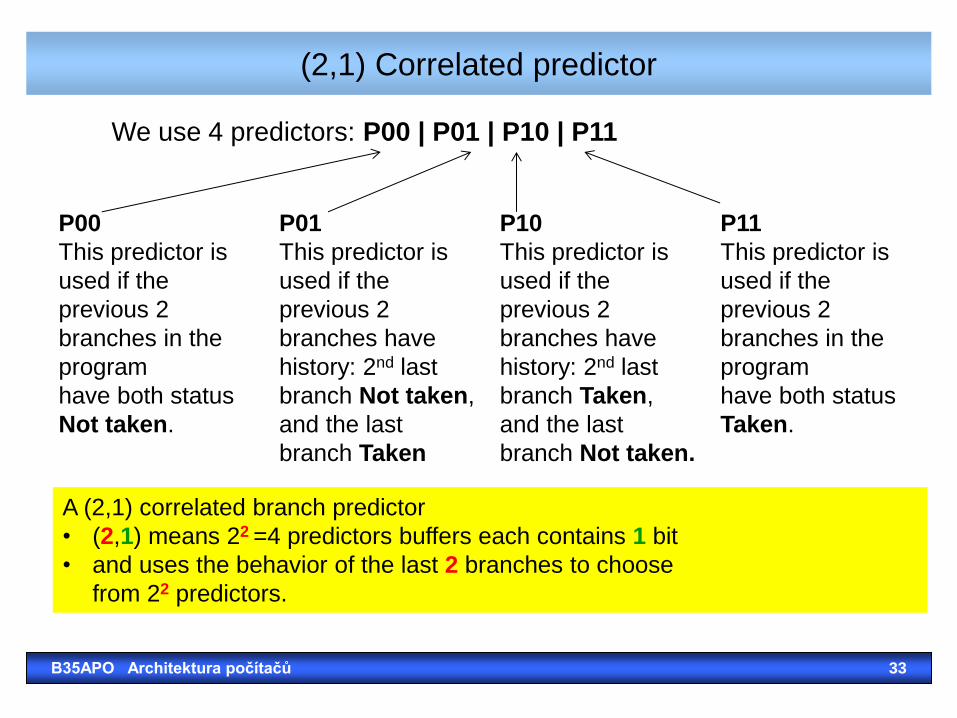
(2,1) Correlated predictor
B35APO Architektura počítačů 33
P00
This predictor is
used if the
previous 2
branches in the
program
have both status
Not taken.
P01
This predictor is
used if the
previous 2
branches have
history: 2nd last
branch Not taken,
and the last
branch Taken
P10
This predictor is
used if the
previous 2
branches have
history: 2nd last
branch Taken,
and the last
branch Not taken.
P11
This predictor is
used if the
previous 2
branches in the
program
have both status
Taken.
P00 | P01 | P10 | P11
A (2,1) correlated branch predictor
• (2,1) means 22 =4 predictors buffers each contains 1 bit
• and uses the behavior of the last 2 branches to choose
from 22 predictors.
We use 4 predictors:
Correlating Predictors
B35APO Architektura počítačů 34
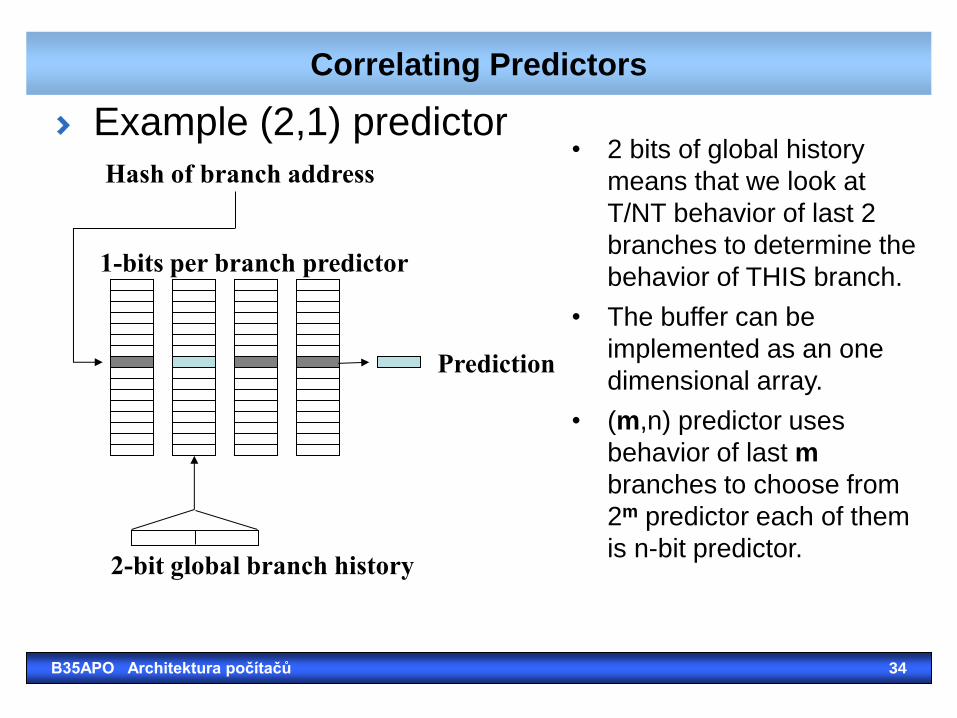
Example (2,1) predictor
Hash of branch address
1-bits per branch predictor
Prediction
2-bit global branch history
• 2 bits of global history
means that we look at
T/NT behavior of last 2
branches to determine the
behavior of THIS branch.
• The buffer can be
implemented as an one
dimensional array.
• (m,n) predictor uses
behavior of last m
branches to choose from
2m predictor each of them
is n-bit predictor.
Correlating Predictors in SPEC89
B35APO Architektura počítačů 35
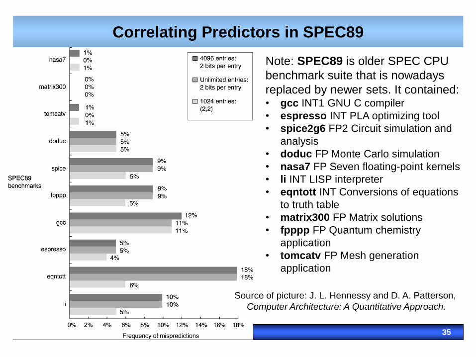
Note: SPEC89 is older SPEC CPU
benchmark suite that is nowadays
replaced by newer sets. It contained: • gcc INT1 GNU C compiler
• espresso INT PLA optimizing tool
• spice2g6 FP2 Circuit simulation and
analysis
• doduc FP Monte Carlo simulation
• nasa7 FP Seven floating-point kernels
• li INT LISP interpreter
• eqntott INT Conversions of equations
to truth table
• matrix300 FP Matrix solutions
• fpppp FP Quantum chemistry
application
• tomcatv FP Mesh generation
application
Source of picture: J. L. Hennessy and D. A. Patterson,
Computer Architecture: A Quantitative Approach.
Tournament Predictors
• Motivation for correlating branch predictors is
2-bit predictor failed on important branches; by adding
global information, performance was improved.
• Tournament predictors: use 2 predictors, 1 based on
global information and 1 based on local information
(local branch was taken, not taken), and combine them
with a selector.
• They use n-bit saturating counter to choose between
predictors.
• Hopes to select right predictor for right branch.
B35APO Architektura počítačů 36
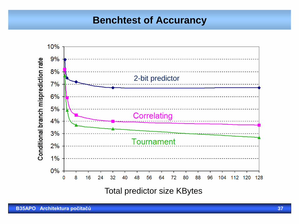
Benchtest of Accurancy
B35APO Architektura počítačů 37
Total predictor size KBytes
2-bit predictor

B35APO Architektura počítačů 38
*
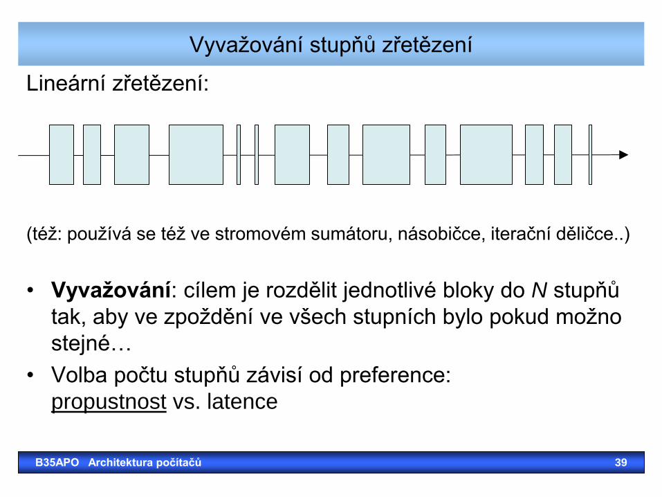
Vyvažování stupňů zřetězení
Lineární zřetězení:
(též: používá se též ve stromovém sumátoru, násobičce, iterační děličce..)
• Vyvažování: cílem je rozdělit jednotlivé bloky do N stupňů
tak, aby ve zpoždění ve všech stupních bylo pokud možno
stejné…
• Volba počtu stupňů závisí od preference:
propustnost vs. latence
B35APO Architektura počítačů 39
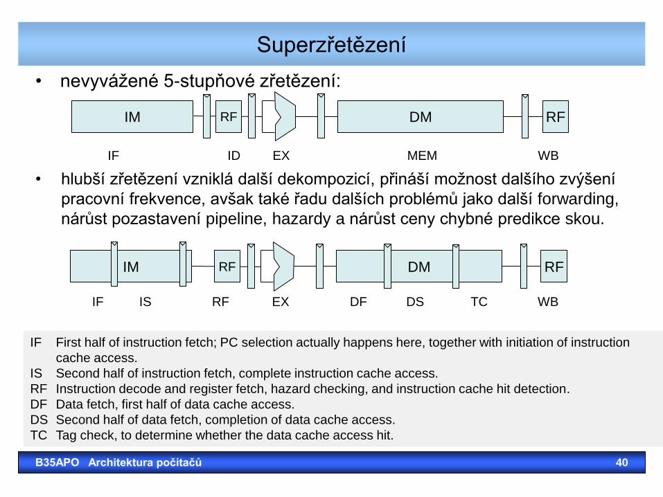
Superzřetězení
• nevyvážené 5-stupňové zřetězení:
B35APO Architektura počítačů 40
DM RF IM RF
DM RF IM RF
IF First half of instruction fetch; PC selection actually happens here, together with initiation of instruction
cache access.
IS Second half of instruction fetch, complete instruction cache access.
RF Instruction decode and register fetch, hazard checking, and instruction cache hit detection.
DF Data fetch, first half of data cache access.
DS Second half of data fetch, completion of data cache access.
TC Tag check, to determine whether the data cache access hit.
IF ID EX MEM WB
• hlubší zřetězení vzniklá další dekompozicí, přináší možnost dalšího zvýšení
pracovní frekvence, avšak také řadu dalších problémů jako další forwarding,
nárůst pozastavení pipeline, hazardy a nárůst ceny chybné predikce skou.
IF IS RF EX DF DS TC WB
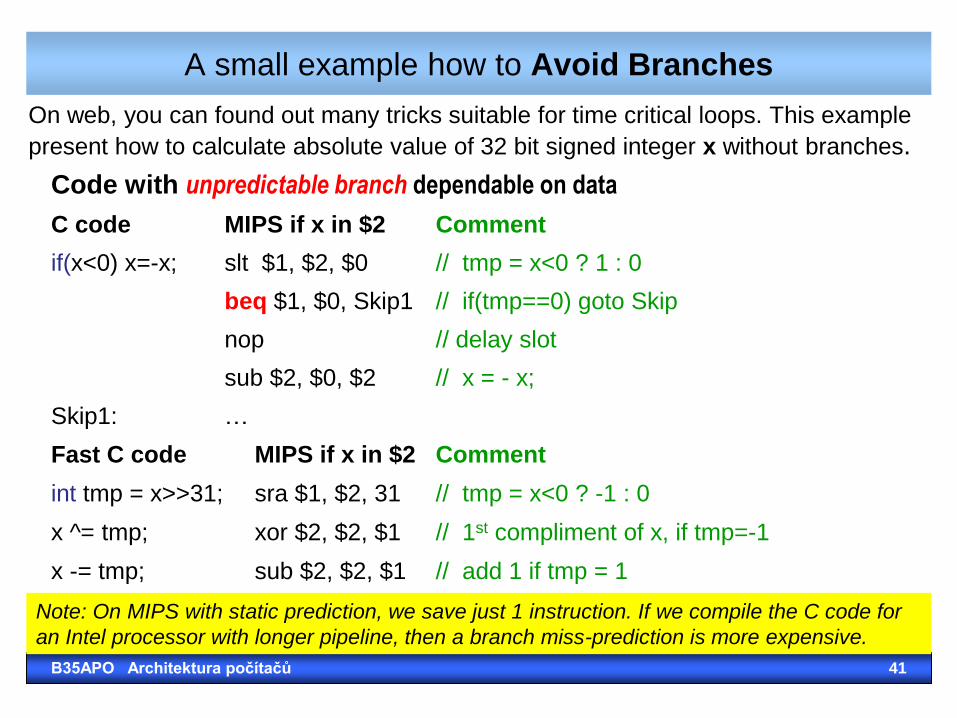
A small example how to Avoid Branches
On web, you can found out many tricks suitable for time critical loops. This example
present how to calculate absolute value of 32 bit signed integer x without branches.
B35APO Architektura počítačů 41
Fast C code MIPS if x in $2 Comment
int tmp = x>>31; sra $1, $2, 31 // tmp = x<0 ? -1 : 0
x ^= tmp; xor $2, $2, $1 // 1st compliment of x, if tmp=-1
x -= tmp; sub $2, $2, $1 // add 1 if tmp = 1
Code with unpredictable branch dependable on data
C code MIPS if x in $2 Comment
if(x<0) x=-x; slt $1, $2, $0 // tmp = x<0 ? 1 : 0
beq $1, $0, Skip1 // if(tmp==0) goto Skip
nop // delay slot
sub $2, $0, $2 // x = - x;
Skip1: …
Note: On MIPS with static prediction, we save just 1 instruction. If we compile the C code for
an Intel processor with longer pipeline, then a branch miss-prediction is more expensive.
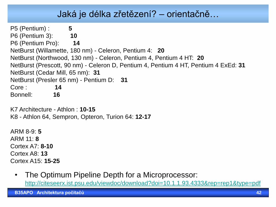
Jaká je délka zřetězení? – orientačně…
• The Optimum Pipeline Depth for a Microprocessor: http://citeseerx.ist.psu.edu/viewdoc/download?doi=10.1.1.93.4333&rep=rep1&type=pdf
B35APO Architektura počítačů 42
P5 (Pentium) : 5
P6 (Pentium 3): 10
P6 (Pentium Pro): 14
NetBurst (Willamette, 180 nm) - Celeron, Pentium 4: 20
NetBurst (Northwood, 130 nm) - Celeron, Pentium 4, Pentium 4 HT: 20
NetBurst (Prescott, 90 nm) - Celeron D, Pentium 4, Pentium 4 HT, Pentium 4 ExEd: 31
NetBurst (Cedar Mill, 65 nm): 31
NetBurst (Presler 65 nm) - Pentium D: 31
Core : 14
Bonnell: 16
K7 Architecture - Athlon : 10-15
K8 - Athlon 64, Sempron, Opteron, Turion 64: 12-17
ARM 8-9: 5
ARM 11: 8
Cortex A7: 8-10
Cortex A8: 13
Cortex A15: 15-25

B35APO Architektura počítačů 43
Definition
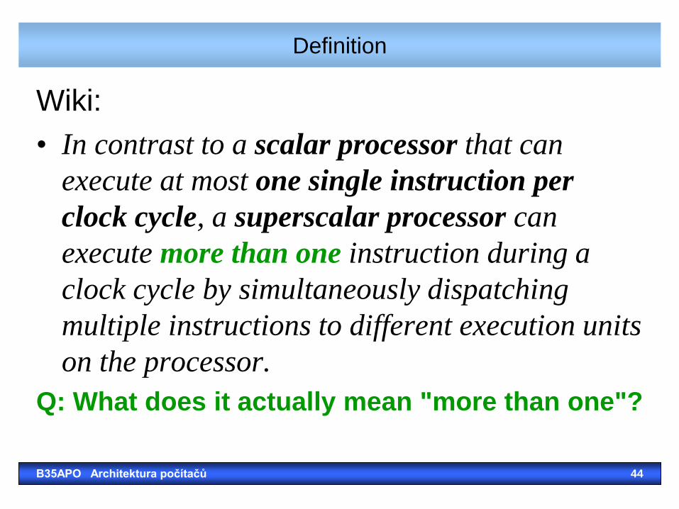
Wiki:
• In contrast to a scalar processor that can
execute at most one single instruction per
clock cycle, a superscalar processor can
execute more than one instruction during a
clock cycle by simultaneously dispatching
multiple instructions to different execution units
on the processor.
Q: What does it actually mean "more than one"?
B35APO Architektura počítačů 44
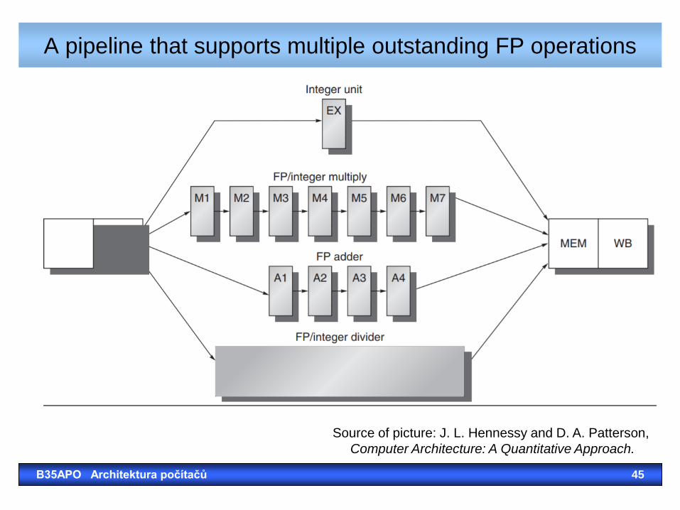
A pipeline that supports multiple outstanding FP operations
B35APO Architektura počítačů 45
Source of picture: J. L. Hennessy and D. A. Patterson,
Computer Architecture: A Quantitative Approach.
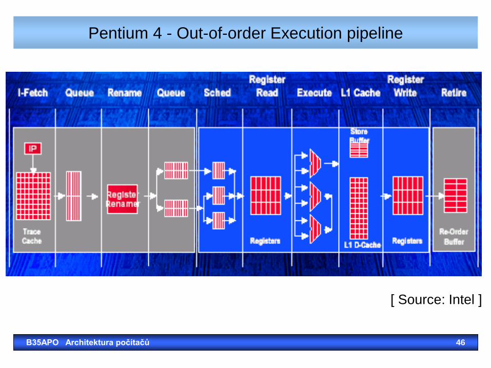
Pentium 4 - Out-of-order Execution pipeline
B35APO Architektura počítačů 46
[ Source: Intel ]
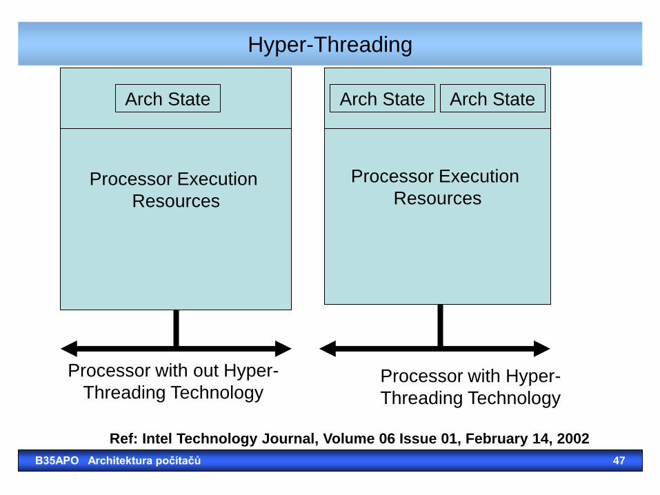
Hyper-Threading
B35APO Architektura počítačů 47
Processor Execution
Resources
Processor Execution
Resources
Arch State Arch State Arch State
Processor with out Hyper-
Threading Technology Processor with Hyper-
Threading Technology
Ref: Intel Technology Journal, Volume 06 Issue 01, February 14, 2002
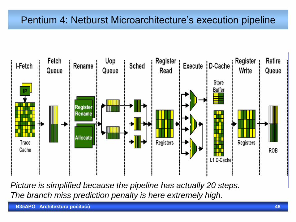
Pentium 4: Netburst Microarchitecture’s execution pipeline
B35APO Architektura počítačů 48
Picture is simplified because the pipeline has actually 20 steps.
The branch miss prediction penalty is here extremely high.
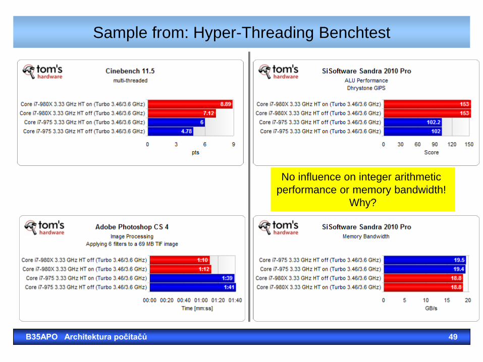
Sample from: Hyper-Threading Benchtest
B35APO Architektura počítačů 49
No influence on integer arithmetic
performance or memory bandwidth!
Why?
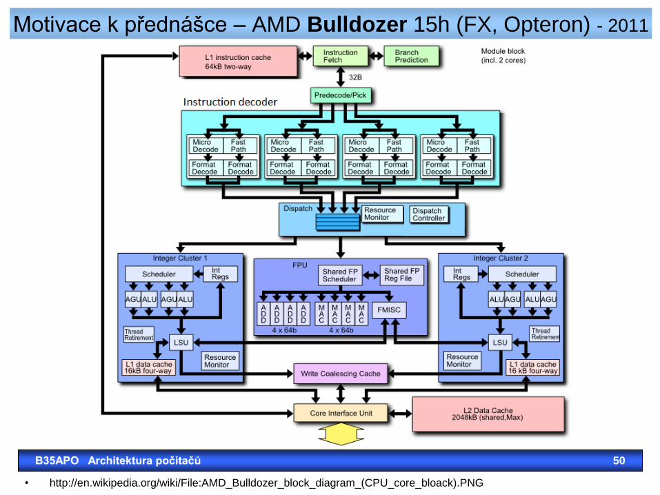
Motivace k přednášce – AMD Bulldozer 15h (FX, Opteron) - 2011
• http://en.wikipedia.org/wiki/File:AMD_Bulldozer_block_diagram_(CPU_core_bloack).PNG
B35APO Architektura počítačů 50
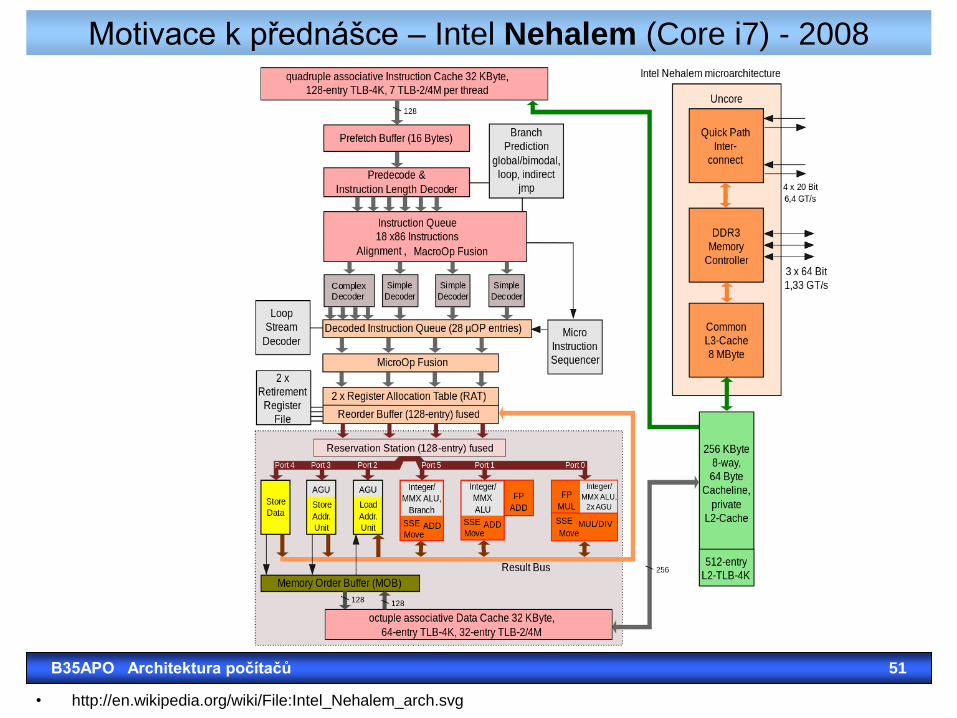
Motivace k přednášce – Intel Nehalem (Core i7) - 2008
• http://en.wikipedia.org/wiki/File:Intel_Nehalem_arch.svg
B35APO Architektura počítačů 51


