STATUS OF NESTOR FACILITY V. Androsov, I. Drebot, A. Gordienko, V. Grevtsev, A. Gvozd, V. Ivashchenko, I.I. Karnaukhov, I.M. Karnaukhov, V. Kozin, V. Lyashchenko, N. Mocheshnikov, V. Margin, A. Mytsykov, I. Neklyudov, F. Peev, A. Reuzayev, A. Shcherbakov, S. Sheyko, V. Skirda, Y. Telegin, V. Trotsenko, N. Varavin, A. Zelinsky, O. Zvonaryova, NSC KIPT, Kharkov, Ukraine J.I.M. Botman, Eindhoven University of Technology, Netherlands Abstract The status of X-ray generator NESTOR that is under construction in Kharkov Institute of Physics and Technology is described in the paper. INTRODUCTION The new Kharkov accelerator facility NESTOR (New Electron STOrage Ring) [1,2] is going to generate intense X-rays trough Compton back scattering. The facility consists of the compact 40-225 MeV storage ring, linear 35-90 MeV electron accelerator as an injector, transportation system, Nd:Yag laser system and optical cavity. It is expected that the facility will generate X-rays flux of about 10 13 phot/s. NESTOR facility commissioning should be begun this autumn. The latest NESTOR team activity is directed to the following: • magnetic element characteristic measurements and development of fiducialization procedures; • design and development of survey and alignment system; • development of the facility vacuum system; • RF system assembling and commissioning. In the paper the resent results on activity directions mentioned above are briefly described. MAGNETIC SYSTEM To the purpose of NESTOR facility magnetic element quality testing a Hall probe array with 7 probes was designed. It serves to determine magnetic field distribution along a line of Hall probe installation. The Hall probe array is assembled at a cooper plate basement of 40х60 mm size. At the surface of the basement there is thermo stabilization pipe (see Fig. 1). Hall probes are installed in a groove. Height adjusters 8 (see Fig.1) are supports that are installed at the plate surface in parallel to the plane of magnetic field measurements. For regular operation the Hall probe array will be covered by thermo isolator. A magnetic field B in a point of a Hall probe position is: ( ) 0 ( ) E T kTE B G G = + , where E 0 (T) is probe fixed term or “zero” reading, G is probe sensitivity, E is a measured Hall probe voltage, k(T) is correcting temperature coefficient. Therefore, to determine a magnetic field we should know E 0 (T) “zero” reading for each probe, temperature dependence of a probe voltage and each probe sensitivity. Figure 1: Hall probe array. 1-7 Hall probes; 8 – height adjusters; 9- thermo stabilization pipes Since a Hall probe senses only normal component of the field we can determine the “zero” reading of the Hall probe E 0 by measuring field in a scattered field under different angles of the Hall probe array orientation. For this purpose we moved the array as far as 0.5 m from the possible sources of a magnetic field. Measurements were carried out by rotating the array around the arbitrary axis (3 directions) with 45° steps. Measurement data were approximated by periodic harmonic function with fixed term. The measurements were carried out for each probe and for two different probe temperatures 13°C and 38°C. As a result “zero” reading fixed terms were taken. To determine the correcting temperature coefficient k(T) of each Hall probe the measurements of each probe signal in a uniform stationary magnetic field were carried out. The value of the field was controlled with a NMR probe. The measurements were carried out in temperature range 13-38°C in the magnetic field equal to 0.215 Т. Signals of each probe were normalized on probe signal at temperature equal to 35.4°C. As a result, we will use correcting linear function that based on these experimental data. To determine the Hall probe array sensitivity G we put the Hall probe and the NMR probe to homogeneous field area of a dipole magnet with poles 130×140 mm size. The Hall probes were calibrated in the field of 0.2-0.4 T with different polarity of the field. Temperature was kept as 34.5°C±0.3°C. The results can be used at Hall current equal to 75 mA Measurements accuracy is not worse then 1.5*10 -3 , and relative accuracy is 10 -4 . As a result, to determine a value of a magnetic field we will use data of Table 1. . WEPEA063 Proceedings of IPAC’10, Kyoto, Japan 2630 02 Synchrotron Light Sources and FELs A05 Synchrotron Radiation Facilities
Transcript
STATUS OF NESTOR FACILITY
V. Androsov, I. Drebot, A. Gordienko, V. Grevtsev, A. Gvozd, V. Ivashchenko, I.I. Karnaukhov, I.M. Karnaukhov, V. Kozin, V. Lyashchenko, N. Mocheshnikov, V. Margin, A. Mytsykov,
I. Neklyudov, F. Peev, A. Reuzayev, A. Shcherbakov, S. Sheyko, V. Skirda, Y. Telegin, V. Trotsenko, N. Varavin, A. Zelinsky, O. Zvonaryova, NSC KIPT, Kharkov, Ukraine
J.I.M. Botman, Eindhoven University of Technology, Netherlands
Abstract The status of X-ray generator NESTOR that is under
construction in Kharkov Institute of Physics and Technology is described in the paper.
INTRODUCTION The new Kharkov accelerator facility NESTOR (New
Electron STOrage Ring) [1,2] is going to generate intense X-rays trough Compton back scattering. The facility consists of the compact 40-225 MeV storage ring, linear 35-90 MeV electron accelerator as an injector, transportation system, Nd:Yag laser system and optical cavity. It is expected that the facility will generate X-rays flux of about 1013 phot/s. NESTOR facility commissioning should be begun this autumn.
The latest NESTOR team activity is directed to the following: • magnetic element characteristic measurements and development of fiducialization procedures; • design and development of survey and alignment system; • development of the facility vacuum system; • RF system assembling and commissioning.
In the paper the resent results on activity directions mentioned above are briefly described.
MAGNETIC SYSTEM To the purpose of NESTOR facility magnetic element
quality testing a Hall probe array with 7 probes was designed. It serves to determine magnetic field distribution along a line of Hall probe installation. The Hall probe array is assembled at a cooper plate basement of 40х60 mm size. At the surface of the basement there is thermo stabilization pipe (see Fig. 1). Hall probes are installed in a groove. Height adjusters 8 (see Fig.1) are supports that are installed at the plate surface in parallel to the plane of magnetic field measurements. For regular operation the Hall probe array will be covered by thermo isolator.
A magnetic field B in a point of a Hall probe position is: ( )0 ( )E T k T EBG G
= + ,
where E0(T) is probe fixed term or “zero” reading, G is probe sensitivity, E is a measured Hall probe voltage, k(T) is correcting temperature coefficient.
Therefore, to determine a magnetic field we should know E0(T) “zero” reading for each probe, temperature dependence of a probe voltage and each probe sensitivity.
Figure 1: Hall probe array. 1-7 Hall probes; 8 – height adjusters; 9- thermo stabilization pipes
Since a Hall probe senses only normal component of the field we can determine the “zero” reading of the Hall probe E0 by measuring field in a scattered field under different angles of the Hall probe array orientation. For this purpose we moved the array as far as 0.5 m from the possible sources of a magnetic field. Measurements were carried out by rotating the array around the arbitrary axis (3 directions) with 45° steps. Measurement data were approximated by periodic harmonic function with fixed term. The measurements were carried out for each probe and for two different probe temperatures 13°C and 38°C. As a result “zero” reading fixed terms were taken.
To determine the correcting temperature coefficient k(T) of each Hall probe the measurements of each probe signal in a uniform stationary magnetic field were carried out. The value of the field was controlled with a NMR probe. The measurements were carried out in temperature range 13-38°C in the magnetic field equal to 0.215 Т. Signals of each probe were normalized on probe signal at temperature equal to 35.4°C. As a result, we will use correcting linear function that based on these experimental data.
To determine the Hall probe array sensitivity G we put the Hall probe and the NMR probe to homogeneous field area of a dipole magnet with poles 130×140 mm size. The Hall probes were calibrated in the field of 0.2-0.4 T with different polarity of the field. Temperature was kept as 34.5°C±0.3°C. The results can be used at Hall current equal to 75 mA Measurements accuracy is not worse then 1.5*10-3, and relative accuracy is 10-4.
As a result, to determine a value of a magnetic field we will use data of Table 1.
.
WEPEA063 Proceedings of IPAC’10, Kyoto, Japan
2630
02 Synchrotron Light Sources and FELs
A05 Synchrotron Radiation Facilities
Table 1: Expressions for a Magnetic Field Determination N B[T] 1 -0.0006+(0.989508+0.00029681 T) E[V]) 4.43015 2 0.0001+(0.989972+0.00028476 T) E[V] ) 4.43541 3 0.0002+(0.990268+0.000274618 T) E[V]) 4.44741 4 0.0007+(0.988878 +0.000314107 T) E[V]) 4.43742 5 0.0003+(0.989765+0.000290951 T) E[V]]) 4.45434 6 0.0007+(0.990235 +0.000276258 T) E[V ) 4.45212 7 0.0000+(0.990119 +0.000281998 T) E[V]) 4.40186
SURVEY AND ALIGNMENT SYSTEM To provide installation and position control of the
NESTOR facility equipment with required accuracy the survey and alignment system were designed and developed. In more details the system is descried in the paper [3] of this conference.
The main feature of the system is absence of the stationary observation points with deep foundations and precise positioned columns. The system is based on a rectangular coordinated system that is formed with precisely installed wall targets, accurate angular and distance measurements, triangulation method. Angular measurement is made with theodolites 3T2KP of 2’’ accuracy and laser distance meter LMS100 of 1 mkm accuracy. Levelling is provided with Leica NA-2 of 1 mm/km accuracy.
The element positions will be measured and controlled on positions of ball survey targets placed at the facility technological elements. Fiducialization procedure will be based on the angular measurements of two teodolites with known distance between observation points.
All components of the survey system have been manufactured. The wall targets are installed and adjusted at designed position using the operated laser distance measure system (Fig. 2,3).
Figure 3: Laser and target of the distance measure system.
VACUUM SYSTEM The vacuum system of the NESTOR storage ring is
intended for production and maintaining of average residual gas pressure of <5×10⁻⁹ Torr in all operation modes with storage current up to 1 A. To provide required pressure of residual gas 8 pumping units containing 19 lumped and distributed pumps will be installed. Stainless steel 316L and
X18H10T with small temper are applied as the material for manufacturing of storage ring vacuum cameras.
All vacuum pumping units are oil free. The list of NESTOR facility vacuum pumping equipment is shown in table 2.
Table 2: Pumping Units of NESTOR Facility
Pumping units N Pumping speed, l/s
Pressure,torr
Turbomolecular pumpTPS - bench
1 250 <10-9
Triode ion pump Vaclon Plus150 (Ion pump Vaclon)
2 150 <10-9
Incorporated in ion pump Vaclon cryo panel with evaporable getter
2 515-1200- <10-9
Combined diode ion pump with incorporated evaporable getter PVIG - 100
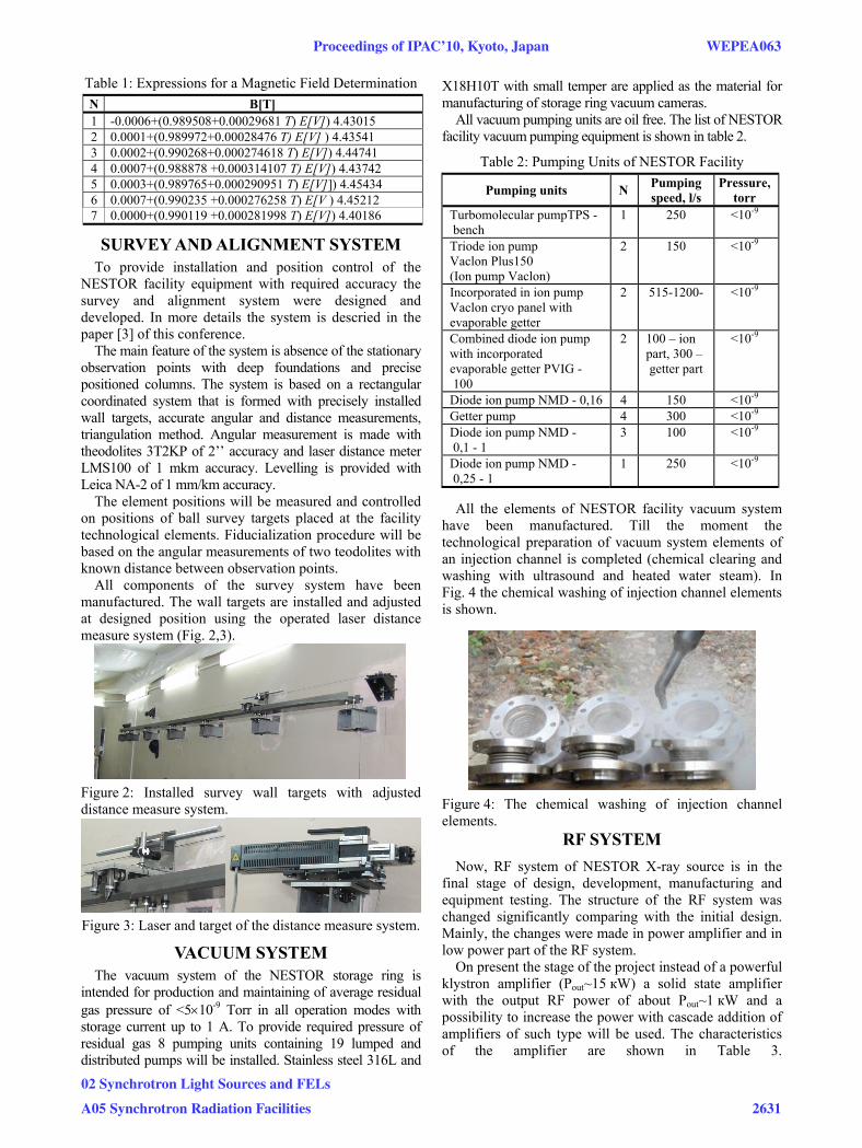
All the elements of NESTOR facility vacuum system have been manufactured. Till the moment the technological preparation of vacuum system elements of an injection channel is completed (chemical clearing and washing with ultrasound and heated water steam). In Fig. 4 the chemical washing of injection channel elements is shown.
Figure 4: The chemical washing of injection channel elements.
RF SYSTEM Now, RF system of NESTOR X-ray source is in the
final stage of design, development, manufacturing and equipment testing. The structure of the RF system was changed significantly comparing with the initial design. Mainly, the changes were made in power amplifier and in low power part of the RF system.
On present the stage of the project instead of a powerful klystron amplifier (Рout~15 кW) a solid state amplifier with the output RF power of about Рout~1 кW and a possibility to increase the power with cascade addition of amplifiers of such type will be used. The characteristics of the amplifier are shown in Table 3.
Proceedings of IPAC’10, Kyoto, Japan WEPEA063
02 Synchrotron Light Sources and FELs
A05 Synchrotron Radiation Facilities 2631
Table 3: RF Amplifier Characteristics Parameters Units Volume
Operating frequency MHz 699.3±1.0 Output power kW 1.0 Gain dB >40 Input and Output impedance Ω 50 Phase noise dB <-65 The design of the low power part of the RF system is
near to the completion and the manufacturing of some system components was already started. The system as a hole will be ready in a half of a year.
Instead of control attenuator on p-i-n diode in the amplitude control loop (АCL) an RF-amplifier with controlled gain will be used. This device will serve as a preamplifier to drive the solid state power amplifier. Instead of varicap-based phase shifter in the phase control loop (PCL) a digital synthesizer (DDS) will be used. This device is a part of the master oscillator (MO) with frequency of 699.3 МHz and it can vary the phase of the RF-signal by software.
Amplitude and phase of RF signals at the input and output of the RF-cavity which are used in ACL and PCL loops will be measured by amplitude-phase meters and will be supplied for the further use to a microcontroller.
Master Oscillator will be designed according tо principles of modern frequency synthesizer on the base of high stable quartz generator, DDS and voltage-controlled oscillator (VCO) with the phase control loop (PLL).
To decrease phase noises for each frequency, required for NESTOR facility operation (349.65 MHz, 699.3 MHz and 2977.2 MHz), the generation of reference signal on the highest frequency will be used with further frequency dividing by 4 or by 8.
The testing of the RF cavity that was manufactured in Budker INP, Novosibirsk, Russia [4] and solid state amplifier TVAU-500 of Ukrainian firm “Quant-Efir” has been carried out.
The RF cavity bandwidth, Q-factor Q0, coupling factor to the RF-power transmission line were checked out in cold test. The results of the measurements of coupling factor β as function of the coupling loop rotation angle α are shown in Fig. 5. As a “zero” angle the orientation of the loop with a magnetic flux parallel to the loop plane was chosen.
Fig. 6 shows RMS divergence of cavity quality factor Q0. The estimated value of Q0 is 22500 ± 790. Testing of the RF cavity bandwidth has shown that its value is not less then ±1 МHz of the middle frequency frf = 699.3 МHz, that is even bigger then it was supposed to get in the project.
The RF-power amplifier was tested at power level of 1 kW. The output and reflected power was controlled with units incorporated in the amplifier. At the frequency of 699.3 MHz the gain was of about 43 dB. Back losses of the circulator were not less then 23 dB. In this regime the amplifier was operated during at least one hour. Operation currents of output transistors were checked with micro controller incorporated in the amplifier and were in the acceptable range ( ≈ 11 А). The temperature
of theirs radiators was 42°С, which is much less then acceptable 70°С.
0 10 20 30 40 50 60 70 80 900,0
0,5
1,0
1,5
2,0
2,5
3,0
Cou
plin
g fa
ctor
Loop rotation angle α, deg Figure 5: Coupling parameter β versus rotation angle of the coupling loop.
20 21 22 23 24 250
1
2
3
4
5
6
Num
ber o
f mea
sure
men
ts
Q 0 (x10 3)
Q 0=22500+-790
Figure 6: RMS divergence of cavity quality factor Q0.
CONCLUSION In the paper the resent results of NESTOR team on
magnetic element characteristic measurements, design and development of survey and alignment system, vacuum and RF system development and testing are presented. The overviewed results make a good background to begin NESTOR facility commissioning in the nearest time.
REFERENCES [1] E. Bulyak et. al, “Compact X-ray Source Based on Compton
Backscattering,” NIM A, 2002, # 487, pp. 241-248. [2] P.Gladkikh et. al, “Lattice of NSC KIPT Compact Intense