10
CEN/TS 14751:2004 Compliant EN 5836:2000 Compliant www.ndt.com.ua TOFD PRO System ΤΜ
| Date post: | 21-Feb-2017 |
| Category: |
Devices & Hardware |
| Upload: | svitlana-priannikova |
| View: | 191 times |
| Download: | 1 times |
CEN/TS 14751:2004Compliant
EN 5836:2000 Compliant
www.ndt.com.ua
TOFD PROSystem
ΤΜ
TOFD PRO System is intended formechanized testing of welded joints usingTime�of�Flight Diffraction (TOFD) tech�nique. The System assures the solution ofthe following tasks � testing the weldedjoints of:
• flat objects;• tubes of medium and large diameters
(with min. outer diameter of 600 mm);• spherical and cylindrical oil and gas
tanks (with min. diameter of 10 m).
PURPOSE
TOFD TECHNIQUE DESCRIPTION,
FEATURES AND COMPLIANCE
WITH STANDARDS
CONFIGURATIONS
OF TESTED WELDED JOINTS:
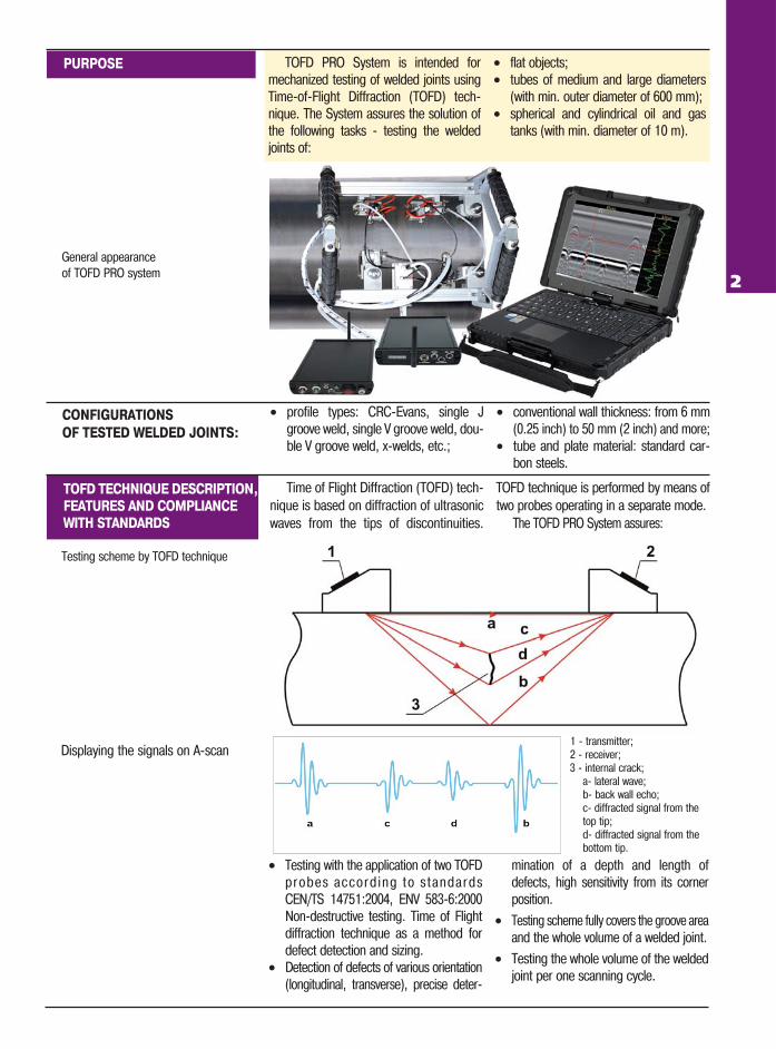
Displaying the signals on A�scan
• profile types: CRC�Evans, single Jgroove weld, single V groove weld, dou�ble V groove weld, x�welds, etc.;
• conventional wall thickness: from 6 mm(0.25 inch) to 50 mm (2 inch) and more;
• tube and plate material: standard car�bon steels.
• Testing with the application of two TOFDprobes acco rd ing t o s t anda rdsCEN/TS 14751:2004, ENV 583�6:2000Non�destructive testing. Time of Flightdiffraction technique as a method fordefect detection and sizing.
• Detection of defects of various orientation(longitudinal, transverse), precise deter�
mination of a depth and length ofdefects, high sensitivity from its cornerposition.
• Testing scheme fully covers the groove areaand the whole volume of a welded joint.
• Testing the whole volume of the weldedjoint per one scanning cycle.
1 � transmitter;2 � receiver;3 � internal crack;
a� lateral wave;b� back wall echo;c� diffracted signal from the top tip;d� diffracted signal from the bottom tip.
Testing scheme by TOFD technique
General appearanceof TOFD PRO system 2
Time of Flight Diffraction (TOFD) tech�nique is based on diffraction of ultrasonicwaves from the tips of discontinuities.
TOFD technique is performed by means oftwo probes operating in a separate mode.
The TOFD PRO System assures:
SOFTWARE
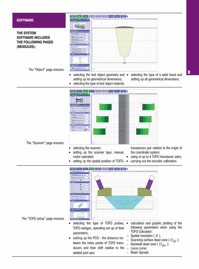
• selecting the test object geometry andsetting up its geometrical dimensions;
• selecting the type of test object material;
• selecting the type of a weld bevel andsetting up all geometrical dimensions.
• selecting the scanner;• setting up the scanner type: manual,
motor�operated;• setting up the spatial position of TOFD�
transducers pair relative to the origin ofthe coordinate system;
• using of up to 4 TOFD transducer pairs; • carrying out the encoder calibration.
• selecting the type of TOFD probes,TOFD wedges, operating set up of theirparameters;
• setting up the PCS � the distance be�tween the index points of TOFD trans�ducers and their shift relative to thewelded joint axis;
• calculation and graphic plotting of thefollowing parameters when using theTOFD Calculator:
— Spatial resolution ( R );— Scanning�surface dead zone ( Dds );— Backwall dead zone ( Ddw );— Locus curve;— Beam Spread.
The “Object” page ensures:
The “Scanner” page ensures:
The “TOFD setup” page ensures:
THE SYSTEM
SOFTWARE INCLUDES
THE FOLLOWING PAGES
(MODULES):
3
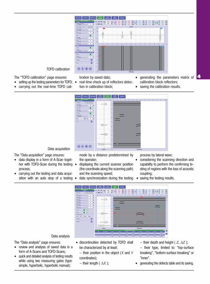
TOFD calibration
The “TOFD calibration” page ensures:• setting up the testing parameters for TOFD;• carrying out the real�time TOFD cali�
bration by saved data;• real�time check up of reflectors detec�
tion in calibration block;
• generating the parameters matrix ofcalibration block reflectors;
• saving the calibration results.
The “Data acquisition” page ensures:• data display in a form of A�Scan toget�
her with TOFD�Scan during the testingprocess;
• carrying out the testing and data acqui�sition with an auto stop of a testing
mode by a distance predetermined bythe operator;
• displaying the current scanner position(the coordinate along the scanning path)and the scanning speed;
• data synchronization during the testing
process by lateral wave;• considering the scanning direction and
capability to perform the confirming te�sting of regions with the loss of acousticcoupling;
• saving the testing results.
Data acquisition
Data analysis
The “Data analysis” page ensures:• review and analysis of saved data in a
form of А�Scans and TOFD�Scans;• quick and detailed analysis of testing results
while using two measuring gates (type:simple, hyperbolic, hyperbolic manual);
• discontinuities detected by TOFD shallbe characterized by at least:— their position in the object (X and Ycoordinates);— their length ( ΔX );
— their depth and height ( Z, ΔZ );— their type, limited to: “top�surfacebreaking”, “bottom�surface breaking” or“inner”.
• generating the defects table and its saving.
4
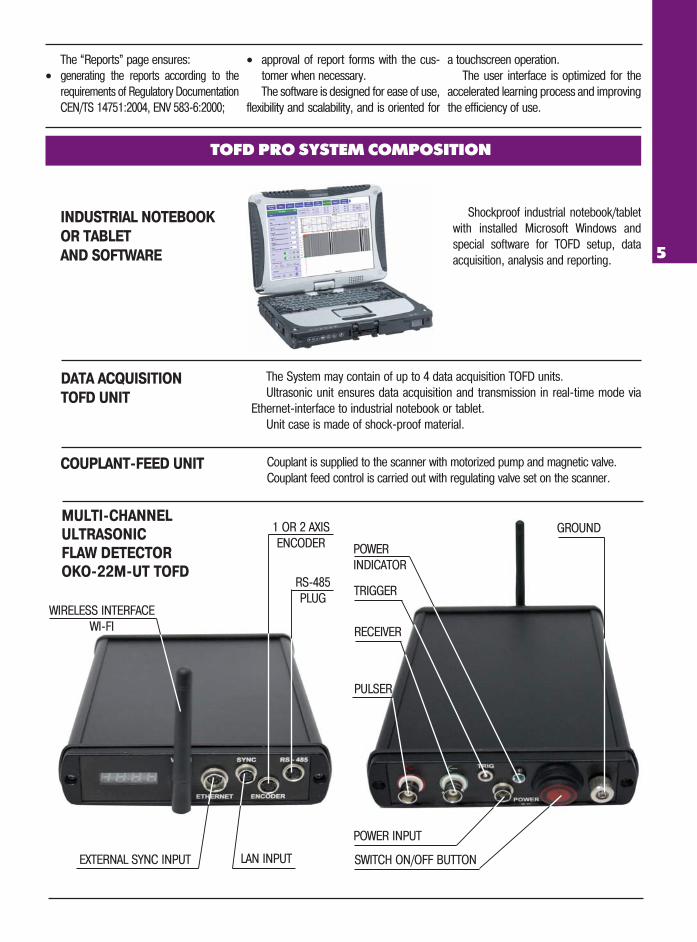
Shockproof industrial notebook/tabletwith installed Microsoft Windows andspecial software for TOFD setup, dataacquisition, analysis and reporting.
Couplant is supplied to the scanner with motorized pump and magnetic valve. Couplant feed control is carried out with regulating valve set on the scanner.
The System may contain of up to 4 data acquisition TOFD units.Ultrasonic unit ensures data acquisition and transmission in real�time mode via
Ethernet�interface to industrial notebook or tablet.Unit case is made of shock�proof material.
TOFD PRO SYSTEM COMPOSITION
INDUSTRIAL NOTEBOOK
OR TABLET
AND SOFTWARE
DATA ACQUISITION
TOFD UNIT
COUPLANT�FEED UNIT
The “Reports” page ensures:• generating the reports according to the
requirements of Regulatory DocumentationCEN/TS 14751:2004, ENV 583�6:2000;
• approval of report forms with the cus�tomer when necessary.The software is designed for ease of use,
flexibility and scalability, and is oriented for
a touchscreen operation.The user interface is optimized for the
accelerated learning process and improvingthe efficiency of use.
5
MULTI�CHANNEL
ULTRASONIC
FLAW DETECTOR
OKO�22M�UT TOFD
POWER INPUT
LAN INPUT
RS�485PLUG
EXTERNAL SYNC INPUT
1 OR 2 AXISENCODER
WIRELESS INTERFACEWI�FI
GROUND
SWITCH ON/OFF BUTTON
POWER INDICATOR
TRIGGER
RECEIVER
PULSER
6
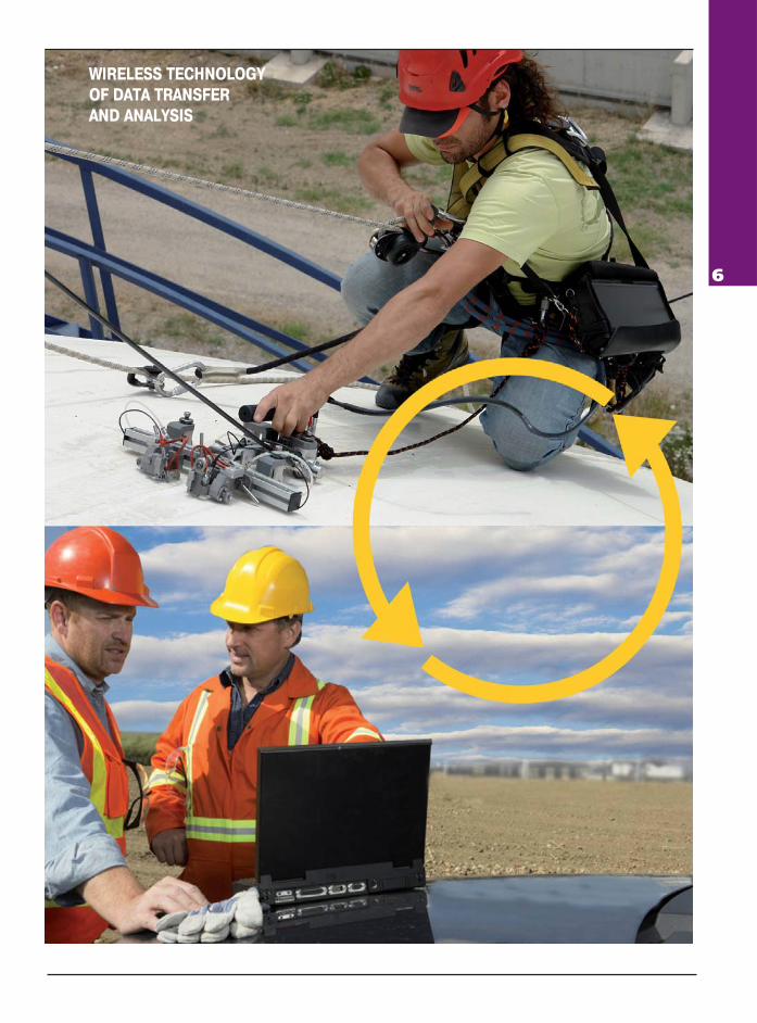
WIRELESS TECHNOLOGY
OF DATA TRANSFER
AND ANALYSIS
7
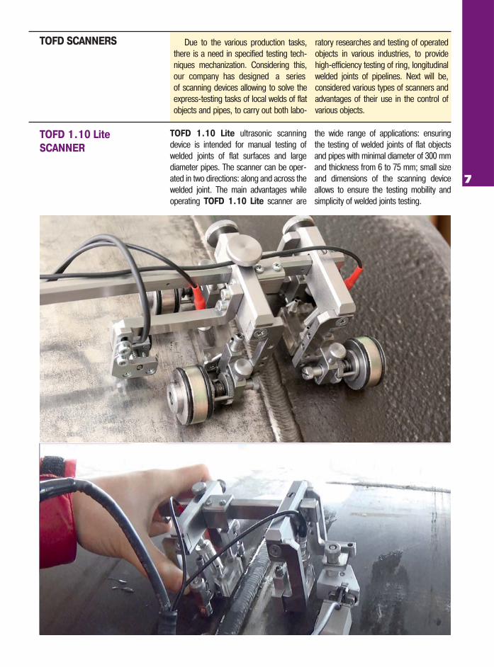
Due to the various production tasks,there is a need in specified testing tech�niques mechanization. Considering this,
of scanning devices allowing to solve theexpress�testing tasks of local welds of flatobjects and pipes, to carry out both labo�
ratory researches and testing of operatedobjects in various industries, to providehigh�efficiency testing of ring, longitudinalwelded joints of pipelines. Next will be,considered various types of scanners andadvantages of their use in the control ofvarious objects.
TOFD SCANNERS
TOFD 1.10 Lite ultrasonic scanningdevice is intended for manual testing ofwelded joints of flat surfaces and largediameter pipes. The scanner can be oper�ated in two directions: along and across thewelded joint. The main advantages whileoperating TOFD 1.10 Lite scanner are
the wide range of applications: ensuringthe testing of welded joints of flat objectsand pipes with minimal diameter of 300 mmand thickness from 6 to 75 mm; small sizeand dimensions of the scanning deviceallows to ensure the testing mobility andsimplicity of welded joints testing.
TOFD 1.10 Lite
SCANNER
our company has designed a series
8
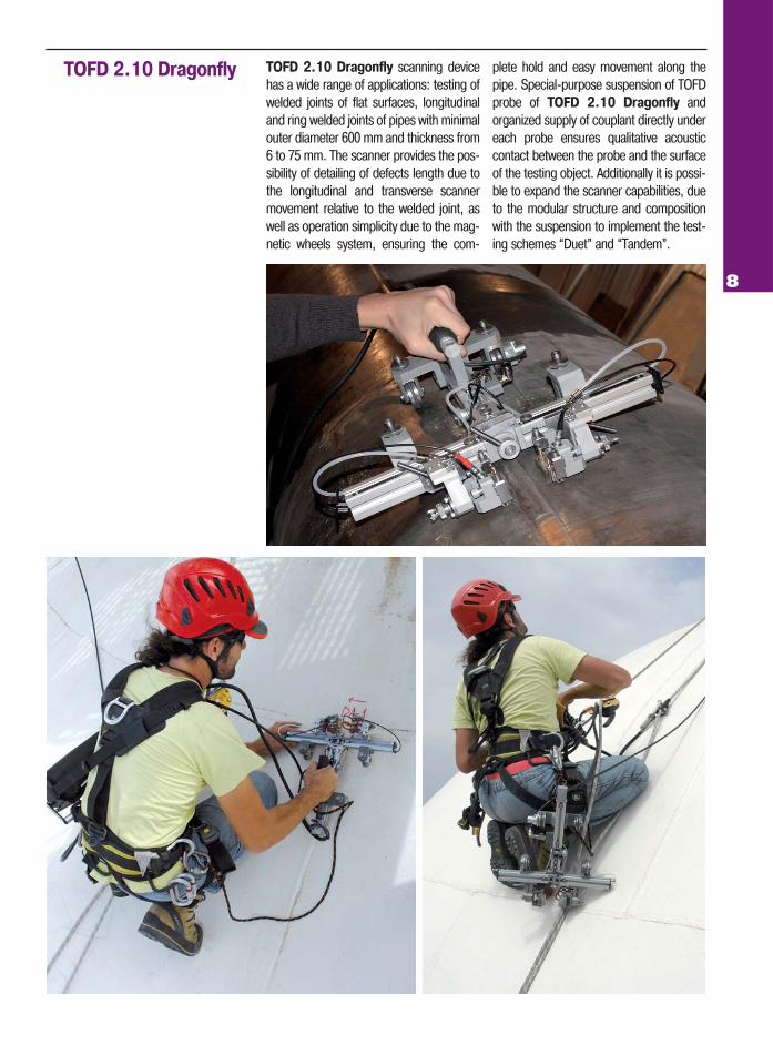
TOFD 2.10 Dragonfly TOFD 2.10 Dragonfly scanning devicehas a wide range of applications: testing ofwelded joints of flat surfaces, longitudinaland ring welded joints of pipes with minimalouter diameter 600 mm and thickness from6 to 75 mm. The scanner provides the pos�sibility of detailing of defects length due tothe longitudinal and transverse scannermovement relative to the welded joint, aswell as operation simplicity due to the mag�netic wheels system, ensuring the com�
plete hold and easy movement along thepipe. Special�purpose suspension of TOFDprobe of TOFD 2.10 Dragonfly andorganized supply of couplant directly undereach probe ensures qualitative acousticcontact between the probe and the surfaceof the testing object. Additionally it is possi�ble to expand the scanner capabilities, dueto the modular structure and compositionwith the suspension to implement the test�ing schemes “Duet” and “Tandem”.
9
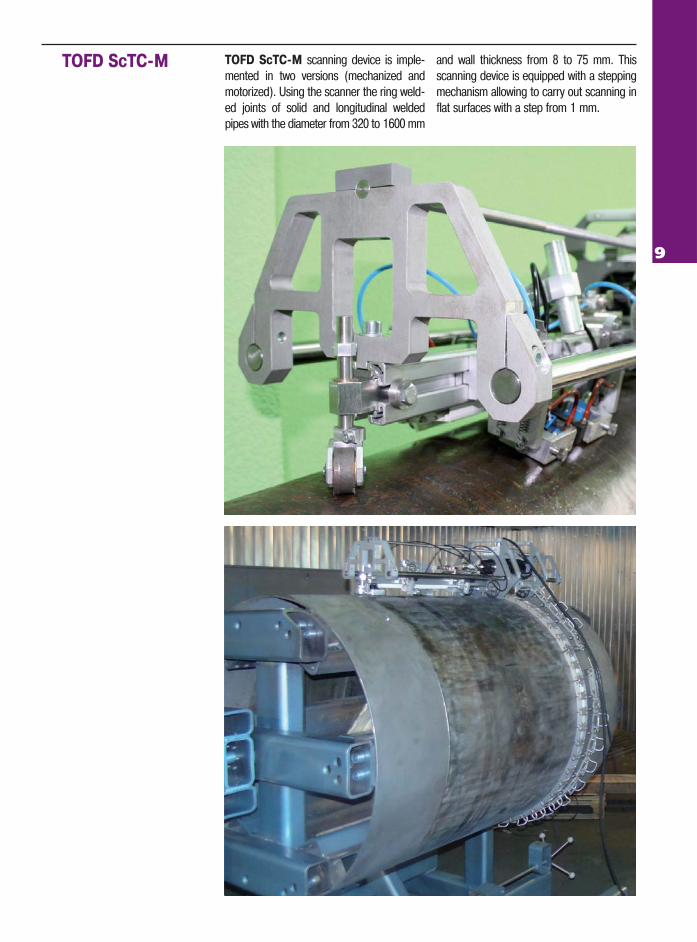
TOFD ScTC�M scanning device is imple�mented in two versions (mechanized andmotorized). Using the scanner the ring weld�ed joints of solid and longitudinal weldedpipes with the diameter from 320 to 1600 mm
and wall thickness from 8 to 75 mm. Thisscanning device is equipped with a steppingmechanism allowing to carry out scanning inflat surfaces with a step from 1 mm.
TOFD ScTC�M
ULTRACON�SERVICE LLCP.O.Box 31, Kiev 04111, Ukraine, tel./fax: +38 044 531�37�27(26)
E�mail:[email protected] www.ndt.com.ua
TOFD UNIT SPECIFICATIONS
• Ultrasonic transducers connector _ _ _ _ _ _ _ _ _2 (Lemo)• A/D converter _ _ _ _ _ _ _ _ _ _ _ _ _ _ _ _10 bit (100 MHz)• Initial pulse _ _ _ _ _ _ _ _ _ _ _ _ _ _ _ _ _ _ _ _ 50 — 400 V • Gain _ _ _ _ _ _ _ _ _ _ _ _ _ _ _ _ _ _ _ _ _ _ _ _ _ _ 110 dB• Rectification _ _ _ _ _ _full wave, + half wave, � half wave
_ _ _ _ _ _ _ _ _ _ _ _ _ _ _ _ _ _ _ _ _ _and radio frequency• Bandwidth _ _ _ _ _ _ _ _ _ _ _ _ _ _ _ _ _ _ _ _ 0.2 � 27 MHz
• Encoder _ _ _ _ _ _ _ _ _ _ _ _ _ _ _ _ _ 2� axis encoder line• PRF _ _ _ _ _ _ _ _ _ _ _ _ _ _ _ _ _ _ _ _ _ _ _ _15 � 2000 Hz• Real�time averaging _ _ _ _ _ _ _ _ _ _1, 2, 4, 8, 16, 32, 64• Maximum scanning velocity _ _ _ _ _ _ _ _ _ _ _ _100 mm/s• Operating
temperature range _ _ _ _ _from minus 20 0С to plus 50 0С
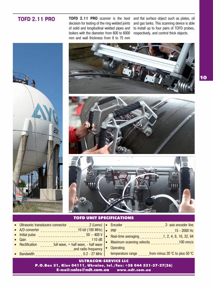
TOFD 2.11 PRO scanner is the bestdecision for testing of the ring welded jointsof solid and longitudinal welded pipes andboilers with the diameter from 600 to 6000mm and wall thickness from 8 to 75 mm
and flat surface object such as plates, oiland gas tanks. This scanning device is ableto install up to four pairs of TOFD probes,respectively, and control thick objects.
TOFD 2.11 PRO
10


