64
User’s manual FLIR TG167
User’s manualFLIR TG167


Important noteBefore operating the device, you must read, understand, and follow all instructions, warnings, cautions, and legal disclaimers.Důležitá poznámkaPřed použitím zařízení si přečtěte veškeré pokyny, upozornění, varování a vyvázání se ze záruky, ujistěte se, že jim rozumíte, a řiďtese jimi.Vigtig meddelelseFør du betjener enheden, skal du du læse, forstå og følge alle anvisninger, advarsler, sikkerhedsforanstaltninger ogansvarsfraskrivelser.Wichtiger HinweisBevor Sie das Gerät in Betrieb nehmen, lesen, verstehen und befolgen Sie unbedingt alle Anweisungen, Warnungen,Vorsichtshinweise und HaftungsausschlüsseΣημαντική σημείωσηΠριν από τη λειτουργία της συσκευής, πρέπει να διαβάσετε, να κατανοήσετε και να ακολουθήσετε όλες τις οδηγίες,προειδοποιήσεις, προφυλάξεις και νομικές αποποιήσεις.Nota importanteAntes de usar el dispositivo, debe leer, comprender y seguir toda la información sobre instrucciones, advertencias, precauciones yrenuncias de responsabilidad.Tärkeä huomautusEnnen laitteen käyttämistä on luettava ja ymmärrettävä kaikki ohjeet, vakavat varoitukset, varoitukset ja lakitiedotteet sekänoudatettava niitä.Remarque importanteAvant d'utiliser l'appareil, vous devez lire, comprendre et suivre l'ensemble des instructions, avertissements, mises en garde etclauses légales de non-responsabilité.Fontos megjegyzésAz eszköz használata előtt figyelmesen olvassa el és tartsa be az összes utasítást, figyelmeztetést, óvintézkedést és joginyilatkozatot.Nota importantePrima di utilizzare il dispositivo, è importante leggere, capire e seguire tutte le istruzioni, avvertenze, precauzioni ed esclusioni diresponsabilità legali.重要な注意デバイスをご使用になる前に、あらゆる指示、警告、注意事項、および免責条項をお読み頂き、その内容を理解して従ってください。중요한참고사항장치를작동하기전에반드시다음의사용설명서와경고,주의사항,법적책임제한을읽고이해하며따라야합니다.ViktigFør du bruker enheten, må du lese, forstå og følge instruksjoner, advarsler og informasjon om ansvarsfraskrivelse.Belangrijke opmerkingZorg ervoor dat u, voordat u het apparaat gaat gebruiken, alle instructies, waarschuwingen en juridische informatie hebtdoorgelezen en begrepen, en dat u deze opvolgt en in acht neemt.Ważna uwagaPrzed rozpoczęciem korzystania z urządzenia należy koniecznie zapoznać się z wszystkimi instrukcjami, ostrzeżeniami,przestrogami i uwagami prawnymi. Należy zawsze postępować zgodnie z zaleceniami tam zawartymi.Nota importanteAntes de utilizar o dispositivo, deverá proceder à leitura e compreensão de todos os avisos, precauções, instruções e isenções deresponsabilidade legal e assegurar-se do seu cumprimento.Важное примечаниеДо того, как пользоваться устройством, вам необходимо прочитать и понять все предупреждения, предостережения июридические ограничения ответственности и следовать им.Viktig informationInnan du använder enheten måste du läsa, förstå och följa alla anvisningar, varningar, försiktighetsåtgärder ochansvarsfriskrivningar.Önemli notCihazı çalıştırmadan önce tüm talimatları, uyarıları, ikazları ve yasal açıklamaları okumalı, anlamalı ve bunlara uymalısınız.重要注意事项在操作设备之前,您必须阅读、理解并遵循所有说明、警告、注意事项和法律免责声明。重要注意事項操作裝置之前,您務必閱讀、了解並遵循所有說明、警告、注意事項與法律免責聲明。

User’s manualFLIR TG167
#T559974; r.33562/33594; en-US v

Table of contents
1 Disclaimers ......................................................................................11.1 Legal disclaimer .......................................................................11.2 Usage statistics ........................................................................11.3 Changes to registry ...................................................................11.4 U.S. Government Regulations......................................................11.5 Copyright ................................................................................11.6 Quality assurance .....................................................................11.7 Patents ...................................................................................11.8 EULATerms ............................................................................11.9 EULATerms ............................................................................1
2 Safety information .............................................................................33 Notice to user ...................................................................................4
3.1 User-to-user forums ..................................................................43.2 Calibration...............................................................................43.3 Accuracy ................................................................................43.4 Disposal of electronic waste ........................................................43.5 Training ..................................................................................43.6 Documentation updates .............................................................43.7 Important note about this manual..................................................43.8 Note about authoritative versions..................................................4
4 Customer help ..................................................................................54.1 General ..................................................................................54.2 Submitting a question ................................................................54.3 Downloads ..............................................................................6
5 Introduction......................................................................................76 Quick start guide ...............................................................................87 Description.......................................................................................9
7.1 View from the front ....................................................................97.1.1 Figure..........................................................................97.1.2 Explanation...................................................................9
7.2 View from the rear.....................................................................97.2.1 Figure..........................................................................97.2.2 Explanation...................................................................9
7.3 View from the top.................................................................... 107.3.1 Figure........................................................................ 107.3.2 Explanation................................................................. 10
7.4 View from the bottom............................................................... 107.4.1 Figure........................................................................ 107.4.2 Explanation................................................................. 10
7.5 Infrared imager field of view — view from the top ........................... 107.6 IR imager field of view — view from the side ................................. 117.7 Laser pointers ........................................................................ 11
7.7.1 General...................................................................... 117.7.2 Laser warning label....................................................... 117.7.3 Laser rules and regulations ............................................ 11
7.8 Screen elements .................................................................... 127.8.1 Figure........................................................................ 127.8.2 Explanation................................................................. 127.8.3 Status icons and indicators............................................. 12
8 Operation ....................................................................................... 138.1 Charging the battery ................................................................ 13
8.1.1 Charging the battery using the power supply ...................... 138.1.2 Charging the battery using a computer.............................. 13
8.2 Turning on and turning off the camera.......................................... 13
#T559974; r.33562/33594; en-US vii
Table of contents
8.3 Measuring temperatures........................................................... 138.3.1 General...................................................................... 138.3.2 Procedure .................................................................. 13
8.4 Saving an image..................................................................... 148.4.1 General...................................................................... 148.4.2 Naming convention....................................................... 148.4.3 Procedure .................................................................. 14
8.5 Viewing a saved image ............................................................ 148.5.1 General...................................................................... 148.5.2 Procedure .................................................................. 15
8.6 Deleting all images.................................................................. 158.6.1 General...................................................................... 158.6.2 Procedure .................................................................. 15
8.7 Changing the settings .............................................................. 158.7.1 General...................................................................... 158.7.2 Palette ....................................................................... 168.7.3 Emissivity ................................................................... 168.7.4 Laser pointer ............................................................... 178.7.5 Temperature unit .......................................................... 178.7.6 Crosshair ................................................................... 178.7.7 Auto Power Off ............................................................ 188.7.8 Date and time.............................................................. 188.7.9 Firmware information and calibration date.......................... 19
9 Technical data................................................................................. 209.1 Note about technical data ......................................................... 209.2 Note about authoritative versions................................................ 209.3 FLIR TG167 (Global) ............................................................... 21
10 Mechanical drawings ....................................................................... 2411 Cleaning the camera ........................................................................ 26
11.1 Camera housing, cables, and other items..................................... 2611.1.1 Liquids....................................................................... 2611.1.2 Equipment .................................................................. 2611.1.3 Procedure .................................................................. 26
11.2 Infrared lens .......................................................................... 2611.2.1 Liquids....................................................................... 2611.2.2 Equipment .................................................................. 2611.2.3 Procedure .................................................................. 26
12 Application examples....................................................................... 2712.1 Moisture & water damage ......................................................... 27
12.1.1 General...................................................................... 2712.1.2 Figure........................................................................ 27
12.2 Faulty contact in socket ............................................................ 2712.2.1 General...................................................................... 2712.2.2 Figure........................................................................ 27
12.3 Oxidized socket...................................................................... 2812.3.1 General...................................................................... 2812.3.2 Figure........................................................................ 28
12.4 Insulation deficiencies.............................................................. 2912.4.1 General...................................................................... 2912.4.2 Figure........................................................................ 29
12.5 Draft .................................................................................... 2912.5.1 General...................................................................... 2912.5.2 Figure........................................................................ 29
#T559974; r.33562/33594; en-US viii
Table of contents
13 About FLIR Systems ........................................................................ 3113.1 More than just an infrared camera .............................................. 3213.2 Sharing our knowledge ............................................................ 3213.3 Supporting our customers......................................................... 32
14 Glossary ........................................................................................ 3415 History of infrared technology........................................................... 3716 Emissivity tables ............................................................................. 40
16.1 References............................................................................ 4016.2 Tables .................................................................................. 40
#T559974; r.33562/33594; en-US ix

Disclaimers1
1.1 Legal disclaimerAll products manufactured by FLIR Systems are warranted against defectivematerials and workmanship for a period of one (1) year from the delivery dateof the original purchase, provided such products have been under normalstorage, use and service, and in accordance with FLIR Systems instruction.
Uncooled handheld infrared cameras manufactured by FLIR Systems arewarranted against defective materials and workmanship for a period of two(2) years from the delivery date of the original purchase, provided such prod-ucts have been under normal storage, use and service, and in accordancewith FLIR Systems instruction, and provided that the camera has been regis-tered within 60 days of original purchase.
Detectors for uncooled handheld infrared cameras manufactured by FLIRSystems are warranted against defective materials and workmanship for aperiod of ten (10) years from the delivery date of the original purchase, pro-vided such products have been under normal storage, use and service, andin accordance with FLIR Systems instruction, and provided that the camerahas been registered within 60 days of original purchase.
Products which are not manufactured by FLIR Systems but included in sys-tems delivered by FLIR Systems to the original purchaser, carry the warranty,if any, of the particular supplier only. FLIR Systems has no responsibilitywhatsoever for such products.
The warranty extends only to the original purchaser and is not transferable. Itis not applicable to any product which has been subjected to misuse, neglect,accident or abnormal conditions of operation. Expendable parts are excludedfrom the warranty.
In the case of a defect in a product covered by this warranty the product mustnot be further used in order to prevent additional damage. The purchasershall promptly report any defect to FLIR Systems or this warranty will notapply.
FLIR Systems will, at its option, repair or replace any such defective productfree of charge if, upon inspection, it proves to be defective in material or work-manship and provided that it is returned to FLIR Systems within the said one-year period.
FLIR Systems has no other obligation or liability for defects than those setforth above.
No other warranty is expressed or implied. FLIR Systems specifically dis-claims the implied warranties of merchantability and fitness for a particularpurpose.
FLIR Systems shall not be liable for any direct, indirect, special, incidental orconsequential loss or damage, whether based on contract, tort or any otherlegal theory.
This warranty shall be governed by Swedish law.
Any dispute, controversy or claim arising out of or in connection with this war-ranty, shall be finally settled by arbitration in accordance with the Rules of theArbitration Institute of the Stockholm Chamber of Commerce. The place of ar-bitration shall be Stockholm. The language to be used in the arbitral proceed-ings shall be English.
1.2 Usage statisticsFLIR Systems reserves the right to gather anonymous usage statistics to helpmaintain and improve the quality of our software and services.
1.3 Changes to registryThe registry entry HKEY_LOCAL_MACHINE\SYSTEM\CurrentControlSet\Control\Lsa\LmCompatibilityLevel will be automatically changed to level 2 ifthe FLIR Camera Monitor service detects a FLIR camera connected to thecomputer with a USB cable. The modification will only be executed if thecamera device implements a remote network service that supports networklogons.
1.4 U.S. Government RegulationsThis product may be subject to U.S. Export Regulations. Please send any in-quiries to [email protected].
1.5 Copyright© 2016, FLIR Systems, Inc. All rights reserved worldwide. No parts of thesoftware including source code may be reproduced, transmitted, transcribedor translated into any language or computer language in any form or by anymeans, electronic, magnetic, optical, manual or otherwise, without the priorwritten permission of FLIR Systems.
The documentation must not, in whole or part, be copied, photocopied, re-produced, translated or transmitted to any electronic medium or machinereadable form without prior consent, in writing, from FLIR Systems.
Names and marks appearing on the products herein are either registeredtrademarks or trademarks of FLIR Systems and/or its subsidiaries. All othertrademarks, trade names or company names referenced herein are used foridentification only and are the property of their respective owners.
1.6 Quality assuranceThe Quality Management System under which these products are developedand manufactured has been certified in accordance with the ISO 9001standard.
FLIR Systems is committed to a policy of continuous development; thereforewe reserve the right to make changes and improvements on any of the prod-ucts without prior notice.
1.7 PatentsOne or several of the following patents and/or design patents may apply tothe products and/or features. Additional pending patents and/or pending de-sign patents may also apply.
000279476-0001; 000439161; 000499579-0001; 000653423; 000726344;000859020; 001106306-0001; 001707738; 001707746; 001707787;001776519; 001954074; 002021543; 002058180; 002249953; 002531178;0600574-8; 1144833; 1182246; 1182620; 1285345; 1299699; 1325808;1336775; 1391114; 1402918; 1404291; 1411581; 1415075; 1421497;1458284; 1678485; 1732314; 2106017; 2107799; 2381417; 3006596;3006597; 466540; 483782; 484155; 4889913; 5177595; 60122153.2;602004011681.5-08; 6707044; 68657; 7034300; 7110035; 7154093;7157705; 7237946; 7312822; 7332716; 7336823; 7544944; 7667198;7809258 B2; 7826736; 8,153,971; 8,823,803; 8,853,631; 8018649 B2;8212210 B2; 8289372; 8354639 B2; 8384783; 8520970; 8565547; 8595689;8599262; 8654239; 8680468; 8803093; D540838; D549758; D579475;D584755; D599,392; D615,113; D664,580; D664,581; D665,004; D665,440;D677298; D710,424 S; D718801; DI6702302-9; DI6903617-9; DI7002221-6;DI7002891-5; DI7002892-3; DI7005799-0; DM/057692; DM/061609; EP2115696 B1; EP2315433; SE 0700240-5; US 8340414 B2; ZL201330267619.5; ZL01823221.3; ZL01823226.4; ZL02331553.9;ZL02331554.7; ZL200480034894.0; ZL200530120994.2;ZL200610088759.5; ZL200630130114.4; ZL200730151141.4;ZL200730339504.7; ZL200820105768.8; ZL200830128581.2;ZL200880105236.4; ZL200880105769.2; ZL200930190061.9;ZL201030176127.1; ZL201030176130.3; ZL201030176157.2;ZL201030595931.3; ZL201130442354.9; ZL201230471744.3;ZL201230620731.8.
1.8 EULATerms• You have acquired a device (“INFRARED CAMERA”) that includes soft-
ware licensed by FLIR Systems AB from Microsoft Licensing, GP or itsaffiliates (“MS”). Those installed software products of MS origin, as wellas associated media, printed materials, and “online” or electronic docu-mentation (“SOFTWARE”) are protected by international intellectualproperty laws and treaties. The SOFTWARE is licensed, not sold. Allrights reserved.
• IF YOU DO NOTAGREE TO THIS END USER LICENSE AGREEMENT(“EULA”), DO NOT USE THE DEVICE OR COPY THE SOFTWARE. IN-STEAD, PROMPTLYCONTACT FLIR Systems AB FOR INSTRUC-TIONS ON RETURN OF THE UNUSED DEVICE(S) FOR A REFUND.ANY USE OF THE SOFTWARE, INCLUDING BUT NOT LIMITED TOUSE ON THE DEVICE, WILL CONSTITUTE YOUR AGREEMENT TOTHIS EULA (OR RATIFICATION OFANY PREVIOUS CONSENT).
• GRANTOF SOFTWARE LICENSE. This EULA grants you the followinglicense:
◦ You may use the SOFTWARE only on the DEVICE.◦ NOT FAULT TOLERANT. THE SOFTWARE IS NOT FAULT TOL-
ERANT. FLIR Systems AB HAS INDEPENDENTLY DETERMINEDHOW TO USE THE SOFTWARE IN THE DEVICE, AND MS HASRELIED UPON FLIR Systems AB TO CONDUCT SUFFICIENTTESTING TO DETERMINE THAT THE SOFTWARE IS SUITABLEFOR SUCH USE.
◦ NOWARRANTIES FOR THE SOFTWARE. THE SOFTWARE isprovided “AS IS” and with all faults. THE ENTIRE RISK AS TOSATISFACTORYQUALITY, PERFORMANCE, ACCURACY, ANDEFFORT (INCLUDING LACKOF NEGLIGENCE) IS WITH YOU.ALSO, THERE IS NOWARRANTYAGAINST INTERFERENCEWITH YOUR ENJOYMENTOF THE SOFTWARE OR AGAINSTINFRINGEMENT. IF YOU HAVE RECEIVED ANY WARRANTIESREGARDING THE DEVICE OR THE SOFTWARE, THOSE WAR-RANTIES DO NOTORIGINATE FROM, AND ARE NOT BINDINGON, MS.
◦ No Liability for Certain Damages. EXCEPTAS PROHIBITED BYLAW, MS SHALL HAVE NO LIABILITY FOR ANY INDIRECT,SPECIAL, CONSEQUENTIAL OR INCIDENTAL DAMAGESARISING FROM OR IN CONNECTIONWITH THE USE OR PER-FORMANCE OF THE SOFTWARE. THIS LIMITATION SHALLAPPLY EVEN IFANY REMEDY FAILS OF ITS ESSENTIAL PUR-POSE. IN NO EVENT SHALL MS BE LIABLE FOR ANYAMOUNT IN EXCESS OF U.S. TWO HUNDRED FIFTY DOL-LARS (U.S.$250.00).
◦ Limitations on Reverse Engineering, Decompilation, and Dis-assembly. You may not reverse engineer, decompile, or disas-semble the SOFTWARE, except and only to the extent that suchactivity is expressly permitted by applicable law notwithstandingthis limitation.
◦ SOFTWARE TRANSFER ALLOWED BUT WITH RESTRIC-TIONS. You may permanently transfer rights under this EULA onlyas part of a permanent sale or transfer of the Device, and only ifthe recipient agrees to this EULA. If the SOFTWARE is an up-grade, any transfer must also include all prior versions of theSOFTWARE.
◦ EXPORT RESTRICTIONS. You acknowledge that SOFTWARE issubject to U.S. export jurisdiction. You agree to comply with all ap-plicable international and national laws that apply to the SOFT-WARE, including the U.S. Export Administration Regulations, aswell as end-user, end-use and destination restrictions issued by U.S. and other governments. For additional information see http://www.microsoft.com/exporting/.
1.9 EULATermsQt4 Core and Qt4 GUI, Copyright ©2013 Nokia Corporation and FLIR Sys-tems AB. This Qt library is a free software; you can redistribute it and/or mod-ify it under the terms of the GNU Lesser General Public License as publishedby the Free Software Foundation; either version 2.1 of the License, or (at youroption) any later version. This library is distributed in the hope that it will beuseful, but WITHOUTANY WARRANTY; without even the implied warranty ofMERCHANTABILITYor FITNESS FOR A PARTICULAR PURPOSE. See theGNU Lesser General Public License, http://www.gnu.org/licenses/lgpl-2.1.
#T559974; r.33562/33594; en-US 1

Disclaimers1
html. The source code for the libraries Qt4 Core and Qt4 GUI may be re-quested from FLIR Systems AB.
#T559974; r.33562/33594; en-US 2
Safety information2
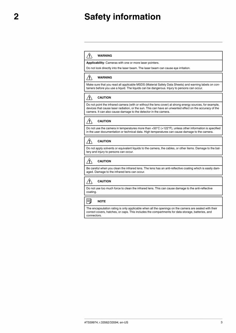
WARNING
Applicability: Cameras with one or more laser pointers.
Do not look directly into the laser beam. The laser beam can cause eye irritation.
WARNING
Make sure that you read all applicable MSDS (Material Safety Data Sheets) and warning labels on con-tainers before you use a liquid. The liquids can be dangerous. Injury to persons can occur.
CAUTION
Do not point the infrared camera (with or without the lens cover) at strong energy sources, for example,devices that cause laser radiation, or the sun. This can have an unwanted effect on the accuracy of thecamera. It can also cause damage to the detector in the camera.
CAUTION
Do not use the camera in temperatures more than +50°C (+122°F), unless other information is specifiedin the user documentation or technical data. High temperatures can cause damage to the camera.
CAUTION
Do not apply solvents or equivalent liquids to the camera, the cables, or other items. Damage to the bat-tery and injury to persons can occur.
CAUTION
Be careful when you clean the infrared lens. The lens has an anti-reflective coating which is easily dam-aged. Damage to the infrared lens can occur.
CAUTION
Do not use too much force to clean the infrared lens. This can cause damage to the anti-reflectivecoating.
NOTE
The encapsulation rating is only applicable when all the openings on the camera are sealed with theircorrect covers, hatches, or caps. This includes the compartments for data storage, batteries, andconnectors.
#T559974; r.33562/33594; en-US 3
Notice to user3
3.1 User-to-user forums
Exchange ideas, problems, and infrared solutions with fellow thermographers around theworld in our user-to-user forums. To go to the forums, visit:
http://www.infraredtraining.com/community/boards/
3.2 Calibration
We recommend that you send in the camera for calibration once a year. Contact your lo-cal sales office for instructions on where to send the camera.
3.3 Accuracy
For very accurate results, we recommend that you wait 5 minutes after you have startedthe camera before measuring a temperature.
3.4 Disposal of electronic waste
As with most electronic products, this equipment must be disposed of in an environmen-tally friendly way, and in accordance with existing regulations for electronic waste.
Please contact your FLIR Systems representative for more details.
3.5 Training
To read about infrared training, visit:
• http://www.infraredtraining.com• http://www.irtraining.com• http://www.irtraining.eu
3.6 Documentation updates
Our manuals are updated several times per year, and we also issue product-critical notifi-cations of changes on a regular basis.
To access the latest manuals and notifications, go to the Download tab at:
http://support.flir.com
It only takes a few minutes to register online. In the download area you will also find thelatest releases of manuals for our other products, as well as manuals for our historicaland obsolete products.
3.7 Important note about this manual
FLIR Systems issues generic manuals that cover several cameras within a model line.
This means that this manual may contain descriptions and explanations that do not applyto your particular camera model.
3.8 Note about authoritative versions
The authoritative version of this publication is English. In the event of divergences due totranslation errors, the English text has precedence.
Any late changes are first implemented in English.
#T559974; r.33562/33594; en-US 4
Customer help4
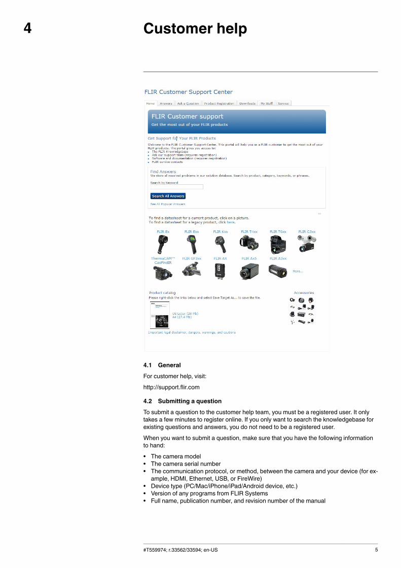
4.1 General
For customer help, visit:
http://support.flir.com
4.2 Submitting a question
To submit a question to the customer help team, you must be a registered user. It onlytakes a few minutes to register online. If you only want to search the knowledgebase forexisting questions and answers, you do not need to be a registered user.
When you want to submit a question, make sure that you have the following informationto hand:
• The camera model• The camera serial number• The communication protocol, or method, between the camera and your device (for ex-ample, HDMI, Ethernet, USB, or FireWire)
• Device type (PC/Mac/iPhone/iPad/Android device, etc.)• Version of any programs from FLIR Systems• Full name, publication number, and revision number of the manual
#T559974; r.33562/33594; en-US 5
Customer help4
4.3 Downloads
On the customer help site you can also download the following:
• Firmware updates for your infrared camera.• Program updates for your PC/Mac software.• Freeware and evaluation versions of PC/Mac software.• User documentation for current, obsolete, and historical products.• Mechanical drawings (in *.dxf and *.pdf format).• Cad data models (in *.stp format).• Application stories.• Technical datasheets.• Product catalogs.
#T559974; r.33562/33594; en-US 6
Introduction5
Thank you for choosing a FLIR TG167 from FLIR Systems.
FLIR’s new FLIR TG167 imaging infrared thermometer bridges the gap between single-spot infrared thermometers and FLIR’s legendary thermal cameras. Equipped withFLIR’s exclusive Lepton micro thermal camera, the FLIR TG167 shows you where poten-tial problems are brewing and where to aim your spot.
The FLIR TG167 lets you see heat patterns, reliably measure temperature, and store im-ages and data. Its menu uses intuitive icons, making it simple to operate. The FLIRTG167 also makes documentation easy by saving images you can download from theMicro SD card or over a USB connection and use for reports.
Main features:
• See the heat and speed up troubleshooting.• Know where to measure temperature.• Grab and go simplicity—no special training required.• Pocket portable to fit a crowded tool bag.• Rugged and reliable.
#T559974; r.33562/33594; en-US 7
Quick start guide6
Follow this procedure:
1. Charge the battery. You can do this in two different ways:
• Charge the battery using a USB cable connected to the power supply.• Charge the battery using a USB cable connected to a computer.Note Charging the camera using a USB cable connected to a computer takesconsiderably longer than using the FLIR power supply or the FLIR stand-alonebattery charger.
2. Push and hold the button for more than 2 seconds to turn on the camera.3. Aim the camera toward an area or object of interest and view the thermal image. The
relative temperature is represented by color, hot to cold (light to dark, respectively).The infrared thermometer reading (upper left on the screen) represents the tempera-ture at the position of the crosshair.
4. Pull and hold the trigger. This activates the two laser pointers.5. Release the trigger to freeze/capture the image. Push the button to save the im-
age or push the button to discard the image.
#T559974; r.33562/33594; en-US 8
Description7
7.1 View from the front
7.1.1 Figure
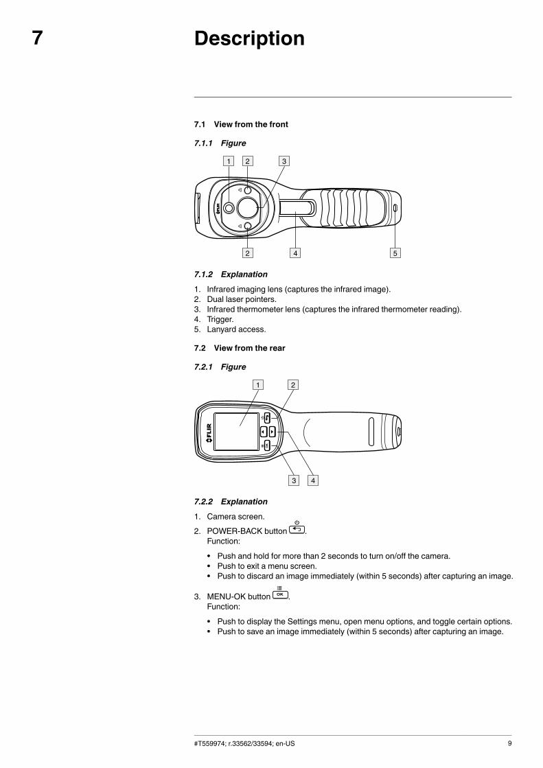
7.1.2 Explanation
1. Infrared imaging lens (captures the infrared image).2. Dual laser pointers.3. Infrared thermometer lens (captures the infrared thermometer reading).4. Trigger.5. Lanyard access.
7.2 View from the rear
7.2.1 Figure
7.2.2 Explanation
1. Camera screen.2. POWER-BACK button .
Function:
• Push and hold for more than 2 seconds to turn on/off the camera.• Push to exit a menu screen.• Push to discard an image immediately (within 5 seconds) after capturing an image.
3. MENU-OK button .Function:
• Push to display the Settings menu, open menu options, and toggle certain options.• Push to save an image immediately (within 5 seconds) after capturing an image.
#T559974; r.33562/33594; en-US 9
Description7
4. UP-DOWN buttons .Function:
• Push to navigate the Settings menu and select settings.• Push and hold the button for 4 seconds to open the image archive.• Push to scroll through saved images in the image archive.
7.3 View from the top
7.3.1 Figure
7.3.2 Explanation
1. Compartment for the Micro USB port and the Micro SD card slot.
7.4 View from the bottom
7.4.1 Figure
7.4.2 Explanation
1. Tripod mount.2. Lanyard access.
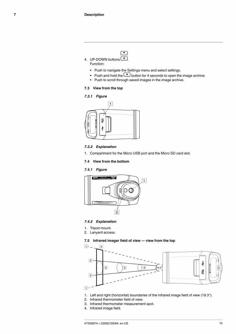
7.5 Infrared imager field of view— view from the top
1. Left and right (horizontal) boundaries of the infrared image field of view (19.3°).2. Infrared thermometer field of view.3. Infrared thermometer measurement spot.4. Infrared image field.
#T559974; r.33562/33594; en-US 10
Description7
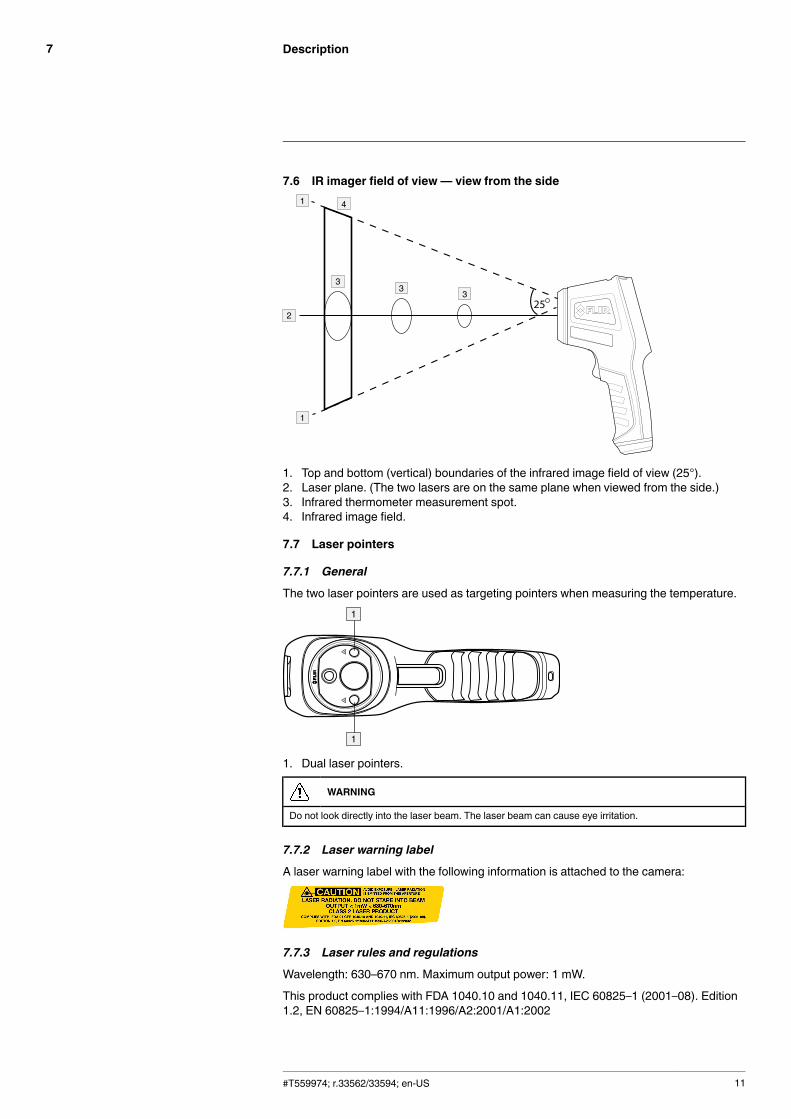
7.6 IR imager field of view— view from the side
1. Top and bottom (vertical) boundaries of the infrared image field of view (25°).2. Laser plane. (The two lasers are on the same plane when viewed from the side.)3. Infrared thermometer measurement spot.4. Infrared image field.
7.7 Laser pointers
7.7.1 General
The two laser pointers are used as targeting pointers when measuring the temperature.
1. Dual laser pointers.
WARNING
Do not look directly into the laser beam. The laser beam can cause eye irritation.
7.7.2 Laser warning label
A laser warning label with the following information is attached to the camera:
7.7.3 Laser rules and regulations
Wavelength: 630–670 nm. Maximum output power: 1 mW.
This product complies with FDA 1040.10 and 1040.11, IEC 60825–1 (2001–08). Edition1.2, EN 60825–1:1994/A11:1996/A2:2001/A1:2002
#T559974; r.33562/33594; en-US 11
Description7
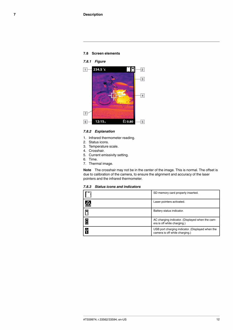
7.8 Screen elements
7.8.1 Figure
7.8.2 Explanation
1. Infrared thermometer reading.2. Status icons.3. Temperature scale.4. Crosshair.5. Current emissivity setting.6. Time.7. Thermal image.
Note The crosshair may not be in the center of the image. This is normal. The offset isdue to calibration of the camera, to ensure the alignment and accuracy of the laserpointers and the infrared thermometer.
7.8.3 Status icons and indicatorsSD memory card properly inserted.
Laser pointers activated.
Battery status indicator.
AC charging indicator. (Displayed when the cam-era is off while charging.)
USB port charging indicator. (Displayed when thecamera is off while charging.)
#T559974; r.33562/33594; en-US 12
Operation8
8.1 Charging the battery
When the icon is displayed, the battery requires a recharge.
Note The camera can be turned on and used while charging.
8.1.1 Charging the battery using the power supply
Follow this procedure:
1. Connect the power supply to a wall outlet.2. Connect the camera to the power supply using a USB cable.
8.1.2 Charging the battery using a computer
Follow this procedure:
1. Connect the camera to a computer using a USB cable.Note
• To charge the camera, the computer must be turned on.• Charging the camera using a USB cable connected to a computer takes consider-ably longer than using the FLIR power supply or the FLIR stand-alone batterycharger.
8.2 Turning on and turning off the camera
Follow this procedure:
1. Push and hold the button for more than 2 seconds to turn on/off the camera.
Note
• The Auto Power Off function automatically turns off the camera after a selectable peri-od of inactivity. For more information, see section 8.7.7 Auto Power Off, page 18.
• In the event that the camera screen freezes or “locks up”, push and hold the but-ton and at the same time push and hold the button for 10 seconds. This resetsand turns off the camera.
8.3 Measuring temperatures
8.3.1 General
The crosshair and the two laser pointers are used as targeting pointers for infrared tem-perature measurements. The crosshair indicates the center of the spot that the infraredthermometer is sensing. The object of interest should be framed by the two laserpointers.
Note
• For best results, temperature measurements should not be taken closer than 10″(25.4 cm).
• The crosshair may not be in the center of the image. This is normal. The offset is dueto calibration of the camera, to ensure the alignment and accuracy of the laserpointers and the infrared thermometer.
8.3.2 Procedure
Follow this procedure:
1. Aim the camera toward the area under test.2. Pull and hold the trigger. This activates the two laser pointers.3. Move the camera until only the object of interest is between the laser pointer spots.4. The measured temperature is displayed on the camera screen.
Note If the temperature exceeds the measurement temperature range of the cam-era, OL is displayed on the screen.
#T559974; r.33562/33594; en-US 13
Operation8
8.4 Saving an image
8.4.1 General
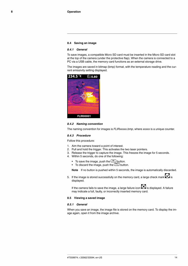
To save images, a compatible Micro SD card must be inserted in the Micro SD card slotat the top of the camera (under the protective flap). When the camera is connected to aPC via a USB cable, the memory card functions as an external storage drive.
The images are saved in bitmap (bmp) format, with the temperature reading and the cur-rent emissivity setting displayed.
8.4.2 Naming convention
The naming convention for images is FLIRxxxxx.bmp, where xxxxx is a unique counter.
8.4.3 Procedure
Follow this procedure:
1. Aim the camera toward a point of interest.2. Pull and hold the trigger. This activates the two laser pointers.3. Release the trigger to capture the image. This freezes the image for 5 seconds.4. Within 5 seconds, do one of the following:
• To save the image, push the button.• To discard the image, push the button.
Note If no button is pushed within 5 seconds, the image is automatically discarded.
5. If the image is stored successfully on the memory card, a large check mark isdisplayed.
If the camera fails to save the image, a large failure icon is displayed. A failuremay indicate a full, faulty, or incorrectly inserted memory card.
8.5 Viewing a saved image
8.5.1 General
When you save an image, the image file is stored on the memory card. To display the im-age again, open it from the image archive.
#T559974; r.33562/33594; en-US 14
Operation8
8.5.2 Procedure
Follow this procedure:
1. To open the image archive, do one of the following:
• Push the button for 4 seconds.
• Push the button to open the Settings menu. Select the icon and push the
button. Select the icon and push the button.
2. Use the buttons to scroll through the saved images.3. To close the image archive, push the button.
8.6 Deleting all images
8.6.1 General
You can delete all image files from the memory card.
Note You can also delete one or more images when the camera is connected to a com-puter via a USB cable. The memory card then functions as an external storage drive.
8.6.2 Procedure
Follow this procedure:
1. Push the button to display the Settings menu.
2. Select the icon and push the button.
3. Select the icon and push the button.4. Do one of the following:
• Select the icon by pushing the button to delete all images.Note This will reformat and delete all data from the memory card.
• Select the icon by pushing the button to cancel the delete action.
5. The icon is displayed for about 20 seconds while the card is being reformatted.6. Push the button to exit the Settings menu.
8.7 Changing the settings
8.7.1 General
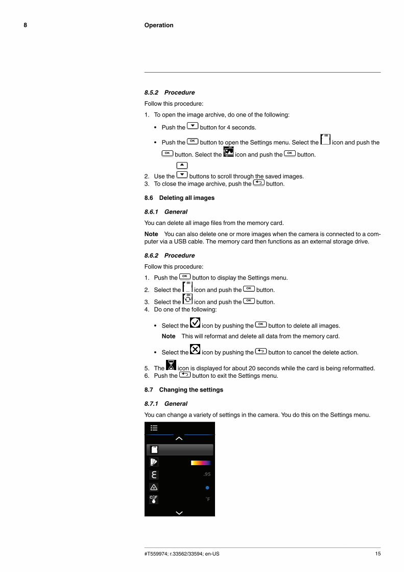
You can change a variety of settings in the camera. You do this on the Settings menu.
#T559974; r.33562/33594; en-US 15
Operation8
8.7.2 Palette
8.7.2.1 General
You can change the palette that the camera uses to display different temperatures.
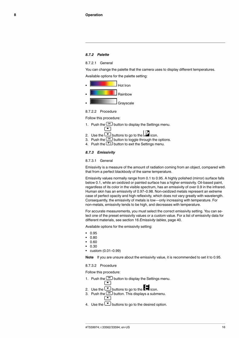
Available options for the palette setting:
• Hot Iron
• Rainbow
• Grayscale
8.7.2.2 Procedure
Follow this procedure:
1. Push the button to display the Settings menu.
2. Use the buttons to go to the icon.3. Push the button to toggle through the options.4. Push the button to exit the Settings menu.
8.7.3 Emissivity
8.7.3.1 General
Emissivity is a measure of the amount of radiation coming from an object, compared withthat from a perfect blackbody of the same temperature.
Emissivity values normally range from 0.1 to 0.95. A highly polished (mirror) surface fallsbelow 0.1, while an oxidized or painted surface has a higher emissivity. Oil-based paint,regardless of its color in the visible spectrum, has an emissivity of over 0.9 in the infrared.Human skin has an emissivity of 0.97–0.98. Non-oxidized metals represent an extremecase of perfect opacity and high reflexivity, which does not vary greatly with wavelength.Consequently, the emissivity of metals is low—only increasing with temperature. Fornon-metals, emissivity tends to be high, and decreases with temperature.
For accurate measurements, you must select the correct emissivity setting. You can se-lect one of the preset emissivity values or a custom value. For a list of emissivity data fordifferent materials, see section 16 Emissivity tables, page 40.
Available options for the emissivity setting:
• 0.95• 0.80• 0.60• 0.30• custom (0.01–0.99)
Note If you are unsure about the emissivity value, it is recommended to set it to 0.95.
8.7.3.2 Procedure
Follow this procedure:
1. Push the button to display the Settings menu.
2. Use the buttons to go to the icon.3. Push the button. This displays a submenu.
4. Use the buttons to go to the desired option.
#T559974; r.33562/33594; en-US 16
Operation8
5. With one of the preset options selected, do the following:
5.1. Push the button to save the setting and return to the Settings menu.
6. With the custom option selected, do the following:
6.1. Push the button to activate the custom field.
6.2. Use the buttons to adjust the emissivity factor.6.3. Push the button to inactivate the custom field.6.4. Push the button to return to the Settings menu.
7. Push the button to exit the Settings menu.
8.7.4 Laser pointer
8.7.4.1 General
The laser pointers are used as targeting pointers when measuring the temperature.
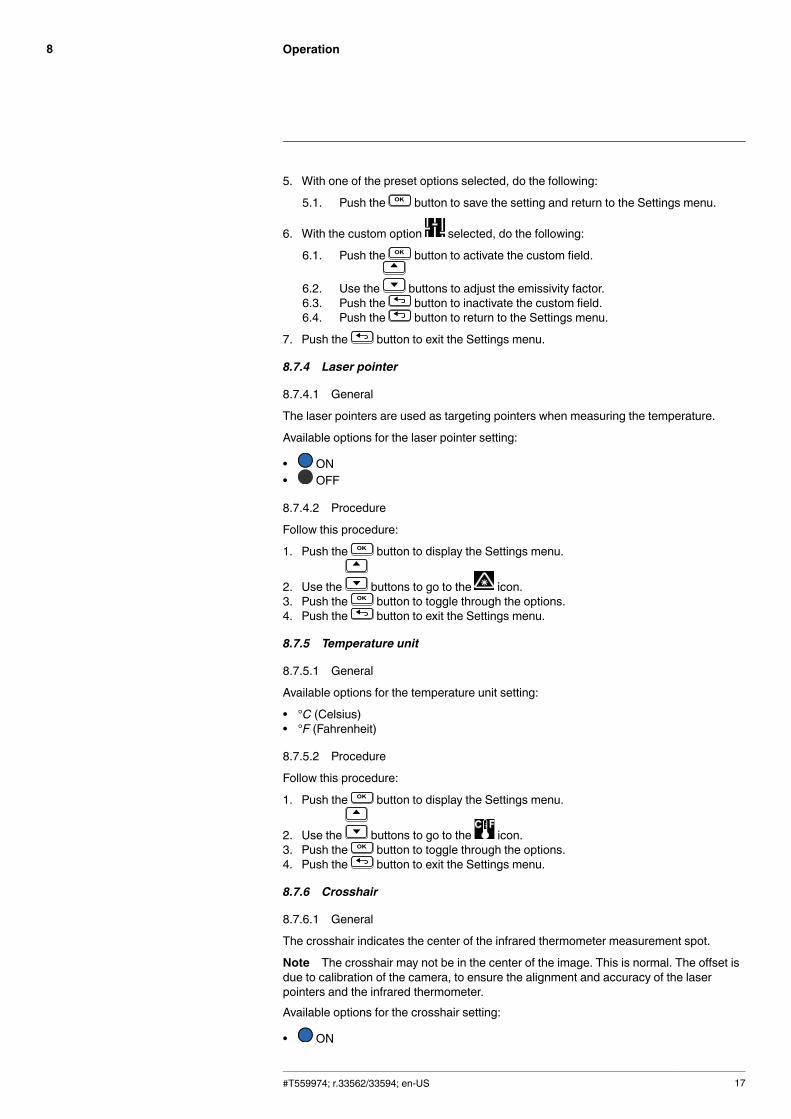
Available options for the laser pointer setting:
• ON• OFF
8.7.4.2 Procedure
Follow this procedure:
1. Push the button to display the Settings menu.
2. Use the buttons to go to the icon.3. Push the button to toggle through the options.4. Push the button to exit the Settings menu.
8.7.5 Temperature unit
8.7.5.1 General
Available options for the temperature unit setting:
• °C (Celsius)• °F (Fahrenheit)
8.7.5.2 Procedure
Follow this procedure:
1. Push the button to display the Settings menu.
2. Use the buttons to go to the icon.3. Push the button to toggle through the options.4. Push the button to exit the Settings menu.
8.7.6 Crosshair
8.7.6.1 General
The crosshair indicates the center of the infrared thermometer measurement spot.
Note The crosshair may not be in the center of the image. This is normal. The offset isdue to calibration of the camera, to ensure the alignment and accuracy of the laserpointers and the infrared thermometer.Available options for the crosshair setting:
• ON
#T559974; r.33562/33594; en-US 17
Operation8
• OFF
8.7.6.2 Procedure
Follow this procedure:
1. Push the button to display the Settings menu.
2. Use the buttons to go to the icon.3. Push the button to toggle through the options.4. Push the button to exit the Settings menu.
8.7.7 Auto Power Off
8.7.7.1 General
The Auto Power Off function automatically turns off the camera after a selectable periodof inactivity.
Available options for the Auto Power Off setting:
• OFF (the camera will not turn off automatically)• 1 m (1 minute)• 2 m (2 minutes)• 5 m (5 minutes)• 10 m (10 minutes)
8.7.7.2 Procedure
Follow this procedure:
1. Push the button to display the Settings menu.
2. Use the buttons to go to the icon.3. Push the button. This displays a submenu.
4. Use the buttons to go to the desired setting.5. Push the button to save the setting and return to the Settings menu.6. Push the button to exit the Settings menu.
8.7.8 Date and time
8.7.8.1 General
You can set the date and time. You can also select the time format setting.
Available options for the time format setting:
• 24 hour• 12 hour (AM/PM)
8.7.8.2 Procedure
Follow this procedure:
1. Push the button to display the Settings menu.
2. Use the buttons to go to the icon.3. Push the button. This displays a submenu.
4. Use the buttons to go to the desired setting.
#T559974; r.33562/33594; en-US 18
Operation8
5. With the date or time row selected, do the following:
5.1. Push the button to toggle through the fields.
5.2. Use the buttons to adjust the highlighted field.5.3. When the current row is finished, push the button to deselect all fields.
6. With the time format row selected, do the following:
6.1. Push the button to toggle through the options.
7. Push the button to return to the Settings menu.8. Push the button to exit the Settings menu.
8.7.9 Firmware information and calibration date
8.7.9.1 General
You can view the current firmware version and the calibration date.
To take advantage of our latest camera firmware, it is important that you keep your cam-era updated. For firmware updates, contact FLIR customer support.
The camera is calibrated at the factory prior to shipment. The camera is not serviceablein the field, and should be calibrated only by qualified FLIR Systems personnel. If calibra-tion is required, contact FLIR customer support.
For more information, see section 4 Customer help, page 5.
Available information:
• Firmware version
• Calibration date
8.7.9.2 Procedure
Follow this procedure:
1. Push the button to display the Settings menu.
2. Use the buttons to go to the icon.3. Push the button. This displays information about the firmware version and the
calibration date.4. Push the button to return to the Settings menu.5. Push the button to exit the Settings menu.
#T559974; r.33562/33594; en-US 19

Technical data9
9.1 Note about technical data
FLIR Systems reserves the right to change specifications at any time without prior notice.Please check http://support.flir.com for latest changes.
9.2 Note about authoritative versions
The authoritative version of this publication is English. In the event of divergences due totranslation errors, the English text has precedence.
Any late changes are first implemented in English.
#T559974; r.33562/33594; en-US 20
Technical data9
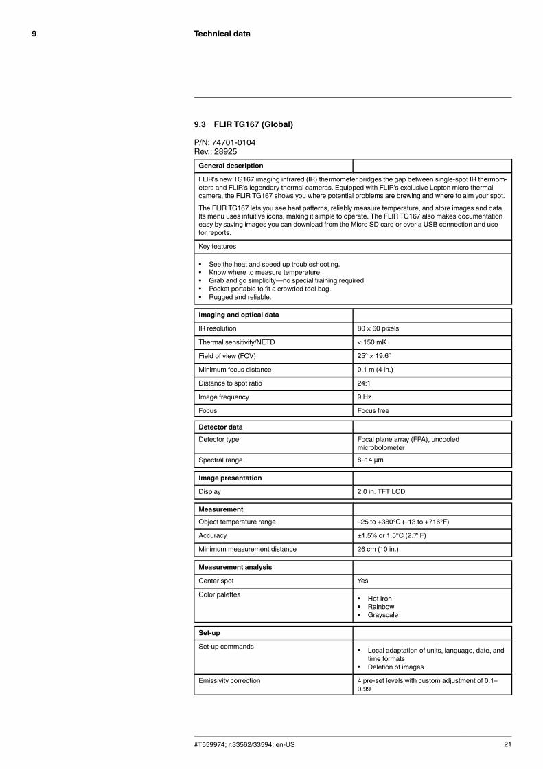
9.3 FLIR TG167 (Global)
P/N: 74701-0104Rev.: 28925General description
FLIR’s new TG167 imaging infrared (IR) thermometer bridges the gap between single-spot IR thermom-eters and FLIR’s legendary thermal cameras. Equipped with FLIR’s exclusive Lepton micro thermalcamera, the FLIR TG167 shows you where potential problems are brewing and where to aim your spot.
The FLIR TG167 lets you see heat patterns, reliably measure temperature, and store images and data.Its menu uses intuitive icons, making it simple to operate. The FLIR TG167 also makes documentationeasy by saving images you can download from the Micro SD card or over a USB connection and usefor reports.
Key features
• See the heat and speed up troubleshooting.• Know where to measure temperature.• Grab and go simplicity—no special training required.• Pocket portable to fit a crowded tool bag.• Rugged and reliable.
Imaging and optical data
IR resolution 80 × 60 pixels
Thermal sensitivity/NETD < 150 mK
Field of view (FOV) 25° × 19.6°
Minimum focus distance 0.1 m (4 in.)
Distance to spot ratio 24:1
Image frequency 9 Hz
Focus Focus free
Detector data
Detector type Focal plane array (FPA), uncooledmicrobolometer
Spectral range 8–14 μm
Image presentation
Display 2.0 in. TFT LCD
Measurement
Object temperature range –25 to +380°C (–13 to +716°F)
Accuracy ±1.5% or 1.5°C (2.7°F)
Minimum measurement distance 26 cm (10 in.)
Measurement analysis
Center spot Yes
Color palettes • Hot Iron• Rainbow• Grayscale
Set-up
Set-up commands • Local adaptation of units, language, date, andtime formats
• Deletion of images
Emissivity correction 4 pre-set levels with custom adjustment of 0.1–0.99
#T559974; r.33562/33594; en-US 21
Technical data9
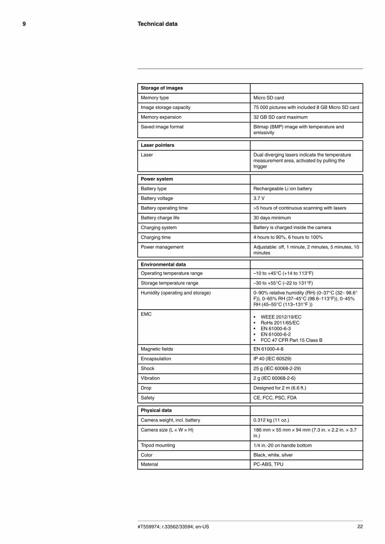
Storage of images
Memory type Micro SD card
Image storage capacity 75 000 pictures with included 8 GB Micro SD card
Memory expansion 32 GB SD card maximum
Saved image format Bitmap (BMP) image with temperature andemissivity
Laser pointers
Laser Dual diverging lasers indicate the temperaturemeasurement area, activated by pulling thetrigger
Power system
Battery type Rechargeable Li ion battery
Battery voltage 3.7 V
Battery operating time >5 hours of continuous scanning with lasers
Battery charge life 30 days minimum
Charging system Battery is charged inside the camera
Charging time 4 hours to 90%, 6 hours to 100%
Power management Adjustable: off, 1 minute, 2 minutes, 5 minutes, 10minutes
Environmental data
Operating temperature range –10 to +45°C (+14 to 113°F)
Storage temperature range –30 to +55°C (–22 to 131°F)
Humidity (operating and storage) 0–90% relative humidity (RH) (0–37°C (32– 98.6°F)), 0–65% RH (37–45°C (98.6–113°F)), 0–45%RH (45–55°C (113–131°F ))
EMC • WEEE 2012/19/EC• RoHs 2011/65/EC• EN 61000-6-3• EN 61000-6-2• FCC 47 CFR Part 15 Class B
Magnetic fields EN 61000-4-8
Encapsulation IP 40 (IEC 60529)
Shock 25 g (IEC 60068-2-29)
Vibration 2 g (IEC 60068-2-6)
Drop Designed for 2 m (6.6 ft.)
Safety CE, FCC, PSC, FDA
Physical data
Camera weight, incl. battery 0.312 kg (11 oz.)
Camera size (L × W × H) 186 mm × 55 mm × 94 mm (7.3 in. × 2.2 in. × 3.7in.)
Tripod mounting 1/4 in.-20 on handle bottom
Color Black, white, silver
Material PC-ABS, TPU
#T559974; r.33562/33594; en-US 22
Technical data9
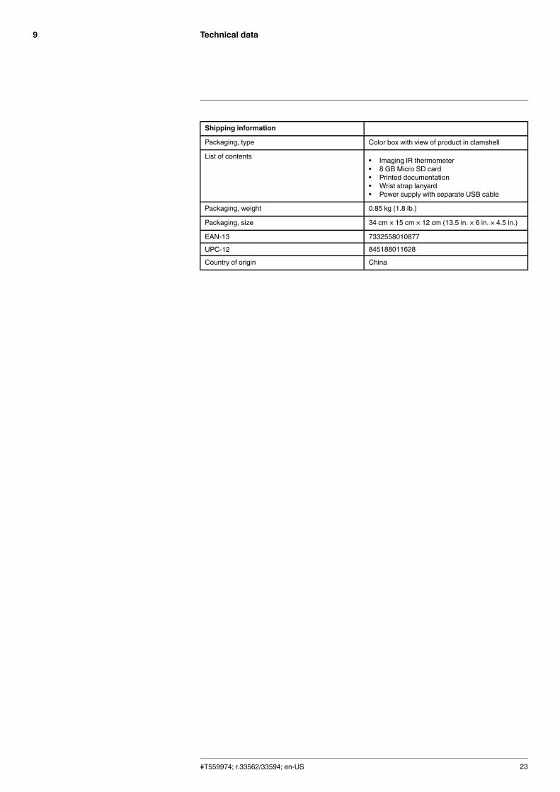
Shipping information
Packaging, type Color box with view of product in clamshell
List of contents • Imaging IR thermometer• 8 GB Micro SD card• Printed documentation• Wrist strap lanyard• Power supply with separate USB cable
Packaging, weight 0.85 kg (1.8 lb.)
Packaging, size 34 cm × 15 cm × 12 cm (13.5 in. × 6 in. × 4.5 in.)
EAN-13 7332558010877
UPC-12 845188011628
Country of origin China
#T559974; r.33562/33594; en-US 23

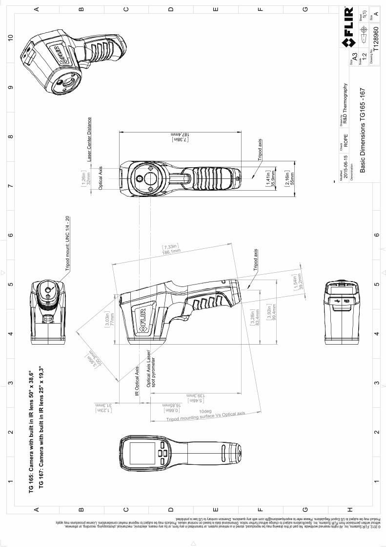
Mechanical drawings10
#T559974; r.33562/33594; en-US 24
3,
92in
99,4
mm
7,33in
186,1mm
3,
03in
77m
m
3,95in
100,3
mm
1,23in
31,3mm 0,66in
16,85mm
5,48in
139,3mm
1,54
in39
,2m
m
10deg
Tripod mounting surface Vs Optical axis
3,
28in
83,4
mm
IR O
ptic
al A
xis
Opt
ical
Axi
s La
ser/
spot
pyr
omet
er
Trip
od a
xis
1,
26in
32m
m
7,38in
187,4mm
1,
41in
35,9
mm
2,
16in
55m
m
Opt
ical
Axi
s
Trip
od a
xis
Trip
od m
ount
: UN
C 1
/4 -
20
Lase
r Cen
ter D
ista
nce
TG 1
65: C
amer
a w
ith b
uilt
in IR
lens
50°
x 3
8,6°
TG 1
67: C
amer
a w
ith b
uilt
in IR
lens
25°
x 1
9,3°
Shee
t
Dra
win
g N
o.
Size
Che
ckD
raw
n by
Den
omin
atio
nA3
1(1)
T128
960
Basi
c D
imen
sion
s TG
165
-167
RO
PE20
15-0
6-15
R&D
The
rmog
raph
yM
odifi
ed
12
34
56
78
910
A B C D E F G H
13
25
4
C FB D GEA
6Si
ze
A
1:2
Scal
e
© 2012, FLIR Systems, Inc. All rights reserved worldwide. No part of this drawing may be reproduced, stored in a retrieval system, or transmitted in any form, or by any means, electronic, mechanical, photocopying, recording, or otherwise, without written permission from FLIR Systems, Inc. Specifications subject to change without further notice. Dimensional data is based on nominal values. Products may be subject to regional market considerations. License procedures may apply. Product may be subject to US Export Regulations. Please refer to [email protected] with any questions. Diversion contrary to US law is prohibited.
-
Cleaning the camera11
11.1 Camera housing, cables, and other items
11.1.1 Liquids
Use one of these liquids:
• Warm water• A weak detergent solution
11.1.2 Equipment
A soft cloth
11.1.3 Procedure
Follow this procedure:
1. Soak the cloth in the liquid.2. Twist the cloth to remove excess liquid.3. Clean the part with the cloth.
CAUTION
Do not apply solvents or similar liquids to the camera, the cables, or other items. This can causedamage.
11.2 Infrared lens
11.2.1 Liquids
Use one of these liquids:
• A commercial lens cleaning liquid with more than 30% isopropyl alcohol.• 96% ethyl alcohol (C2H5OH).
11.2.2 Equipment
Cotton wool
11.2.3 Procedure
Follow this procedure:
1. Soak the cotton wool in the liquid.2. Twist the cotton wool to remove excess liquid.3. Clean the lens one time only and discard the cotton wool.
WARNING
Make sure that you read all applicable MSDS (Material Safety Data Sheets) and warning labels on con-tainers before you use a liquid: the liquids can be dangerous.
CAUTION
• Be careful when you clean the infrared lens. The lens has a delicate anti-reflective coating.• Do not clean the infrared lens too vigorously. This can damage the anti-reflective coating.
#T559974; r.33562/33594; en-US 26
Application examples12
12.1 Moisture & water damage
12.1.1 General
It is often possible to detect moisture and water damage in a house by using an infraredcamera. This is partly because the damaged area has a different heat conduction prop-erty and partly because it has a different thermal capacity to store heat than the sur-rounding material.
Many factors can come into play as to how moisture or water damage will appear in aninfrared image.
For example, heating and cooling of these parts takes place at different rates dependingon the material and the time of day. For this reason, it is important that other methods areused as well to check for moisture or water damage.
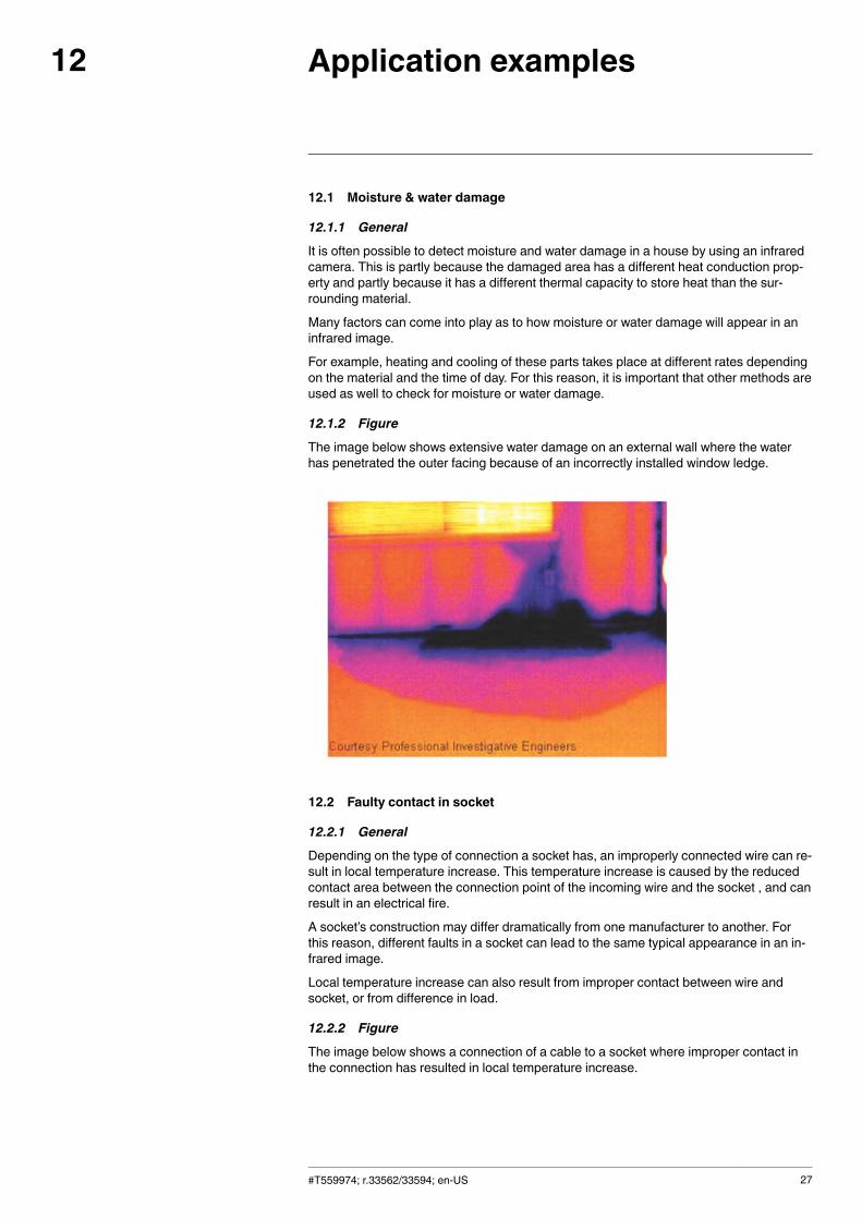
12.1.2 Figure
The image below shows extensive water damage on an external wall where the waterhas penetrated the outer facing because of an incorrectly installed window ledge.
12.2 Faulty contact in socket
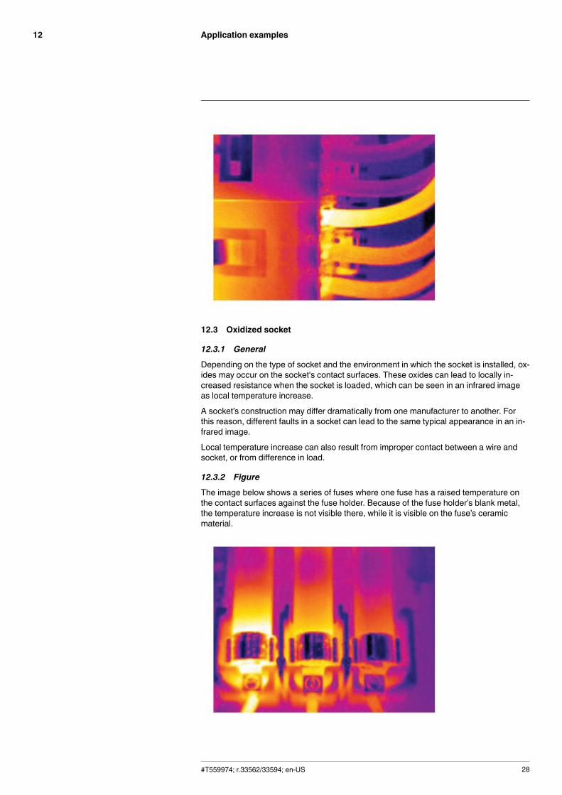
12.2.1 General
Depending on the type of connection a socket has, an improperly connected wire can re-sult in local temperature increase. This temperature increase is caused by the reducedcontact area between the connection point of the incoming wire and the socket , and canresult in an electrical fire.
A socket’s construction may differ dramatically from one manufacturer to another. Forthis reason, different faults in a socket can lead to the same typical appearance in an in-frared image.
Local temperature increase can also result from improper contact between wire andsocket, or from difference in load.
12.2.2 Figure
The image below shows a connection of a cable to a socket where improper contact inthe connection has resulted in local temperature increase.
#T559974; r.33562/33594; en-US 27
Application examples12
12.3 Oxidized socket
12.3.1 General
Depending on the type of socket and the environment in which the socket is installed, ox-ides may occur on the socket's contact surfaces. These oxides can lead to locally in-creased resistance when the socket is loaded, which can be seen in an infrared imageas local temperature increase.
A socket’s construction may differ dramatically from one manufacturer to another. Forthis reason, different faults in a socket can lead to the same typical appearance in an in-frared image.
Local temperature increase can also result from improper contact between a wire andsocket, or from difference in load.
12.3.2 Figure
The image below shows a series of fuses where one fuse has a raised temperature onthe contact surfaces against the fuse holder. Because of the fuse holder’s blank metal,the temperature increase is not visible there, while it is visible on the fuse’s ceramicmaterial.
#T559974; r.33562/33594; en-US 28
Application examples12
12.4 Insulation deficiencies
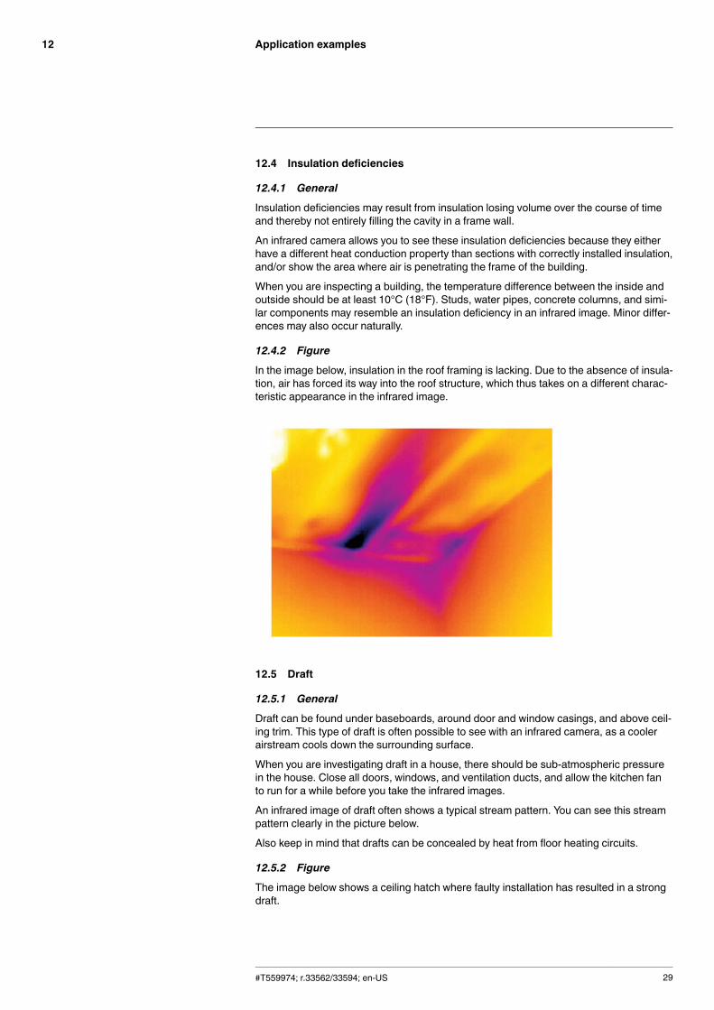
12.4.1 General
Insulation deficiencies may result from insulation losing volume over the course of timeand thereby not entirely filling the cavity in a frame wall.
An infrared camera allows you to see these insulation deficiencies because they eitherhave a different heat conduction property than sections with correctly installed insulation,and/or show the area where air is penetrating the frame of the building.
When you are inspecting a building, the temperature difference between the inside andoutside should be at least 10°C (18°F). Studs, water pipes, concrete columns, and simi-lar components may resemble an insulation deficiency in an infrared image. Minor differ-ences may also occur naturally.
12.4.2 Figure
In the image below, insulation in the roof framing is lacking. Due to the absence of insula-tion, air has forced its way into the roof structure, which thus takes on a different charac-teristic appearance in the infrared image.
12.5 Draft
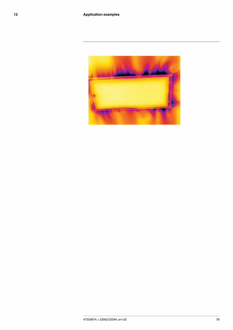
12.5.1 General
Draft can be found under baseboards, around door and window casings, and above ceil-ing trim. This type of draft is often possible to see with an infrared camera, as a coolerairstream cools down the surrounding surface.
When you are investigating draft in a house, there should be sub-atmospheric pressurein the house. Close all doors, windows, and ventilation ducts, and allow the kitchen fanto run for a while before you take the infrared images.
An infrared image of draft often shows a typical stream pattern. You can see this streampattern clearly in the picture below.
Also keep in mind that drafts can be concealed by heat from floor heating circuits.
12.5.2 Figure
The image below shows a ceiling hatch where faulty installation has resulted in a strongdraft.
#T559974; r.33562/33594; en-US 29
Application examples12
#T559974; r.33562/33594; en-US 30
About FLIR Systems13
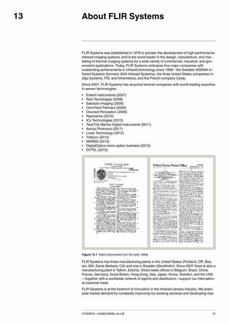
FLIR Systems was established in 1978 to pioneer the development of high-performanceinfrared imaging systems, and is the world leader in the design, manufacture, and mar-keting of thermal imaging systems for a wide variety of commercial, industrial, and gov-ernment applications. Today, FLIR Systems embraces five major companies withoutstanding achievements in infrared technology since 1958—the Swedish AGEMA In-frared Systems (formerly AGA Infrared Systems), the three United States companies In-digo Systems, FSI, and Inframetrics, and the French company Cedip.
Since 2007, FLIR Systems has acquired several companies with world-leading expertisein sensor technologies:
• Extech Instruments (2007)• Ifara Tecnologías (2008)• Salvador Imaging (2009)• OmniTech Partners (2009)• Directed Perception (2009)• Raymarine (2010)• ICx Technologies (2010)• TackTick Marine Digital Instruments (2011)• Aerius Photonics (2011)• Lorex Technology (2012)• Traficon (2012)• MARSS (2013)• DigitalOptics micro-optics business (2013)• DVTEL (2015)
Figure 13.1 Patent documents from the early 1960s
FLIR Systems has three manufacturing plants in the United States (Portland, OR, Bos-ton, MA, Santa Barbara, CA) and one in Sweden (Stockholm). Since 2007 there is also amanufacturing plant in Tallinn, Estonia. Direct sales offices in Belgium, Brazil, China,France, Germany, Great Britain, Hong Kong, Italy, Japan, Korea, Sweden, and the USA—together with a worldwide network of agents and distributors—support our internation-al customer base.
FLIR Systems is at the forefront of innovation in the infrared camera industry. We antici-pate market demand by constantly improving our existing cameras and developing new
#T559974; r.33562/33594; en-US 31
About FLIR Systems13
ones. The company has set milestones in product design and development such as theintroduction of the first battery-operated portable camera for industrial inspections, andthe first uncooled infrared camera, to mention just two innovations.
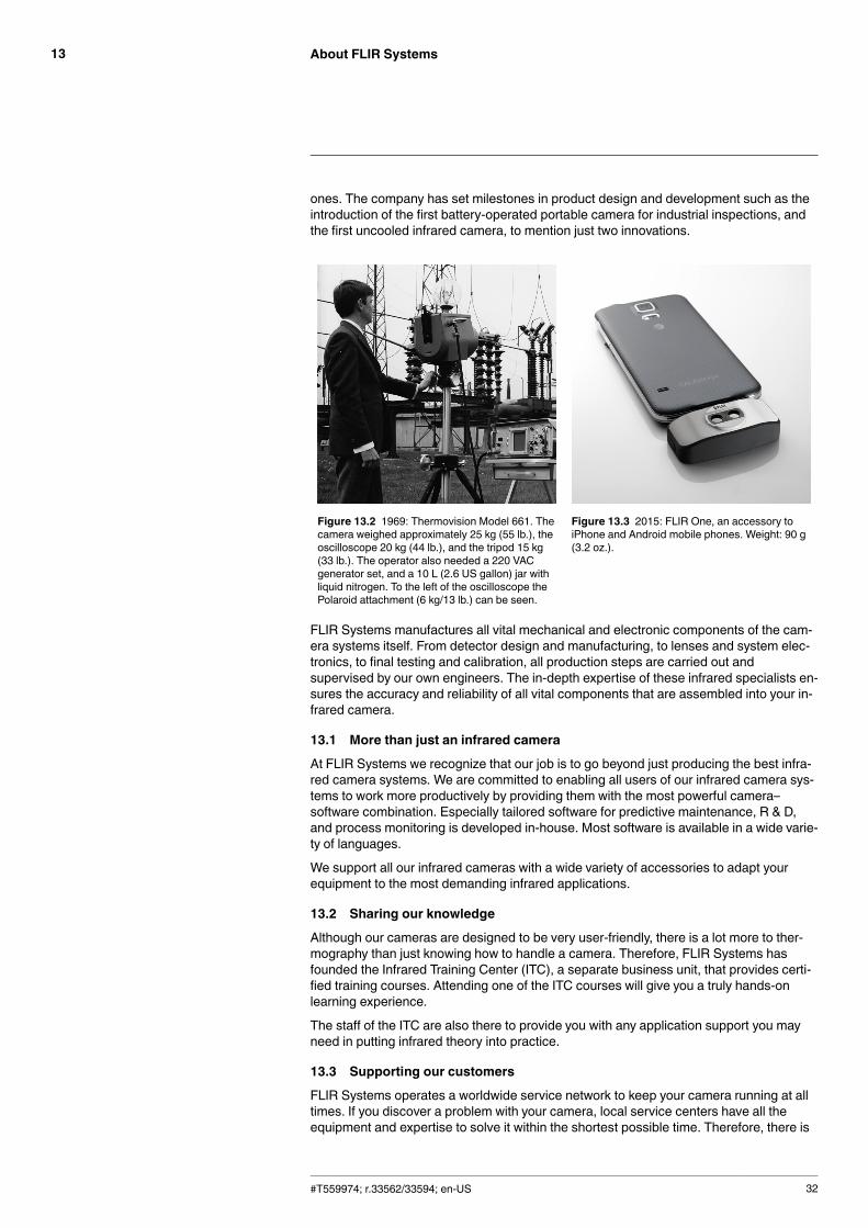
Figure 13.2 1969: Thermovision Model 661. Thecamera weighed approximately 25 kg (55 lb.), theoscilloscope 20 kg (44 lb.), and the tripod 15 kg(33 lb.). The operator also needed a 220 VACgenerator set, and a 10 L (2.6 US gallon) jar withliquid nitrogen. To the left of the oscilloscope thePolaroid attachment (6 kg/13 lb.) can be seen.
Figure 13.3 2015: FLIR One, an accessory toiPhone and Android mobile phones. Weight: 90 g(3.2 oz.).
FLIR Systems manufactures all vital mechanical and electronic components of the cam-era systems itself. From detector design and manufacturing, to lenses and system elec-tronics, to final testing and calibration, all production steps are carried out andsupervised by our own engineers. The in-depth expertise of these infrared specialists en-sures the accuracy and reliability of all vital components that are assembled into your in-frared camera.
13.1 More than just an infrared camera
At FLIR Systems we recognize that our job is to go beyond just producing the best infra-red camera systems. We are committed to enabling all users of our infrared camera sys-tems to work more productively by providing them with the most powerful camera–software combination. Especially tailored software for predictive maintenance, R & D,and process monitoring is developed in-house. Most software is available in a wide varie-ty of languages.
We support all our infrared cameras with a wide variety of accessories to adapt yourequipment to the most demanding infrared applications.
13.2 Sharing our knowledge
Although our cameras are designed to be very user-friendly, there is a lot more to ther-mography than just knowing how to handle a camera. Therefore, FLIR Systems hasfounded the Infrared Training Center (ITC), a separate business unit, that provides certi-fied training courses. Attending one of the ITC courses will give you a truly hands-onlearning experience.
The staff of the ITC are also there to provide you with any application support you mayneed in putting infrared theory into practice.
13.3 Supporting our customers
FLIR Systems operates a worldwide service network to keep your camera running at alltimes. If you discover a problem with your camera, local service centers have all theequipment and expertise to solve it within the shortest possible time. Therefore, there is
#T559974; r.33562/33594; en-US 32

About FLIR Systems13
no need to send your camera to the other side of the world or to talk to someone whodoes not speak your language.
#T559974; r.33562/33594; en-US 33
Glossary14
absorption(absorptionfactor)
The amount of radiation absorbed by an object relative to the re-ceived radiation. A number between 0 and 1.
atmosphere The gases between the object being measured and the camera, nor-mally air.
autoadjust A function making a camera perform an internal image correction.
autopalette The IR image is shown with an uneven spread of colors, displayingcold objects as well as hot ones at the same time.
blackbody Totally non-reflective object. All its radiation is due to its owntemperature.
blackbodyradiator
An IR radiating equipment with blackbody properties used to cali-brate IR cameras.
calculated at-mospherictransmission
A transmission value computed from the temperature, the relativehumidity of air and the distance to the object.
cavity radiator A bottle shaped radiator with an absorbing inside, viewed throughthe bottleneck.
colortemperature
The temperature for which the color of a blackbody matches a spe-cific color.
conduction The process that makes heat diffuse into a material.
continuousadjust
A function that adjusts the image. The function works all the time,continuously adjusting brightness and contrast according to the im-age content.
convection Convection is a heat transfer mode where a fluid is brought into mo-tion, either by gravity or another force, thereby transferring heat fromone place to another.
dual isotherm An isotherm with two color bands, instead of one.emissivity(emissivityfactor)
The amount of radiation coming from an object, compared to that ofa blackbody. A number between 0 and 1.
emittance Amount of energy emitted from an object per unit of time and area(W/m2)
environment Objects and gases that emit radiation towards the object beingmeasured.
estimated at-mospherictransmission
A transmission value, supplied by a user, replacing a calculated one
external optics Extra lenses, filters, heat shields etc. that can be put between thecamera and the object being measured.
filter A material transparent only to some of the infrared wavelengths.
FOV Field of view: The horizontal angle that can be viewed through an IRlens.
FPA Focal plane array: A type of IR detector.
graybody An object that emits a fixed fraction of the amount of energy of ablackbody for each wavelength.
IFOV Instantaneous field of view: A measure of the geometrical resolutionof an IR camera.
#T559974; r.33562/33594; en-US 34
Glossary14
image correc-tion (internal orexternal)
A way of compensating for sensitivity differences in various parts oflive images and also of stabilizing the camera.
infrared Non-visible radiation, having a wavelength from about 2–13 μm.
IR infraredisotherm A function highlighting those parts of an image that fall above, below
or between one or more temperature intervals.
isothermalcavity
A bottle-shaped radiator with a uniform temperature viewed throughthe bottleneck.
Laser LocatIR An electrically powered light source on the camera that emits laserradiation in a thin, concentrated beam to point at certain parts of theobject in front of the camera.
laser pointer An electrically powered light source on the camera that emits laserradiation in a thin, concentrated beam to point at certain parts of theobject in front of the camera.
level The center value of the temperature scale, usually expressed as asignal value.
manual adjust A way to adjust the image by manually changing certain parameters.
NETD Noise equivalent temperature difference. A measure of the imagenoise level of an IR camera.
noise Undesired small disturbance in the infrared image
objectparameters
A set of values describing the circumstances under which the meas-urement of an object was made, and the object itself (such as emis-sivity, reflected apparent temperature, distance etc.)
object signal A non-calibrated value related to the amount of radiation received bythe camera from the object.
palette The set of colors used to display an IR image.
pixel Stands for picture element. One single spot in an image.
radiance Amount of energy emitted from an object per unit of time, area andangle (W/m2/sr)
radiant power Amount of energy emitted from an object per unit of time (W)
radiation The process by which electromagnetic energy, is emitted by an ob-ject or a gas.
radiator A piece of IR radiating equipment.range The current overall temperature measurement limitation of an IR
camera. Cameras can have several ranges. Expressed as twoblackbody temperatures that limit the current calibration.
referencetemperature
A temperature which the ordinary measured values can be com-pared with.
reflection The amount of radiation reflected by an object relative to the re-ceived radiation. A number between 0 and 1.
relativehumidity
Relative humidity represents the ratio between the current water va-pour mass in the air and the maximum it may contain in saturationconditions.
saturationcolor
The areas that contain temperatures outside the present level/spansettings are colored with the saturation colors. The saturation colorscontain an ‘overflow’ color and an ‘underflow’ color. There is also athird red saturation color that marks everything saturated by the de-tector indicating that the range should probably be changed.
#T559974; r.33562/33594; en-US 35
Glossary14
span The interval of the temperature scale, usually expressed as a signalvalue.
spectral (radi-ant) emittance
Amount of energy emitted from an object per unit of time, area andwavelength (W/m2/μm)
temperaturedifference, ordifference oftemperature.
A value which is the result of a subtraction between two temperaturevalues.
temperaturerange
The current overall temperature measurement limitation of an IRcamera. Cameras can have several ranges. Expressed as twoblackbody temperatures that limit the current calibration.
temperaturescale
The way in which an IR image currently is displayed. Expressed astwo temperature values limiting the colors.
thermogram infrared image
transmission(or transmit-tance) factor
Gases and materials can be more or less transparent. Transmissionis the amount of IR radiation passing through them. A number be-tween 0 and 1.
transparentisotherm
An isotherm showing a linear spread of colors, instead of coveringthe highlighted parts of the image.
visual Refers to the video mode of a IR camera, as opposed to the normal,thermographic mode. When a camera is in video mode it capturesordinary video images, while thermographic images are capturedwhen the camera is in IR mode.
#T559974; r.33562/33594; en-US 36
History of infrared technology15
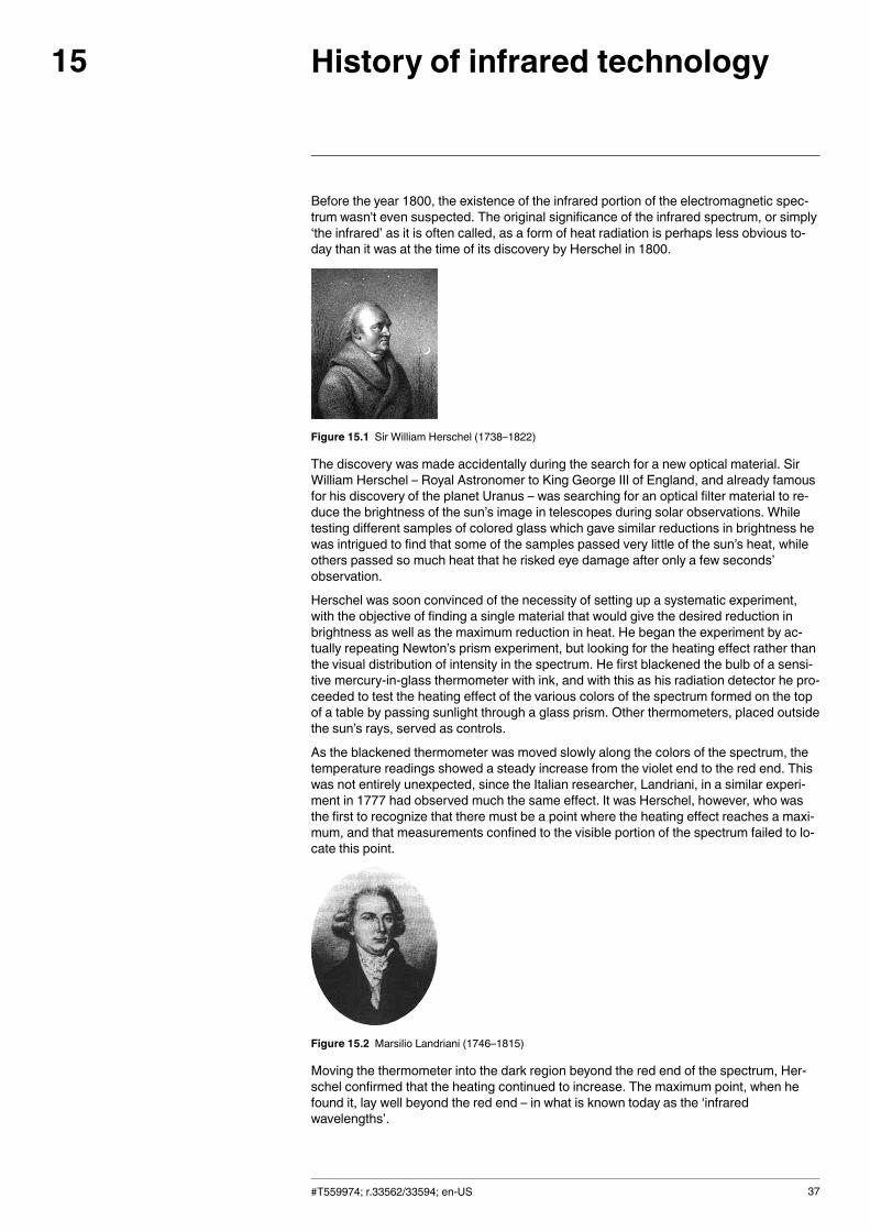
Before the year 1800, the existence of the infrared portion of the electromagnetic spec-trum wasn't even suspected. The original significance of the infrared spectrum, or simply‘the infrared’ as it is often called, as a form of heat radiation is perhaps less obvious to-day than it was at the time of its discovery by Herschel in 1800.
Figure 15.1 Sir William Herschel (1738–1822)
The discovery was made accidentally during the search for a new optical material. SirWilliam Herschel – Royal Astronomer to King George III of England, and already famousfor his discovery of the planet Uranus – was searching for an optical filter material to re-duce the brightness of the sun’s image in telescopes during solar observations. Whiletesting different samples of colored glass which gave similar reductions in brightness hewas intrigued to find that some of the samples passed very little of the sun’s heat, whileothers passed so much heat that he risked eye damage after only a few seconds’observation.
Herschel was soon convinced of the necessity of setting up a systematic experiment,with the objective of finding a single material that would give the desired reduction inbrightness as well as the maximum reduction in heat. He began the experiment by ac-tually repeating Newton’s prism experiment, but looking for the heating effect rather thanthe visual distribution of intensity in the spectrum. He first blackened the bulb of a sensi-tive mercury-in-glass thermometer with ink, and with this as his radiation detector he pro-ceeded to test the heating effect of the various colors of the spectrum formed on the topof a table by passing sunlight through a glass prism. Other thermometers, placed outsidethe sun’s rays, served as controls.
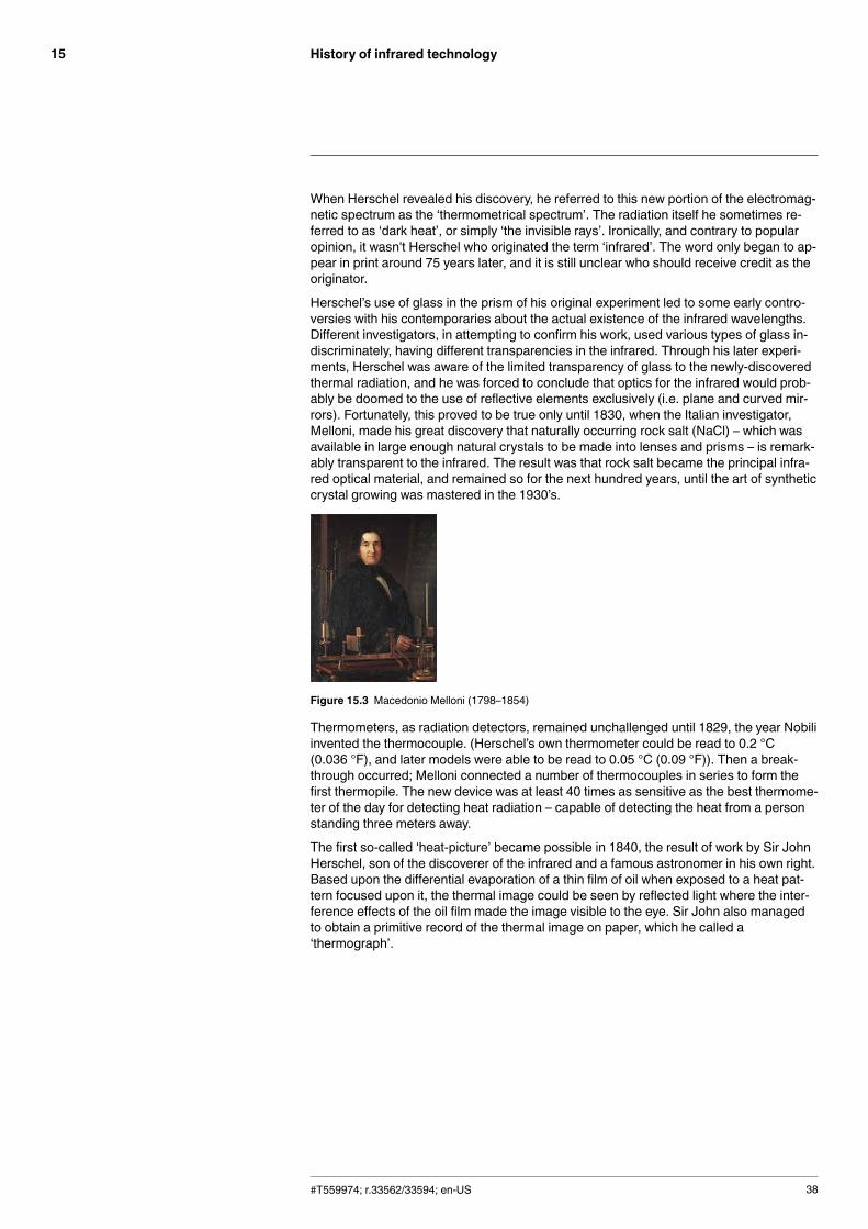
As the blackened thermometer was moved slowly along the colors of the spectrum, thetemperature readings showed a steady increase from the violet end to the red end. Thiswas not entirely unexpected, since the Italian researcher, Landriani, in a similar experi-ment in 1777 had observed much the same effect. It was Herschel, however, who wasthe first to recognize that there must be a point where the heating effect reaches a maxi-mum, and that measurements confined to the visible portion of the spectrum failed to lo-cate this point.
Figure 15.2 Marsilio Landriani (1746–1815)
Moving the thermometer into the dark region beyond the red end of the spectrum, Her-schel confirmed that the heating continued to increase. The maximum point, when hefound it, lay well beyond the red end – in what is known today as the ‘infraredwavelengths’.
#T559974; r.33562/33594; en-US 37
History of infrared technology15
When Herschel revealed his discovery, he referred to this new portion of the electromag-netic spectrum as the ‘thermometrical spectrum’. The radiation itself he sometimes re-ferred to as ‘dark heat’, or simply ‘the invisible rays’. Ironically, and contrary to popularopinion, it wasn't Herschel who originated the term ‘infrared’. The word only began to ap-pear in print around 75 years later, and it is still unclear who should receive credit as theoriginator.
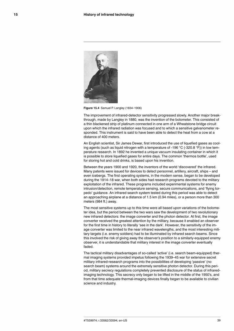
Herschel’s use of glass in the prism of his original experiment led to some early contro-versies with his contemporaries about the actual existence of the infrared wavelengths.Different investigators, in attempting to confirm his work, used various types of glass in-discriminately, having different transparencies in the infrared. Through his later experi-ments, Herschel was aware of the limited transparency of glass to the newly-discoveredthermal radiation, and he was forced to conclude that optics for the infrared would prob-ably be doomed to the use of reflective elements exclusively (i.e. plane and curved mir-rors). Fortunately, this proved to be true only until 1830, when the Italian investigator,Melloni, made his great discovery that naturally occurring rock salt (NaCl) – which wasavailable in large enough natural crystals to be made into lenses and prisms – is remark-ably transparent to the infrared. The result was that rock salt became the principal infra-red optical material, and remained so for the next hundred years, until the art of syntheticcrystal growing was mastered in the 1930’s.
Figure 15.3 Macedonio Melloni (1798–1854)
Thermometers, as radiation detectors, remained unchallenged until 1829, the year Nobiliinvented the thermocouple. (Herschel’s own thermometer could be read to 0.2 °C(0.036 °F), and later models were able to be read to 0.05 °C (0.09 °F)). Then a break-through occurred; Melloni connected a number of thermocouples in series to form thefirst thermopile. The new device was at least 40 times as sensitive as the best thermome-ter of the day for detecting heat radiation – capable of detecting the heat from a personstanding three meters away.
The first so-called ‘heat-picture’ became possible in 1840, the result of work by Sir JohnHerschel, son of the discoverer of the infrared and a famous astronomer in his own right.Based upon the differential evaporation of a thin film of oil when exposed to a heat pat-tern focused upon it, the thermal image could be seen by reflected light where the inter-ference effects of the oil film made the image visible to the eye. Sir John also managedto obtain a primitive record of the thermal image on paper, which he called a‘thermograph’.
#T559974; r.33562/33594; en-US 38
History of infrared technology15
Figure 15.4 Samuel P. Langley (1834–1906)
The improvement of infrared-detector sensitivity progressed slowly. Another major break-through, made by Langley in 1880, was the invention of the bolometer. This consisted ofa thin blackened strip of platinum connected in one arm of a Wheatstone bridge circuitupon which the infrared radiation was focused and to which a sensitive galvanometer re-sponded. This instrument is said to have been able to detect the heat from a cow at adistance of 400 meters.
An English scientist, Sir James Dewar, first introduced the use of liquefied gases as cool-ing agents (such as liquid nitrogen with a temperature of -196 °C (-320.8 °F)) in low tem-perature research. In 1892 he invented a unique vacuum insulating container in which itis possible to store liquefied gases for entire days. The common ‘thermos bottle’, usedfor storing hot and cold drinks, is based upon his invention.
Between the years 1900 and 1920, the inventors of the world ‘discovered’ the infrared.Many patents were issued for devices to detect personnel, artillery, aircraft, ships – andeven icebergs. The first operating systems, in the modern sense, began to be developedduring the 1914–18 war, when both sides had research programs devoted to the militaryexploitation of the infrared. These programs included experimental systems for enemyintrusion/detection, remote temperature sensing, secure communications, and ‘flying tor-pedo’ guidance. An infrared search system tested during this period was able to detectan approaching airplane at a distance of 1.5 km (0.94 miles), or a person more than 300meters (984 ft.) away.
The most sensitive systems up to this time were all based upon variations of the bolome-ter idea, but the period between the two wars saw the development of two revolutionarynew infrared detectors: the image converter and the photon detector. At first, the imageconverter received the greatest attention by the military, because it enabled an observerfor the first time in history to literally ‘see in the dark’. However, the sensitivity of the im-age converter was limited to the near infrared wavelengths, and the most interesting mili-tary targets (i.e. enemy soldiers) had to be illuminated by infrared search beams. Sincethis involved the risk of giving away the observer’s position to a similarly-equipped enemyobserver, it is understandable that military interest in the image converter eventuallyfaded.
The tactical military disadvantages of so-called 'active’ (i.e. search beam-equipped) ther-mal imaging systems provided impetus following the 1939–45 war for extensive secretmilitary infrared-research programs into the possibilities of developing ‘passive’ (nosearch beam) systems around the extremely sensitive photon detector. During this peri-od, military secrecy regulations completely prevented disclosure of the status of infrared-imaging technology. This secrecy only began to be lifted in the middle of the 1950’s, andfrom that time adequate thermal-imaging devices finally began to be available to civilianscience and industry.
#T559974; r.33562/33594; en-US 39
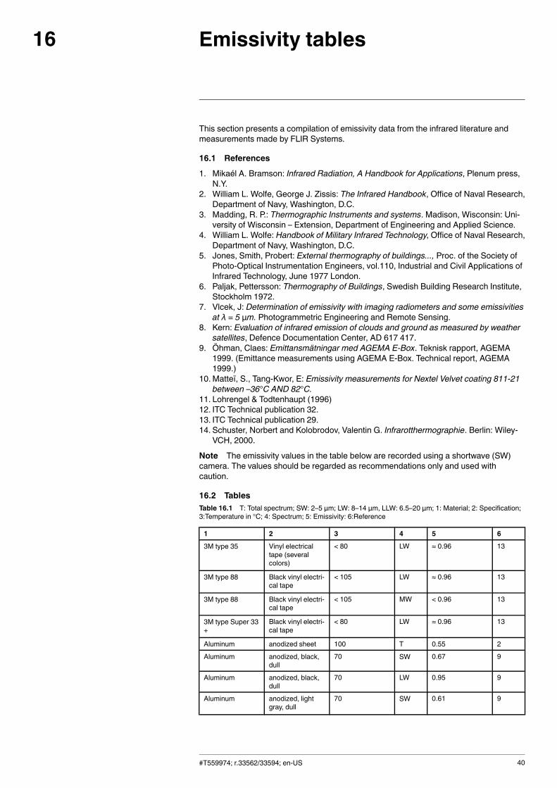
Emissivity tables16
This section presents a compilation of emissivity data from the infrared literature andmeasurements made by FLIR Systems.
16.1 References
1. Mikaél A. Bramson: Infrared Radiation, A Handbook for Applications, Plenum press,N.Y.
2. William L. Wolfe, George J. Zissis: The Infrared Handbook, Office of Naval Research,Department of Navy, Washington, D.C.
3. Madding, R. P.: Thermographic Instruments and systems. Madison, Wisconsin: Uni-versity of Wisconsin – Extension, Department of Engineering and Applied Science.
4. William L. Wolfe: Handbook of Military Infrared Technology, Office of Naval Research,Department of Navy, Washington, D.C.
5. Jones, Smith, Probert: External thermography of buildings..., Proc. of the Society ofPhoto-Optical Instrumentation Engineers, vol.110, Industrial and Civil Applications ofInfrared Technology, June 1977 London.
6. Paljak, Pettersson: Thermography of Buildings, Swedish Building Research Institute,Stockholm 1972.
7. Vlcek, J: Determination of emissivity with imaging radiometers and some emissivitiesat λ = 5 µm. Photogrammetric Engineering and Remote Sensing.
8. Kern: Evaluation of infrared emission of clouds and ground as measured by weathersatellites, Defence Documentation Center, AD 617 417.
9. Öhman, Claes: Emittansmätningar med AGEMA E-Box. Teknisk rapport, AGEMA1999. (Emittance measurements using AGEMA E-Box. Technical report, AGEMA1999.)
10. Matteï, S., Tang-Kwor, E: Emissivity measurements for Nextel Velvet coating 811-21between –36°C AND 82°C.
11. Lohrengel & Todtenhaupt (1996)12. ITC Technical publication 32.13. ITC Technical publication 29.14. Schuster, Norbert and Kolobrodov, Valentin G. Infrarotthermographie. Berlin: Wiley-
VCH, 2000.
Note The emissivity values in the table below are recorded using a shortwave (SW)camera. The values should be regarded as recommendations only and used withcaution.
16.2 TablesTable 16.1 T: Total spectrum; SW: 2–5 µm; LW: 8–14 µm, LLW: 6.5–20 µm; 1: Material; 2: Specification;3:Temperature in °C; 4: Spectrum; 5: Emissivity: 6:Reference
1 2 3 4 5 6
3M type 35 Vinyl electricaltape (severalcolors)
< 80 LW ≈ 0.96 13
3M type 88 Black vinyl electri-cal tape
< 105 LW ≈ 0.96 13
3M type 88 Black vinyl electri-cal tape
< 105 MW < 0.96 13
3M type Super 33+
Black vinyl electri-cal tape
< 80 LW ≈ 0.96 13
Aluminum anodized sheet 100 T 0.55 2
Aluminum anodized, black,dull
70 SW 0.67 9
Aluminum anodized, black,dull
70 LW 0.95 9
Aluminum anodized, lightgray, dull
70 SW 0.61 9
#T559974; r.33562/33594; en-US 40
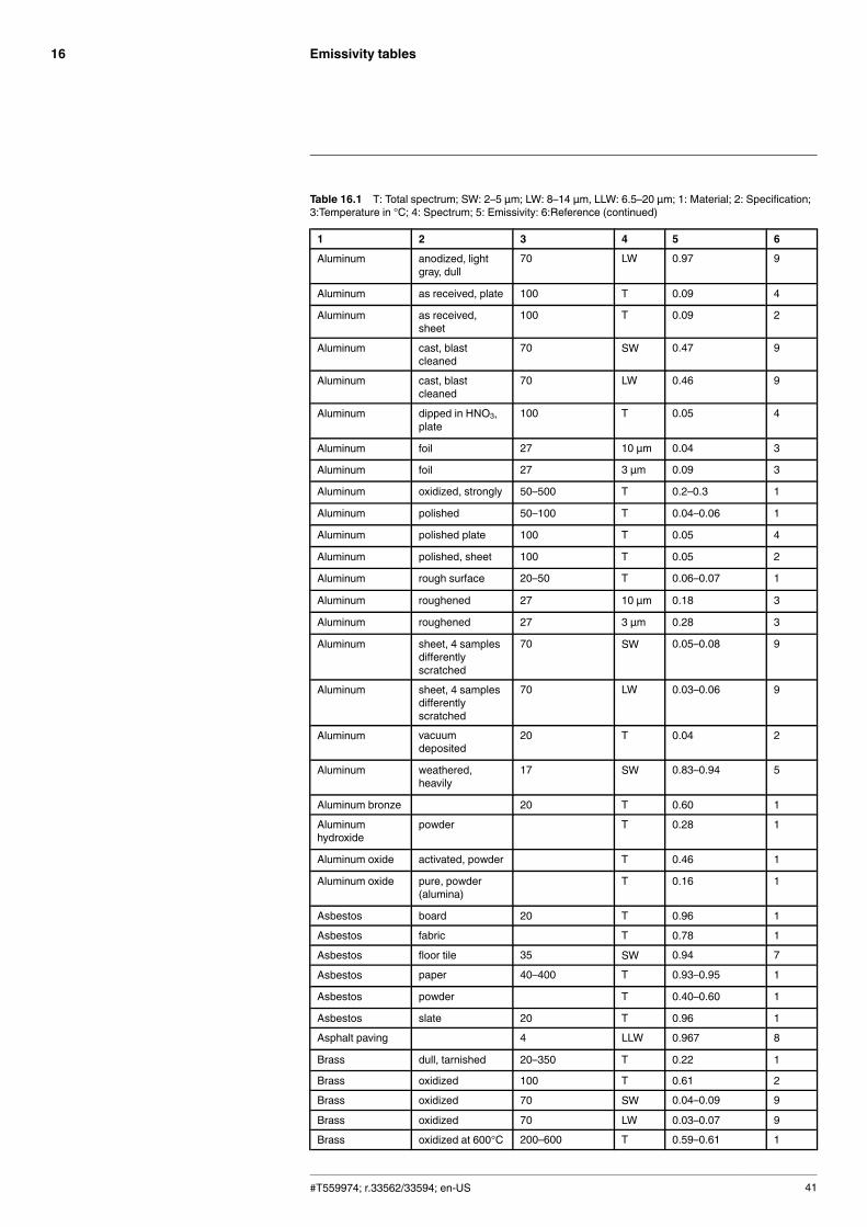
Emissivity tables16
Table 16.1 T: Total spectrum; SW: 2–5 µm; LW: 8–14 µm, LLW: 6.5–20 µm; 1: Material; 2: Specification;3:Temperature in °C; 4: Spectrum; 5: Emissivity: 6:Reference (continued)
1 2 3 4 5 6
Aluminum anodized, lightgray, dull
70 LW 0.97 9
Aluminum as received, plate 100 T 0.09 4
Aluminum as received,sheet
100 T 0.09 2
Aluminum cast, blastcleaned
70 SW 0.47 9
Aluminum cast, blastcleaned
70 LW 0.46 9
Aluminum dipped in HNO3,plate
100 T 0.05 4
Aluminum foil 27 10 µm 0.04 3
Aluminum foil 27 3 µm 0.09 3
Aluminum oxidized, strongly 50–500 T 0.2–0.3 1
Aluminum polished 50–100 T 0.04–0.06 1
Aluminum polished plate 100 T 0.05 4
Aluminum polished, sheet 100 T 0.05 2
Aluminum rough surface 20–50 T 0.06–0.07 1
Aluminum roughened 27 10 µm 0.18 3
Aluminum roughened 27 3 µm 0.28 3
Aluminum sheet, 4 samplesdifferentlyscratched
70 SW 0.05–0.08 9
Aluminum sheet, 4 samplesdifferentlyscratched
70 LW 0.03–0.06 9
Aluminum vacuumdeposited
20 T 0.04 2
Aluminum weathered,heavily
17 SW 0.83–0.94 5
Aluminum bronze 20 T 0.60 1
Aluminumhydroxide
powder T 0.28 1
Aluminum oxide activated, powder T 0.46 1
Aluminum oxide pure, powder(alumina)
T 0.16 1
Asbestos board 20 T 0.96 1
Asbestos fabric T 0.78 1
Asbestos floor tile 35 SW 0.94 7
Asbestos paper 40–400 T 0.93–0.95 1
Asbestos powder T 0.40–0.60 1
Asbestos slate 20 T 0.96 1
Asphalt paving 4 LLW 0.967 8
Brass dull, tarnished 20–350 T 0.22 1
Brass oxidized 100 T 0.61 2
Brass oxidized 70 SW 0.04–0.09 9
Brass oxidized 70 LW 0.03–0.07 9
Brass oxidized at 600°C 200–600 T 0.59–0.61 1
#T559974; r.33562/33594; en-US 41
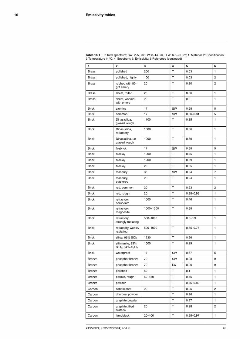
Emissivity tables16
Table 16.1 T: Total spectrum; SW: 2–5 µm; LW: 8–14 µm, LLW: 6.5–20 µm; 1: Material; 2: Specification;3:Temperature in °C; 4: Spectrum; 5: Emissivity: 6:Reference (continued)
1 2 3 4 5 6
Brass polished 200 T 0.03 1
Brass polished, highly 100 T 0.03 2
Brass rubbed with 80-grit emery
20 T 0.20 2
Brass sheet, rolled 20 T 0.06 1
Brass sheet, workedwith emery
20 T 0.2 1
Brick alumina 17 SW 0.68 5
Brick common 17 SW 0.86–0.81 5
Brick Dinas silica,glazed, rough
1100 T 0.85 1
Brick Dinas silica,refractory
1000 T 0.66 1
Brick Dinas silica, un-glazed, rough
1000 T 0.80 1
Brick firebrick 17 SW 0.68 5
Brick fireclay 1000 T 0.75 1
Brick fireclay 1200 T 0.59 1
Brick fireclay 20 T 0.85 1
Brick masonry 35 SW 0.94 7
Brick masonry,plastered
20 T 0.94 1
Brick red, common 20 T 0.93 2
Brick red, rough 20 T 0.88–0.93 1
Brick refractory,corundum
1000 T 0.46 1
Brick refractory,magnesite
1000–1300 T 0.38 1
Brick refractory,strongly radiating
500–1000 T 0.8–0.9 1
Brick refractory, weaklyradiating
500–1000 T 0.65–0.75 1
Brick silica, 95% SiO2 1230 T 0.66 1
Brick sillimanite, 33%SiO2, 64% Al2O3
1500 T 0.29 1
Brick waterproof 17 SW 0.87 5
Bronze phosphor bronze 70 SW 0.08 9
Bronze phosphor bronze 70 LW 0.06 9
Bronze polished 50 T 0.1 1
Bronze porous, rough 50–150 T 0.55 1
Bronze powder T 0.76–0.80 1
Carbon candle soot 20 T 0.95 2
Carbon charcoal powder T 0.96 1
Carbon graphite powder T 0.97 1
Carbon graphite, filedsurface
20 T 0.98 2
Carbon lampblack 20–400 T 0.95–0.97 1
#T559974; r.33562/33594; en-US 42
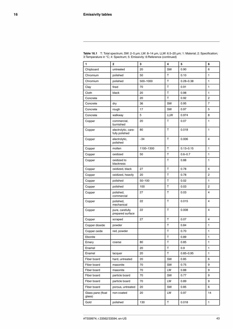
Emissivity tables16
Table 16.1 T: Total spectrum; SW: 2–5 µm; LW: 8–14 µm, LLW: 6.5–20 µm; 1: Material; 2: Specification;3:Temperature in °C; 4: Spectrum; 5: Emissivity: 6:Reference (continued)
1 2 3 4 5 6
Chipboard untreated 20 SW 0.90 6
Chromium polished 50 T 0.10 1
Chromium polished 500–1000 T 0.28–0.38 1
Clay fired 70 T 0.91 1
Cloth black 20 T 0.98 1
Concrete 20 T 0.92 2
Concrete dry 36 SW 0.95 7
Concrete rough 17 SW 0.97 5
Concrete walkway 5 LLW 0.974 8
Copper commercial,burnished
20 T 0.07 1
Copper electrolytic, care-fully polished
80 T 0.018 1
Copper electrolytic,polished
–34 T 0.006 4
Copper molten 1100–1300 T 0.13–0.15 1
Copper oxidized 50 T 0.6–0.7 1
Copper oxidized toblackness
T 0.88 1
Copper oxidized, black 27 T 0.78 4
Copper oxidized, heavily 20 T 0.78 2
Copper polished 50–100 T 0.02 1
Copper polished 100 T 0.03 2
Copper polished,commercial
27 T 0.03 4
Copper polished,mechanical
22 T 0.015 4
Copper pure, carefullyprepared surface
22 T 0.008 4
Copper scraped 27 T 0.07 4
Copper dioxide powder T 0.84 1
Copper oxide red, powder T 0.70 1
Ebonite T 0.89 1
Emery coarse 80 T 0.85 1
Enamel 20 T 0.9 1
Enamel lacquer 20 T 0.85–0.95 1
Fiber board hard, untreated 20 SW 0.85 6
Fiber board masonite 70 SW 0.75 9
Fiber board masonite 70 LW 0.88 9
Fiber board particle board 70 SW 0.77 9
Fiber board particle board 70 LW 0.89 9
Fiber board porous, untreated 20 SW 0.85 6
Glass pane (floatglass)
non-coated 20 LW 0.97 14
Gold polished 130 T 0.018 1
#T559974; r.33562/33594; en-US 43
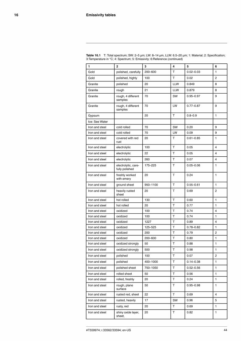
Emissivity tables16
Table 16.1 T: Total spectrum; SW: 2–5 µm; LW: 8–14 µm, LLW: 6.5–20 µm; 1: Material; 2: Specification;3:Temperature in °C; 4: Spectrum; 5: Emissivity: 6:Reference (continued)
1 2 3 4 5 6
Gold polished, carefully 200–600 T 0.02–0.03 1
Gold polished, highly 100 T 0.02 2
Granite polished 20 LLW 0.849 8
Granite rough 21 LLW 0.879 8
Granite rough, 4 differentsamples
70 SW 0.95–0.97 9
Granite rough, 4 differentsamples
70 LW 0.77–0.87 9
Gypsum 20 T 0.8–0.9 1
Ice: See Water
Iron and steel cold rolled 70 SW 0.20 9
Iron and steel cold rolled 70 LW 0.09 9
Iron and steel covered with redrust
20 T 0.61–0.85 1
Iron and steel electrolytic 100 T 0.05 4
Iron and steel electrolytic 22 T 0.05 4
Iron and steel electrolytic 260 T 0.07 4
Iron and steel electrolytic, care-fully polished
175–225 T 0.05–0.06 1
Iron and steel freshly workedwith emery
20 T 0.24 1
Iron and steel ground sheet 950–1100 T 0.55–0.61 1
Iron and steel heavily rustedsheet
20 T 0.69 2
Iron and steel hot rolled 130 T 0.60 1
Iron and steel hot rolled 20 T 0.77 1
Iron and steel oxidized 100 T 0.74 4
Iron and steel oxidized 100 T 0.74 1
Iron and steel oxidized 1227 T 0.89 4
Iron and steel oxidized 125–525 T 0.78–0.82 1
Iron and steel oxidized 200 T 0.79 2
Iron and steel oxidized 200–600 T 0.80 1
Iron and steel oxidized strongly 50 T 0.88 1
Iron and steel oxidized strongly 500 T 0.98 1
Iron and steel polished 100 T 0.07 2
Iron and steel polished 400–1000 T 0.14–0.38 1
Iron and steel polished sheet 750–1050 T 0.52–0.56 1
Iron and steel rolled sheet 50 T 0.56 1
Iron and steel rolled, freshly 20 T 0.24 1
Iron and steel rough, planesurface
50 T 0.95–0.98 1
Iron and steel rusted red, sheet 22 T 0.69 4
Iron and steel rusted, heavily 17 SW 0.96 5
Iron and steel rusty, red 20 T 0.69 1
Iron and steel shiny oxide layer,sheet,
20 T 0.82 1
#T559974; r.33562/33594; en-US 44
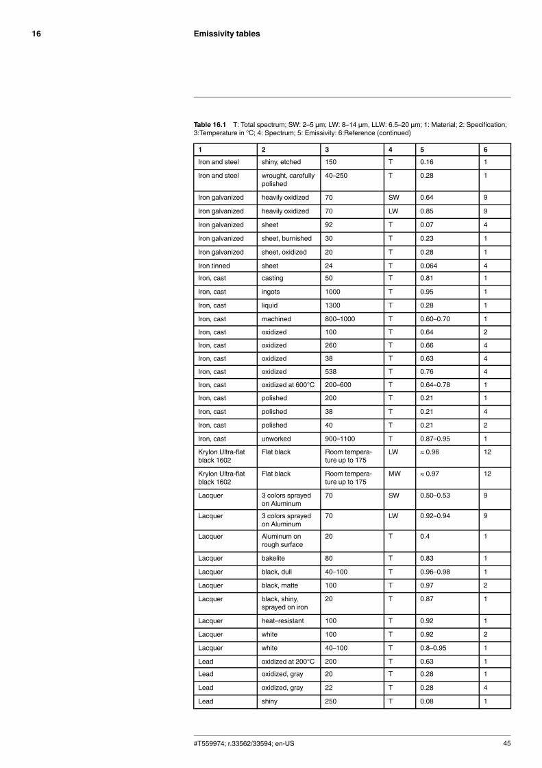
Emissivity tables16
Table 16.1 T: Total spectrum; SW: 2–5 µm; LW: 8–14 µm, LLW: 6.5–20 µm; 1: Material; 2: Specification;3:Temperature in °C; 4: Spectrum; 5: Emissivity: 6:Reference (continued)
1 2 3 4 5 6
Iron and steel shiny, etched 150 T 0.16 1
Iron and steel wrought, carefullypolished
40–250 T 0.28 1
Iron galvanized heavily oxidized 70 SW 0.64 9
Iron galvanized heavily oxidized 70 LW 0.85 9
Iron galvanized sheet 92 T 0.07 4
Iron galvanized sheet, burnished 30 T 0.23 1
Iron galvanized sheet, oxidized 20 T 0.28 1
Iron tinned sheet 24 T 0.064 4
Iron, cast casting 50 T 0.81 1
Iron, cast ingots 1000 T 0.95 1
Iron, cast liquid 1300 T 0.28 1
Iron, cast machined 800–1000 T 0.60–0.70 1
Iron, cast oxidized 100 T 0.64 2
Iron, cast oxidized 260 T 0.66 4
Iron, cast oxidized 38 T 0.63 4
Iron, cast oxidized 538 T 0.76 4
Iron, cast oxidized at 600°C 200–600 T 0.64–0.78 1
Iron, cast polished 200 T 0.21 1
Iron, cast polished 38 T 0.21 4
Iron, cast polished 40 T 0.21 2
Iron, cast unworked 900–1100 T 0.87–0.95 1
Krylon Ultra-flatblack 1602
Flat black Room tempera-ture up to 175
LW ≈ 0.96 12
Krylon Ultra-flatblack 1602
Flat black Room tempera-ture up to 175
MW ≈ 0.97 12
Lacquer 3 colors sprayedon Aluminum
70 SW 0.50–0.53 9
Lacquer 3 colors sprayedon Aluminum
70 LW 0.92–0.94 9
Lacquer Aluminum onrough surface
20 T 0.4 1
Lacquer bakelite 80 T 0.83 1
Lacquer black, dull 40–100 T 0.96–0.98 1
Lacquer black, matte 100 T 0.97 2
Lacquer black, shiny,sprayed on iron
20 T 0.87 1
Lacquer heat–resistant 100 T 0.92 1
Lacquer white 100 T 0.92 2
Lacquer white 40–100 T 0.8–0.95 1
Lead oxidized at 200°C 200 T 0.63 1
Lead oxidized, gray 20 T 0.28 1
Lead oxidized, gray 22 T 0.28 4
Lead shiny 250 T 0.08 1
#T559974; r.33562/33594; en-US 45
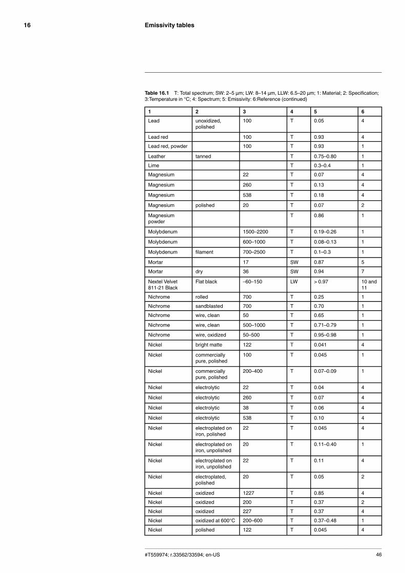
Emissivity tables16
Table 16.1 T: Total spectrum; SW: 2–5 µm; LW: 8–14 µm, LLW: 6.5–20 µm; 1: Material; 2: Specification;3:Temperature in °C; 4: Spectrum; 5: Emissivity: 6:Reference (continued)
1 2 3 4 5 6
Lead unoxidized,polished
100 T 0.05 4
Lead red 100 T 0.93 4
Lead red, powder 100 T 0.93 1
Leather tanned T 0.75–0.80 1
Lime T 0.3–0.4 1
Magnesium 22 T 0.07 4
Magnesium 260 T 0.13 4
Magnesium 538 T 0.18 4
Magnesium polished 20 T 0.07 2
Magnesiumpowder
T 0.86 1
Molybdenum 1500–2200 T 0.19–0.26 1
Molybdenum 600–1000 T 0.08–0.13 1
Molybdenum filament 700–2500 T 0.1–0.3 1
Mortar 17 SW 0.87 5
Mortar dry 36 SW 0.94 7
Nextel Velvet811-21 Black
Flat black –60–150 LW > 0.97 10 and11
Nichrome rolled 700 T 0.25 1
Nichrome sandblasted 700 T 0.70 1
Nichrome wire, clean 50 T 0.65 1
Nichrome wire, clean 500–1000 T 0.71–0.79 1
Nichrome wire, oxidized 50–500 T 0.95–0.98 1
Nickel bright matte 122 T 0.041 4
Nickel commerciallypure, polished
100 T 0.045 1
Nickel commerciallypure, polished
200–400 T 0.07–0.09 1
Nickel electrolytic 22 T 0.04 4
Nickel electrolytic 260 T 0.07 4
Nickel electrolytic 38 T 0.06 4
Nickel electrolytic 538 T 0.10 4
Nickel electroplated oniron, polished
22 T 0.045 4
Nickel electroplated oniron, unpolished
20 T 0.11–0.40 1
Nickel electroplated oniron, unpolished
22 T 0.11 4
Nickel electroplated,polished
20 T 0.05 2
Nickel oxidized 1227 T 0.85 4
Nickel oxidized 200 T 0.37 2
Nickel oxidized 227 T 0.37 4
Nickel oxidized at 600°C 200–600 T 0.37–0.48 1
Nickel polished 122 T 0.045 4
#T559974; r.33562/33594; en-US 46
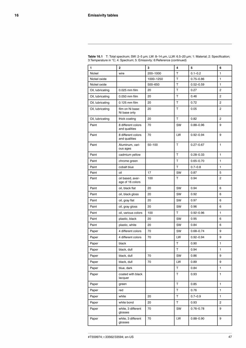
Emissivity tables16
Table 16.1 T: Total spectrum; SW: 2–5 µm; LW: 8–14 µm, LLW: 6.5–20 µm; 1: Material; 2: Specification;3:Temperature in °C; 4: Spectrum; 5: Emissivity: 6:Reference (continued)
1 2 3 4 5 6
Nickel wire 200–1000 T 0.1–0.2 1
Nickel oxide 1000–1250 T 0.75–0.86 1
Nickel oxide 500–650 T 0.52–0.59 1
Oil, lubricating 0.025 mm film 20 T 0.27 2
Oil, lubricating 0.050 mm film 20 T 0.46 2
Oil, lubricating 0.125 mm film 20 T 0.72 2
Oil, lubricating film on Ni base:Ni base only
20 T 0.05 2
Oil, lubricating thick coating 20 T 0.82 2
Paint 8 different colorsand qualities
70 SW 0.88–0.96 9
Paint 8 different colorsand qualities
70 LW 0.92–0.94 9
Paint Aluminum, vari-ous ages
50–100 T 0.27–0.67 1
Paint cadmium yellow T 0.28–0.33 1
Paint chrome green T 0.65–0.70 1
Paint cobalt blue T 0.7–0.8 1
Paint oil 17 SW 0.87 5
Paint oil based, aver-age of 16 colors
100 T 0.94 2
Paint oil, black flat 20 SW 0.94 6
Paint oil, black gloss 20 SW 0.92 6
Paint oil, gray flat 20 SW 0.97 6
Paint oil, gray gloss 20 SW 0.96 6
Paint oil, various colors 100 T 0.92–0.96 1
Paint plastic, black 20 SW 0.95 6
Paint plastic, white 20 SW 0.84 6
Paper 4 different colors 70 SW 0.68–0.74 9
Paper 4 different colors 70 LW 0.92–0.94 9
Paper black T 0.90 1
Paper black, dull T 0.94 1
Paper black, dull 70 SW 0.86 9
Paper black, dull 70 LW 0.89 9
Paper blue, dark T 0.84 1
Paper coated with blacklacquer
T 0.93 1
Paper green T 0.85 1
Paper red T 0.76 1
Paper white 20 T 0.7–0.9 1
Paper white bond 20 T 0.93 2
Paper white, 3 differentglosses
70 SW 0.76–0.78 9
Paper white, 3 differentglosses
70 LW 0.88–0.90 9
#T559974; r.33562/33594; en-US 47
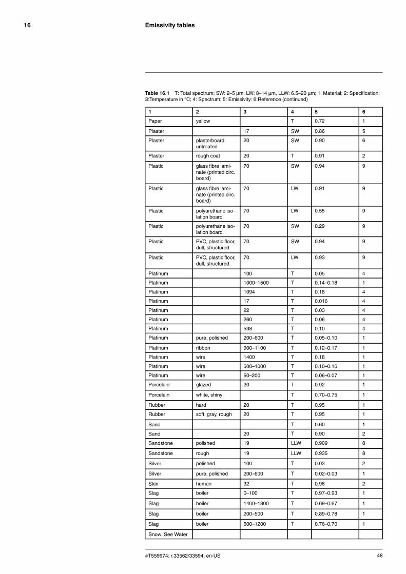
Emissivity tables16
Table 16.1 T: Total spectrum; SW: 2–5 µm; LW: 8–14 µm, LLW: 6.5–20 µm; 1: Material; 2: Specification;3:Temperature in °C; 4: Spectrum; 5: Emissivity: 6:Reference (continued)
1 2 3 4 5 6
Paper yellow T 0.72 1
Plaster 17 SW 0.86 5
Plaster plasterboard,untreated
20 SW 0.90 6
Plaster rough coat 20 T 0.91 2
Plastic glass fibre lami-nate (printed circ.board)
70 SW 0.94 9
Plastic glass fibre lami-nate (printed circ.board)
70 LW 0.91 9
Plastic polyurethane iso-lation board
70 LW 0.55 9
Plastic polyurethane iso-lation board
70 SW 0.29 9
Plastic PVC, plastic floor,dull, structured
70 SW 0.94 9
Plastic PVC, plastic floor,dull, structured
70 LW 0.93 9
Platinum 100 T 0.05 4
Platinum 1000–1500 T 0.14–0.18 1
Platinum 1094 T 0.18 4
Platinum 17 T 0.016 4
Platinum 22 T 0.03 4
Platinum 260 T 0.06 4
Platinum 538 T 0.10 4
Platinum pure, polished 200–600 T 0.05–0.10 1
Platinum ribbon 900–1100 T 0.12–0.17 1
Platinum wire 1400 T 0.18 1
Platinum wire 500–1000 T 0.10–0.16 1
Platinum wire 50–200 T 0.06–0.07 1
Porcelain glazed 20 T 0.92 1
Porcelain white, shiny T 0.70–0.75 1
Rubber hard 20 T 0.95 1
Rubber soft, gray, rough 20 T 0.95 1
Sand T 0.60 1
Sand 20 T 0.90 2
Sandstone polished 19 LLW 0.909 8
Sandstone rough 19 LLW 0.935 8
Silver polished 100 T 0.03 2
Silver pure, polished 200–600 T 0.02–0.03 1
Skin human 32 T 0.98 2
Slag boiler 0–100 T 0.97–0.93 1
Slag boiler 1400–1800 T 0.69–0.67 1
Slag boiler 200–500 T 0.89–0.78 1
Slag boiler 600–1200 T 0.76–0.70 1
Snow: See Water
#T559974; r.33562/33594; en-US 48
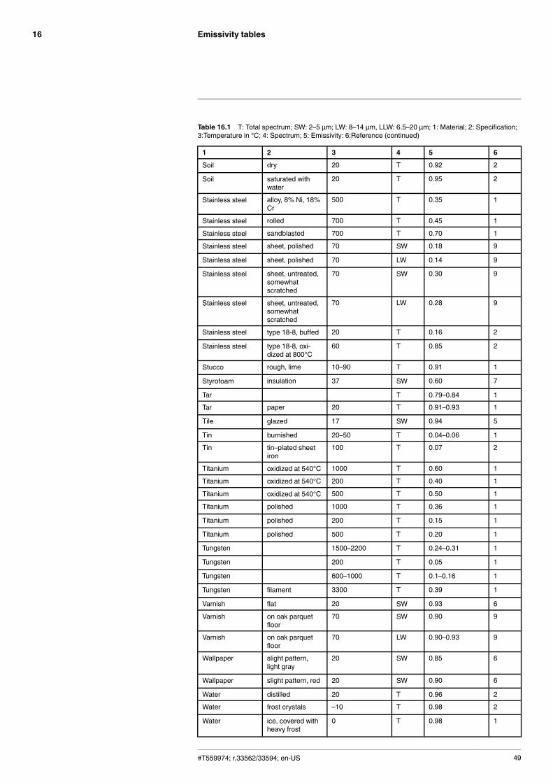
Emissivity tables16
Table 16.1 T: Total spectrum; SW: 2–5 µm; LW: 8–14 µm, LLW: 6.5–20 µm; 1: Material; 2: Specification;3:Temperature in °C; 4: Spectrum; 5: Emissivity: 6:Reference (continued)
1 2 3 4 5 6
Soil dry 20 T 0.92 2
Soil saturated withwater
20 T 0.95 2
Stainless steel alloy, 8% Ni, 18%Cr
500 T 0.35 1
Stainless steel rolled 700 T 0.45 1
Stainless steel sandblasted 700 T 0.70 1
Stainless steel sheet, polished 70 SW 0.18 9
Stainless steel sheet, polished 70 LW 0.14 9
Stainless steel sheet, untreated,somewhatscratched
70 SW 0.30 9
Stainless steel sheet, untreated,somewhatscratched
70 LW 0.28 9
Stainless steel type 18-8, buffed 20 T 0.16 2
Stainless steel type 18-8, oxi-dized at 800°C
60 T 0.85 2
Stucco rough, lime 10–90 T 0.91 1
Styrofoam insulation 37 SW 0.60 7
Tar T 0.79–0.84 1
Tar paper 20 T 0.91–0.93 1
Tile glazed 17 SW 0.94 5
Tin burnished 20–50 T 0.04–0.06 1
Tin tin–plated sheetiron
100 T 0.07 2
Titanium oxidized at 540°C 1000 T 0.60 1
Titanium oxidized at 540°C 200 T 0.40 1
Titanium oxidized at 540°C 500 T 0.50 1
Titanium polished 1000 T 0.36 1
Titanium polished 200 T 0.15 1
Titanium polished 500 T 0.20 1
Tungsten 1500–2200 T 0.24–0.31 1
Tungsten 200 T 0.05 1
Tungsten 600–1000 T 0.1–0.16 1
Tungsten filament 3300 T 0.39 1
Varnish flat 20 SW 0.93 6
Varnish on oak parquetfloor
70 SW 0.90 9
Varnish on oak parquetfloor
70 LW 0.90–0.93 9
Wallpaper slight pattern,light gray
20 SW 0.85 6
Wallpaper slight pattern, red 20 SW 0.90 6
Water distilled 20 T 0.96 2
Water frost crystals –10 T 0.98 2
Water ice, covered withheavy frost
0 T 0.98 1
#T559974; r.33562/33594; en-US 49
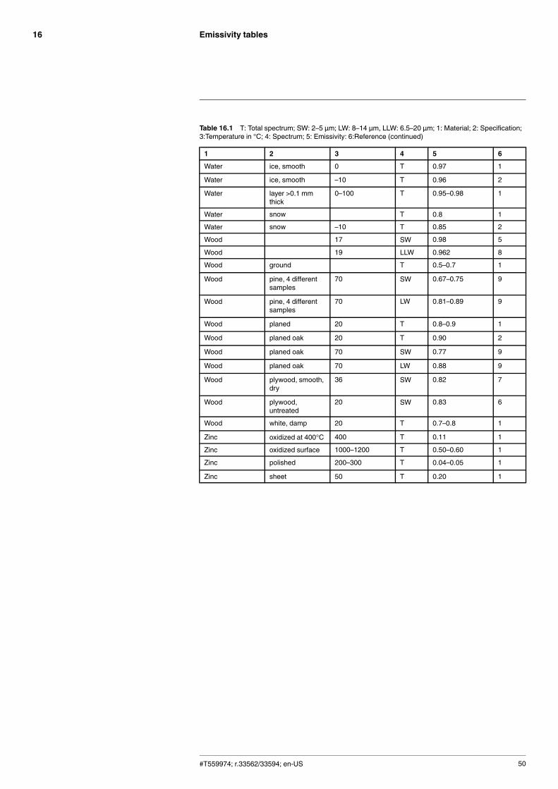
Emissivity tables16
Table 16.1 T: Total spectrum; SW: 2–5 µm; LW: 8–14 µm, LLW: 6.5–20 µm; 1: Material; 2: Specification;3:Temperature in °C; 4: Spectrum; 5: Emissivity: 6:Reference (continued)
1 2 3 4 5 6
Water ice, smooth 0 T 0.97 1
Water ice, smooth –10 T 0.96 2
Water layer >0.1 mmthick
0–100 T 0.95–0.98 1
Water snow T 0.8 1
Water snow –10 T 0.85 2
Wood 17 SW 0.98 5
Wood 19 LLW 0.962 8
Wood ground T 0.5–0.7 1
Wood pine, 4 differentsamples
70 SW 0.67–0.75 9
Wood pine, 4 differentsamples
70 LW 0.81–0.89 9
Wood planed 20 T 0.8–0.9 1
Wood planed oak 20 T 0.90 2
Wood planed oak 70 SW 0.77 9
Wood planed oak 70 LW 0.88 9
Wood plywood, smooth,dry
36 SW 0.82 7
Wood plywood,untreated
20 SW 0.83 6
Wood white, damp 20 T 0.7–0.8 1
Zinc oxidized at 400°C 400 T 0.11 1
Zinc oxidized surface 1000–1200 T 0.50–0.60 1
Zinc polished 200–300 T 0.04–0.05 1
Zinc sheet 50 T 0.20 1
#T559974; r.33562/33594; en-US 50

A note on the technical production of this publicationThis publication was produced using XML — the eXtensible Markup Language. For more informationabout XML, please visit http://www.w3.org/XML/A note on the typeface used in this publicationThis publication was typeset using Linotype Helvetica™World. Helvetica™ was designed by MaxMiedinger (1910–1980)LOEF (List Of Effective Files)T501136.xml; en-US; 33562; 2016-02-18T505552.xml; en-US; 9599; 2013-11-05T505876.xml; en-US; 26608; 2015-06-10T505469.xml; en-US; 23215; 2015-02-19T505013.xml; en-US; 32063; 2016-01-08T505859.xml; en-US; 33562; 2016-02-18T505860.xml; en-US; 33562; 2016-02-18T505862.xml; en-US; 33562; 2016-02-18T505863.xml; en-US; 33562; 2016-02-18T505875.xml; en-US; 33489; 2016-02-18T505470.xml; en-US; 12154; 2014-03-06T505012.xml; en-US; 32556; 2016-01-20T505007.xml; en-US; 33543; 2016-02-18T505004.xml; en-US; 12154; 2014-03-06T505005.xml; en-US; 33543; 2016-02-18T505002.xml; en-US; 33518; 2016-02-18
#T559974; r.33562/33594; en-US 52


last page
Publ. No.: T559974Commit: 33562Head: 33594Language: en-USModified: 2016-02-18Formatted: 2016-02-18
Websitehttp://www.flir.comCustomer supporthttp://support.flir.comCopyright© 2016, FLIR Systems, Inc. All rights reserved worldwide.DisclaimerSpecifications subject to change without further notice. Models and accessories subject to regional market considerations. License procedures may apply.Products described herein may be subject to US Export Regulations. Please refer to [email protected] with any questions.


