Table of Contents Table of Contents............................................................................................................................... 2 General guidelines ............................................................................................................................. 4
What describes this manual? ......................................................................................................... 4 !! Warnings !!.................................................................................................................................. 4 Text ............................................................................................................................................... 4
General description ............................................................................................................................ 5 Description of the Fire Pump Controller .......................................................................................... 5 What is in the package?................................................................................................................. 6 IL-NT RS232 communication module ............................................................................................. 7 IL-NT-232-485 communication module........................................................................................... 7 IL-NT S USB communication module ............................................................................................. 8 IL-NT AOU8 – 8 gauge driver module............................................................................................. 8 IL-NT IO1 – extension I/O module .................................................................................................. 9 IL-NT-AIO .................................................................................................................................... 10 IL-NT BIO8 Binary input/output module ........................................................................................ 11 IB-Lite Ethernet communication plug-in card................................................................................. 12 IL-NT RD Remote display ............................................................................................................ 13 Remote announciator IGL-RA15 .................................................................................................. 13
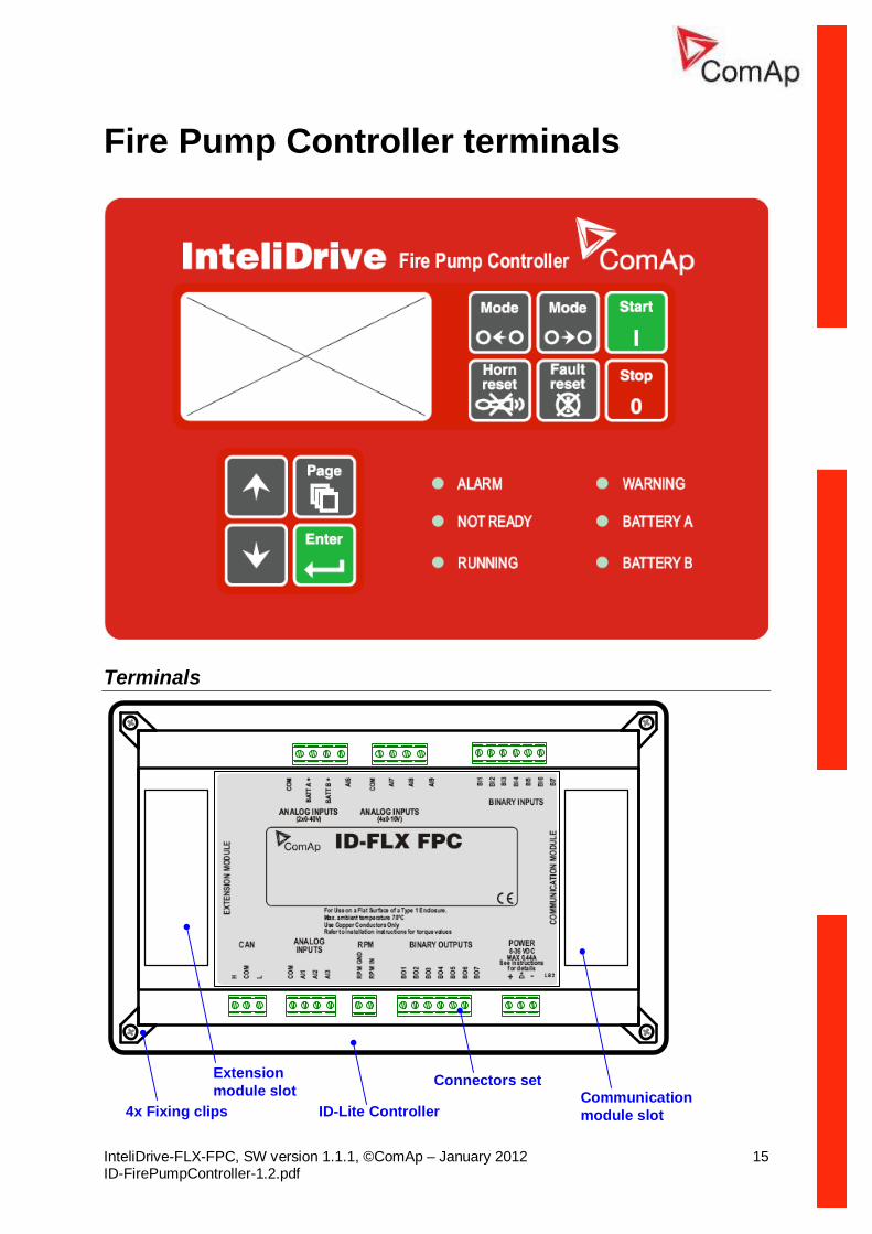
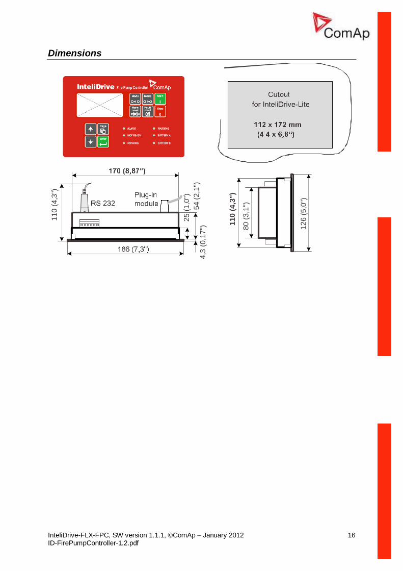
Fire Pump Controller terminals ......................................................................................................... 15 Terminals..................................................................................................................................... 15 Dimensions.................................................................................................................................. 16
Recommended wiring....................................................................................................................... 17 Fire Pump Controller – Wiring diagram........................................................................................ 17
Getting started ................................................................................................................................. 18 How to install ............................................................................................................................... 18 Analog inputs............................................................................................................................... 20 Extension modules - CAN bus connection.................................................................................... 22 Analog outputs............................................................................................................................. 22
Inputs and outputs............................................................................................................................ 25 Binary inputs FIRE PUMP CONTROLLER - default...................................................................... 25 Binary inputs – list........................................................................................................................ 25 Binary outputs FIRE PUMP CONTROLLER - default................................................................... 28 Binary outputs - list....................................................................................................................... 28 Analog inputs............................................................................................................................... 34
ECU-controlled engine support......................................................................................................... 49 Values read from ECU ................................................................................................................. 51 Diagnostic messages read from ECU........................................................................................... 51 List of received diagnostic codes.................................................................................................. 51 Analog inputs............................................................................................................................... 52
Sensor specification ......................................................................................................................... 54 Background of the sensor calibration............................................................................................ 54 Default sensor settings................................................................................................................. 54
How to select the engine mode ? ................................................................................................. 56 How to view measured data? ....................................................................................................... 56 How to view and edit set points? .................................................................................................. 56 How to find active alarms ? .......................................................................................................... 57 How to list History records ?......................................................................................................... 57 MEASUREMENT screens description .......................................................................................... 57 Chart guide to menus and pushbutton’s operation ........................................................................ 60
Function description ......................................................................................................................... 61 OFF mode ................................................................................................................................... 61 TEST mode.................................................................................................................................. 61 AUT mode ................................................................................................................................... 61
Engine operation states.................................................................................................................... 63 List of possible alarms.................................................................................................................. 63 History file.................................................................................................................................... 64
Remote control and data logging...................................................................................................... 66 Direct connection to the PC.......................................................................................................... 66 PC software - LiteEdit (3.0 or higher)............................................................................................ 66 Modbus protocol .......................................................................................................................... 66
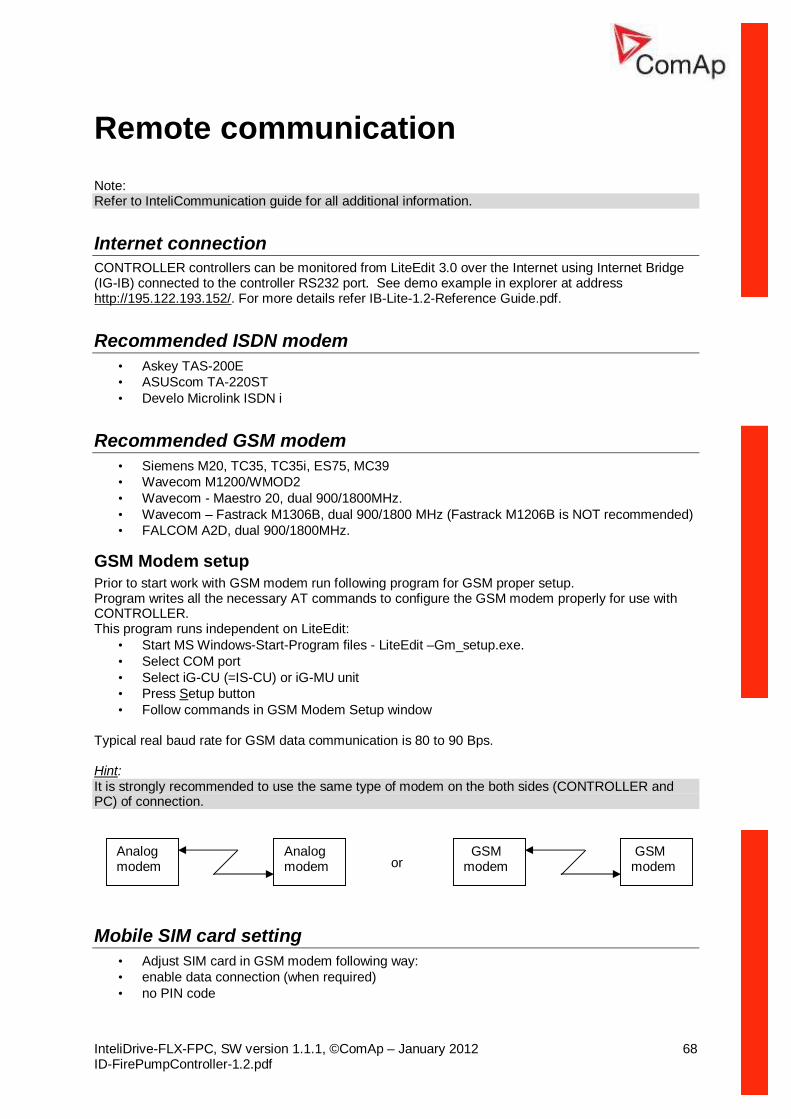
Remote communication.................................................................................................................... 68 Internet connection....................................................................................................................... 68 Recommended ISDN modem....................................................................................................... 68 Recommended GSM modem ....................................................................................................... 68 Mobile SIM card setting................................................................................................................ 68
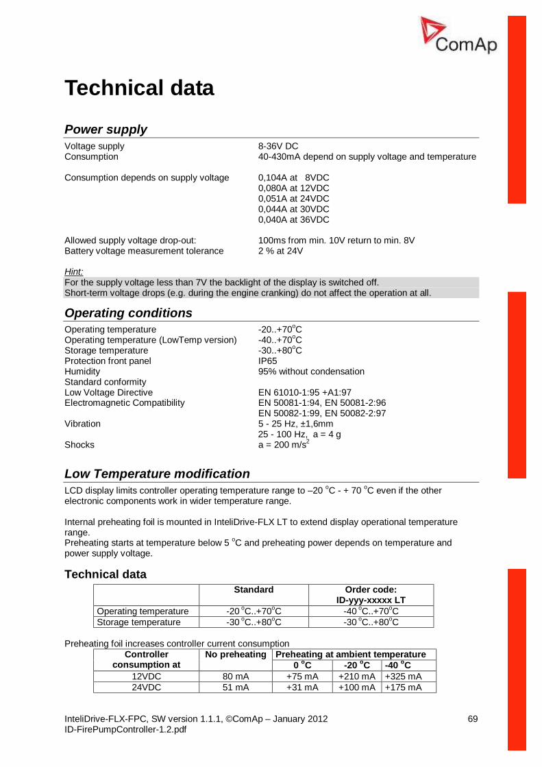
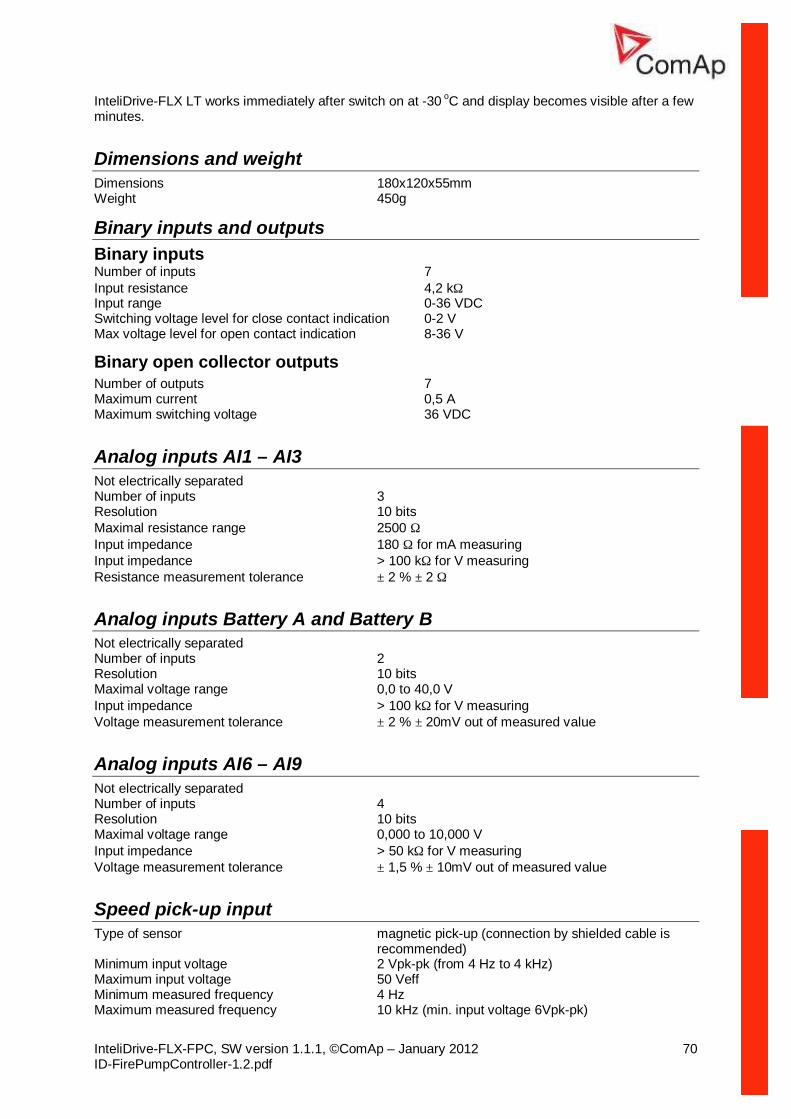
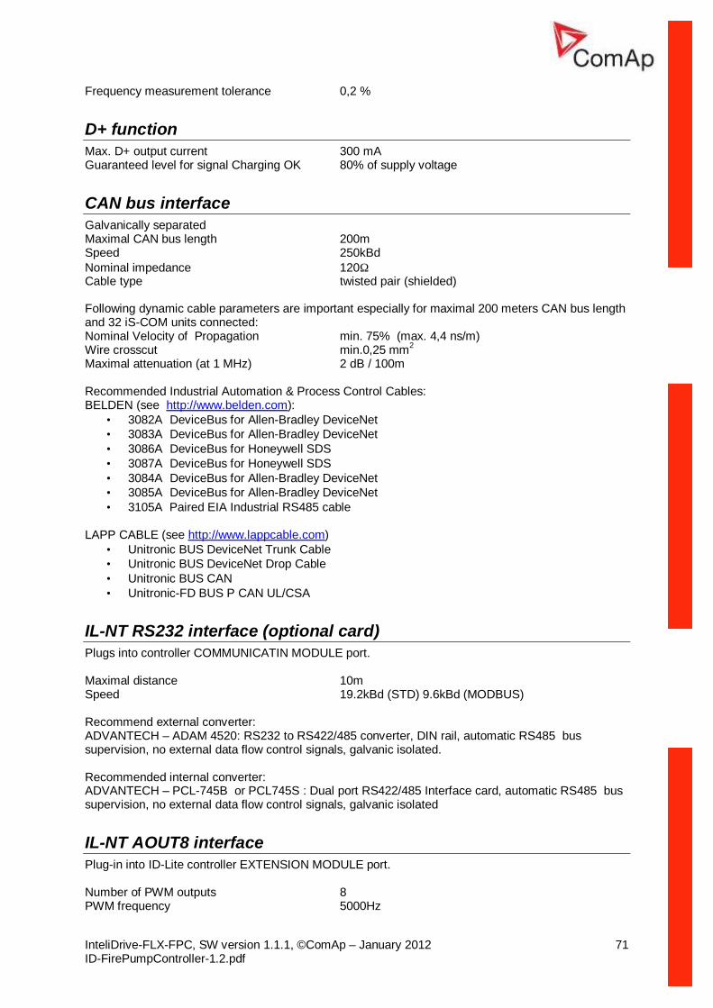
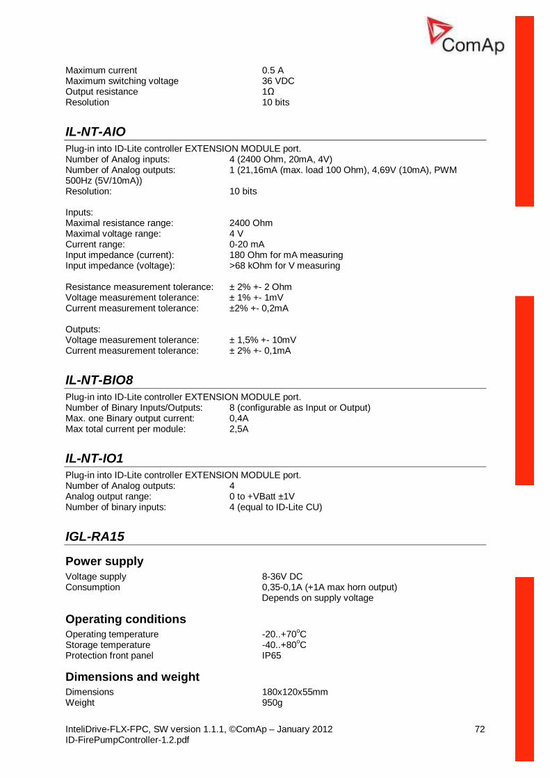
Technical data.................................................................................................................................. 69 Power supply ............................................................................................................................... 69 Operating conditions .................................................................................................................... 69 Low Temperature modification ..................................................................................................... 69 Dimensions and weight ................................................................................................................ 70 Binary inputs and outputs............................................................................................................. 70 Analog inputs AI1 – AI3................................................................................................................ 70 Analog inputs Battery A and Battery B.......................................................................................... 70 Analog inputs AI6 – AI9................................................................................................................ 70 Speed pick-up input ..................................................................................................................... 70 D+ function .................................................................................................................................. 71 CAN bus interface........................................................................................................................ 71 IL-NT RS232 interface (optional card) .......................................................................................... 71 IL-NT AOUT8 interface................................................................................................................. 71 IL-NT-AIO .................................................................................................................................... 72 IL-NT-BIO8 .................................................................................................................................. 72 IL-NT-IO1..................................................................................................................................... 72 IGL-RA15..................................................................................................................................... 72
What describes this manual? This Reference guide describes FIRE PUMP CONTROLLER functionality designed for single engine driven fire pumps and provides general information how to install and operate. Controller functionality is based on standard InteliDrive - Diesel Control Unit with modification to follow NFPA 20 standard. This manual is dedicated for Fire Pump control panel builders, Operators and for everybody who is concerned with installation, operation and maintenance of the engine applications.
!! Warnings !!
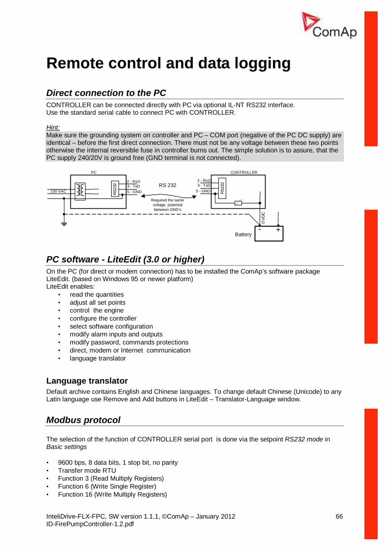
Remote control Fire Pump Controller can be remotely controlled. In case of the work on the engine check, that nobody can remotely start the engine. To be sure:
Disconnect remote control via RS232 line Disconnect input REM START/STOP
or Disconnect output STARTER
Because of large variety of controller parameters settings, it is not possible to describe any combination. Some of controller functions are subject of changes depend on SW version. The data in this manual only describes the product and are not warranty of performance or characteristic.
Text PAGE (Capital letters in the frame) buttons on the front panel Break Return (Italic) set points Engine protections (Bold) Set point group REMOTE START/STOP (Capital letters) binary inputs and outputs Note: ComAp believes that all information provided herein is correct and reliable and reserves the right to update at any time. ComAp does not assume any responsibility for its use unless otherwise expressly undertaken. Note: SW and HW must be compatible otherwise the function will be disabled. If wrong software is downloaded, message HARDWARE INCOMPATIBLE appears on controller screen. In this case use Boot load (jumper) programming – close Boot jumper and follow instructions in LiteEdit, download correct software.
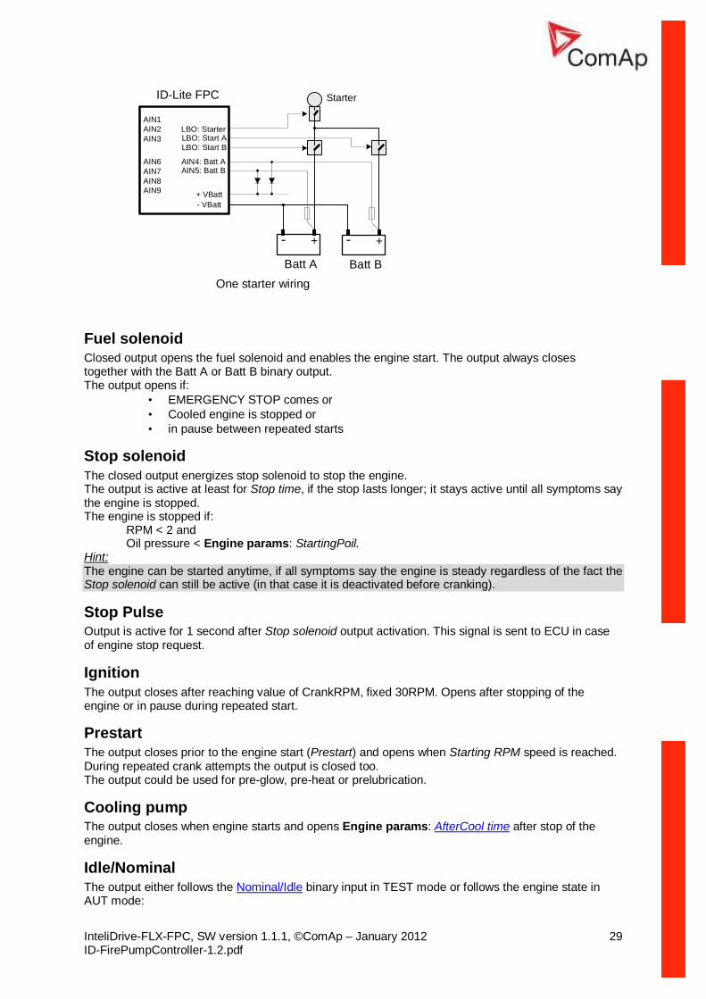
Description of the Fire Pump Controller Fire Pump Controller is a comprehensive controller for single engine pump sets. Controller is equipped with a powerful graphic display showing icons, symbols and bar-graphs for intuitive operation, which sets, together with high functionality, new standards in engine-set controls. The Fire Pump Controller functionality corresponds to NFPA 20 standard. Controller automatically starts, stops the engine on external signal (see Remote Start/Stop) in AUT mode or by pressing panel push buttons if there are no active or not confirmed Sd alarms active in TEST mode. Controller ignores engine protections except Emergency Stop and Overspeed protection in AUT mode. The engine can be energized by two batteries A and B and two separate Starters - see the principal wiring diagram. The controller monitors voltages of two batteries A and B on AIN4 and AIN5 Analog inputs.
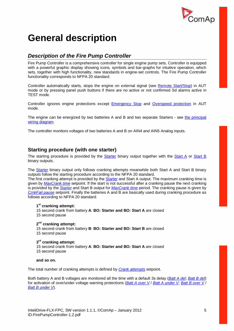
Starting procedure (with one starter) The starting procedure is provided by the Starter binary output together with the Start A or Start B binary outputs. The Starter binary output only follows cranking attempts meanwhile both Start A and Start B binary outputs follow the starting procedure according to the NFPA 20 standard. The first cranking attempt is provided by the Starter and Start A output. The maximum cranking time is given by MaxCrank time setpoint. If the start is not successful after a cranking pause the next cranking is provided by the Starter and Start B output for MaxCrank time period. The cranking pause is given by CrnkFail pause setpoint. Finally the batteries A and B are basically used during cranking procedure as follows according to NFPA 20 standard:
1st cranking attempt: 15 second crank from battery A: BO: Starter and BO: Start A are closed 15 second pause 2nd cranking attempt: 15 second crank from battery B: BO: Starter and BO: Start B are closed 15 second pause 3rd cranking attempt: 15 second crank from battery A: BO: Starter and BO: Start A are closed 15 second pause and so on.
The total number of cranking attempts is defined by Crank attempts setpoint. Both battery A and B voltages are monitored all the time with a default 3s delay (Batt A del; Batt B del) for activation of over/under voltage warning protections (Batt A over V / Batt A under V; Batt B over V / Batt B under V).
In the case when the voltage of one of the batteries gets out of limits of the operation level the battery becomes locked out from further cranking and following alarms are displayed:
• for fail of a Battery A: Wrn BatteryA; • for fail of a Battery B: Wrn BatteryB; • in the case the power supply voltage of the controller had dropped under 8 VDC during
previous cranking it caused a restart of the controller and there is an alarm Wrn Batt flat displayed after restart of the controller (also see the Power supply chapter).
In the case when both battery voltages A and B get out of limits, the crank procedure will follow both batteries A and B again alternating binary outputs Batt A and Batt B.
In the case of un unsuccessful starting attempt, LBO Starter is activated 400 ms after the activation of the LBO Start x (x=A or B) and is deactivated 400 ms before the deactivation of the LBO Start x.
When the starting attempt is successful so that the engine becomes running, the LBO Start x remains activated until the end of stopping procedure (the Stop Solenoid must be energized during the Stop time). The same LBO Start x (the same battery) will also be used as the first one for the next cranking procedure. Hint: After the controller initialization, the first starting attempt is always from the battery A.
What is in the package? Accessories Description Optional / Obligatory ID-FLX FPC InteliDrive-Lite central unit Obligatory Communication plug-in IL-NT RS232 RS232 communication card Optional plug-in IL-NT 232/485 Combined communication card IL-NT S USB USB communication card Optional plug-in IB-Lite Ethernet/Internet interface Optional plug-in Extension plug-in IL-NT AOUT8 8 AOUT Gauge driver card Optional plug-in IL-NT AIO 4xAIN + 1x AOUT Optional plug-in IL-NT IO1 4xBIN + 4xAOUT Optional plug-in IL-NT BIO8 8x BIN or BOUT Optional plug-in External modules IL-NT RD Remote display Optional IGL-RA15 Remote annunciator Optional IG-IB Internet communication bridge Optional
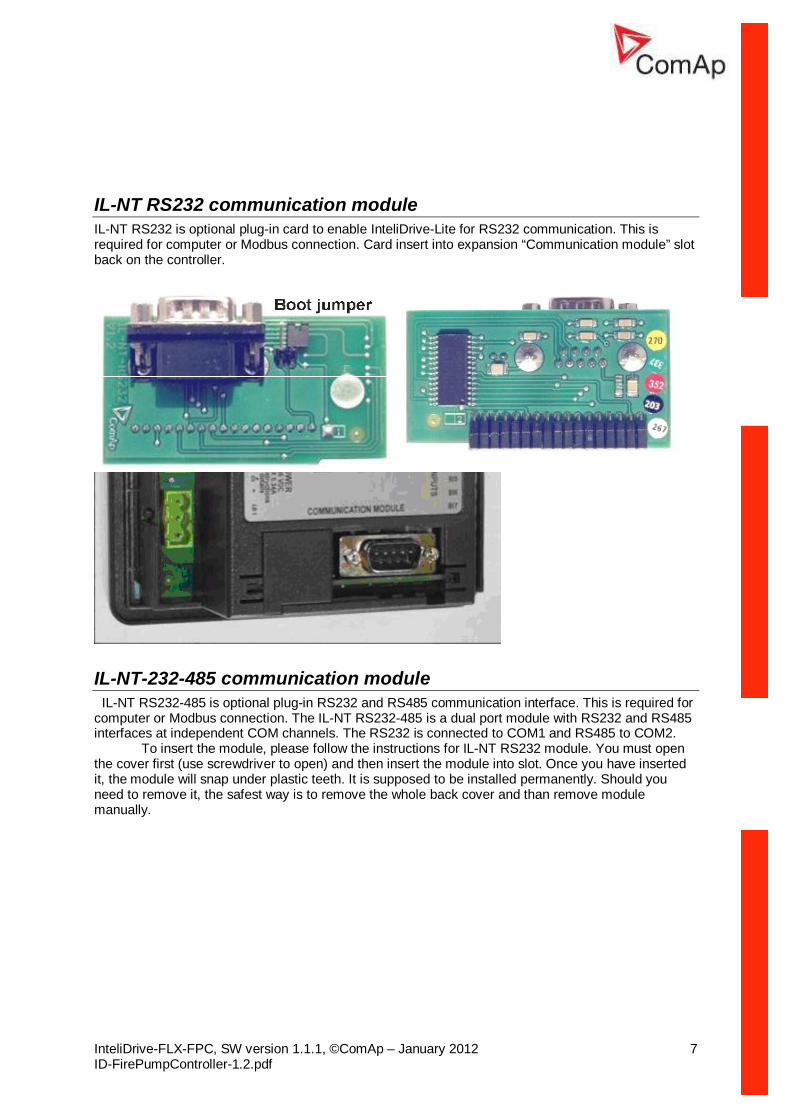
IL-NT RS232 communication module IL-NT RS232 is optional plug-in card to enable InteliDrive-Lite for RS232 communication. This is required for computer or Modbus connection. Card insert into expansion “Communication module” slot back on the controller.
IL-NT-232-485 communication module IL-NT RS232-485 is optional plug-in RS232 and RS485 communication interface. This is required for computer or Modbus connection. The IL-NT RS232-485 is a dual port module with RS232 and RS485 interfaces at independent COM channels. The RS232 is connected to COM1 and RS485 to COM2.
To insert the module, please follow the instructions for IL-NT RS232 module. You must open the cover first (use screwdriver to open) and then insert the module into slot. Once you have inserted it, the module will snap under plastic teeth. It is supposed to be installed permanently. Should you need to remove it, the safest way is to remove the whole back cover and than remove module manually.
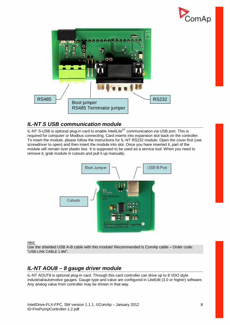
IL-NT S USB communication module IL-NT S-USB is optional plug-in card to enable InteliLiteNT communication via USB port. This is required for computer or Modbus connecting. Card inserts into expansion slot back on the controller. To insert the module, please follow the instructions for IL-NT RS232 module. Open the cover first (use screwdriver to open) and then insert the module into slot. Once you have inserted it, part of the module will remain over plastic box. It is supposed to be used as a service tool. When you need to remove it, grab module in cutouts and pull it up manually.
Hint: Use the shielded USB A-B cable with this module! Recommended is ComAp cable – Order code: “USB-LINK CABLE 1.8M”.
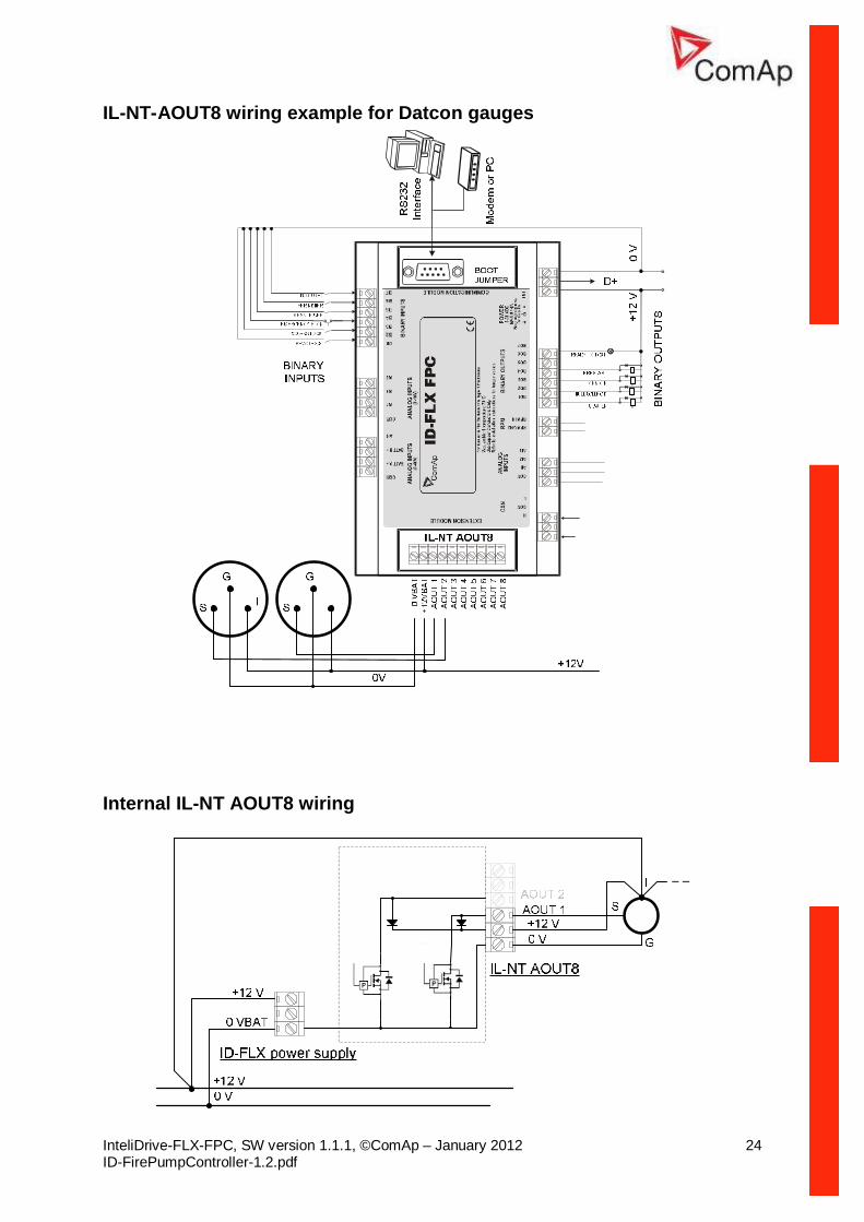
IL-NT AOU8 – 8 gauge driver module IL-NT AOUT8 is optional plug-in card. Through this card controller can drive up to 8 VDO style industrial/automotive gauges. Gauge type and value are configured in LiteEdit (3.0 or higher) software. Any analog value from controller may be shown in that way.
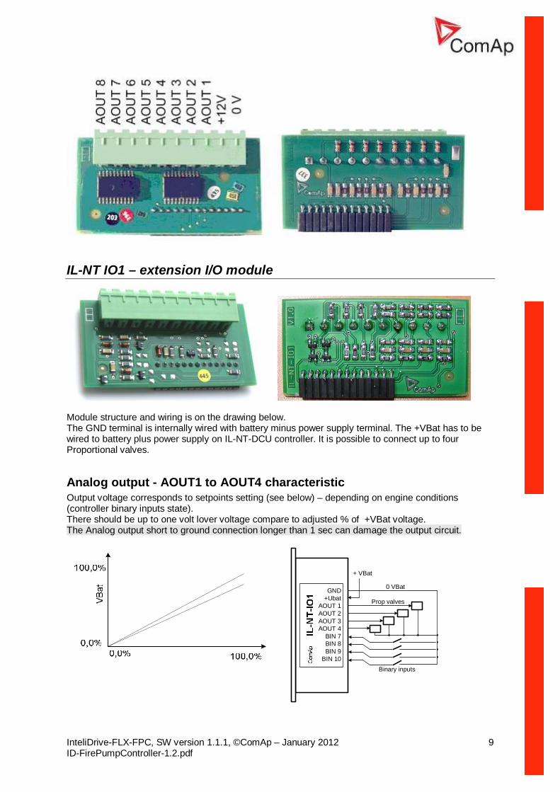
Module structure and wiring is on the drawing below. The GND terminal is internally wired with battery minus power supply terminal. The +VBat has to be wired to battery plus power supply on IL-NT-DCU controller. It is possible to connect up to four Proportional valves.
Analog output - AOUT1 to AOUT4 characteristic Output voltage corresponds to setpoints setting (see below) – depending on engine conditions (controller binary inputs state). There should be up to one volt lover voltage compare to adjusted % of +VBat voltage. The Analog output short to ground connection longer than 1 sec can damage the output circuit.
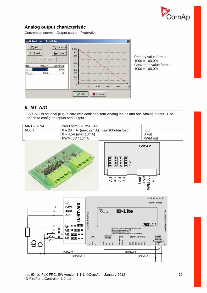
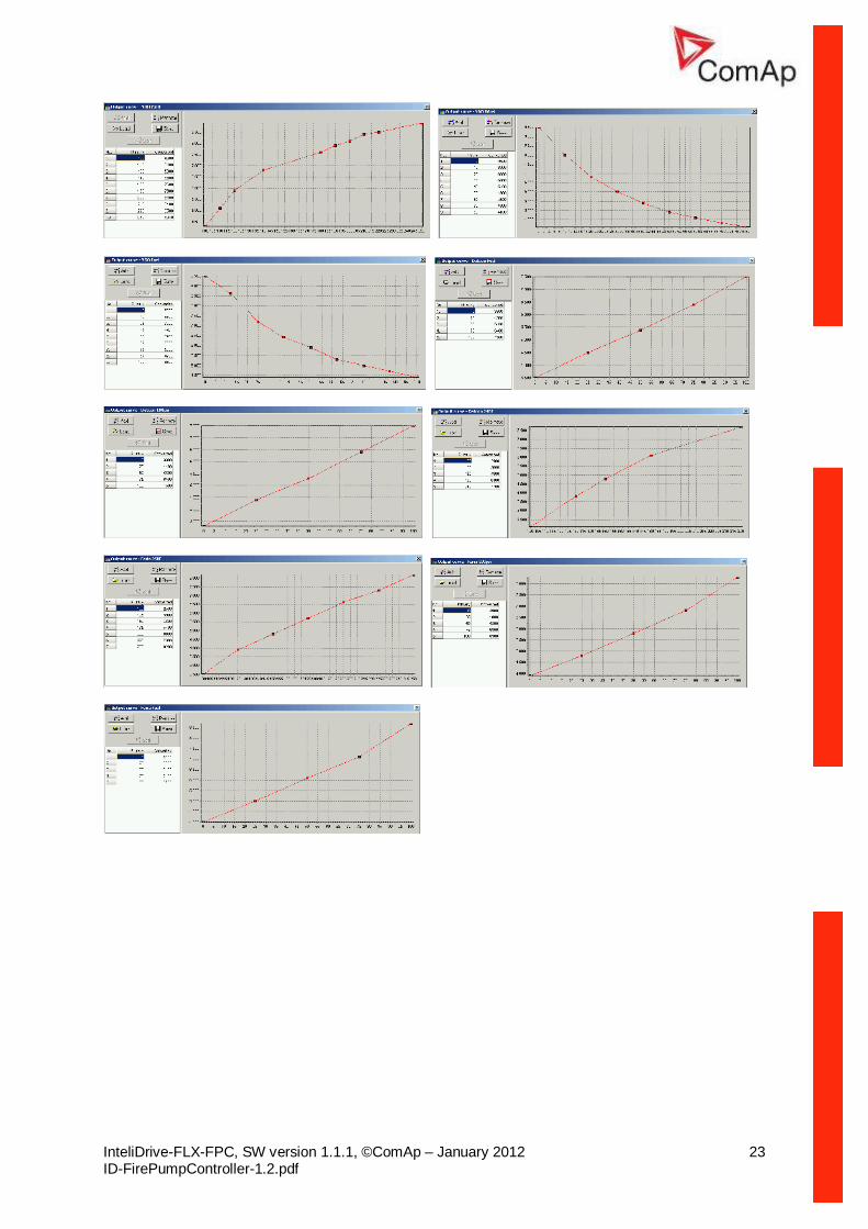
Analog output characteristic Conversion curves - Output curve – PropValve
Primary value format: 1000 = 100,0% Converted value format: 1000 = 100,0%
IL-NT-AIO IL-NT AIO is optional plug-in card with additional four Analog inputs and one Analog output. Use LiteEdit to configure Inputs and Output.. AIN1 – AIN4 2600 ohm / 20 mA / 4V AOUT 0 – 20 mA (max 22mA) max 100ohm load
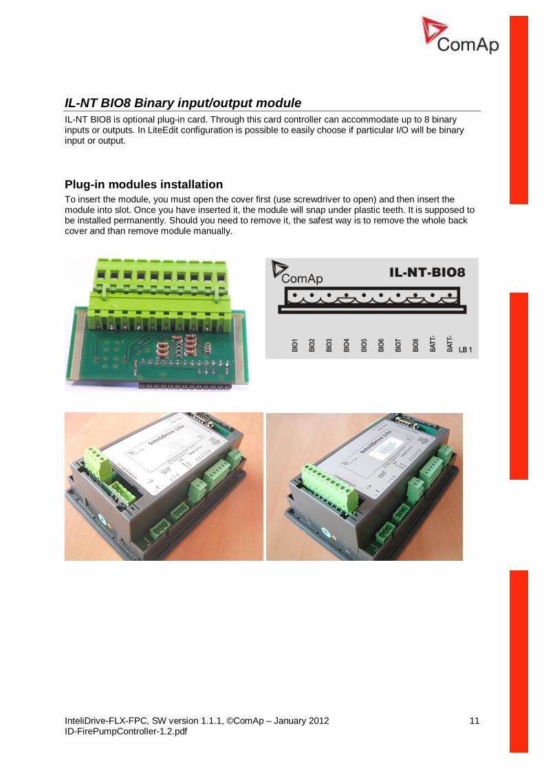
IL-NT BIO8 Binary input/output module IL-NT BIO8 is optional plug-in card. Through this card controller can accommodate up to 8 binary inputs or outputs. In LiteEdit configuration is possible to easily choose if particular I/O will be binary input or output.
Plug-in modules installation To insert the module, you must open the cover first (use screwdriver to open) and then insert the module into slot. Once you have inserted it, the module will snap under plastic teeth. It is supposed to be installed permanently. Should you need to remove it, the safest way is to remove the whole back cover and than remove module manually.
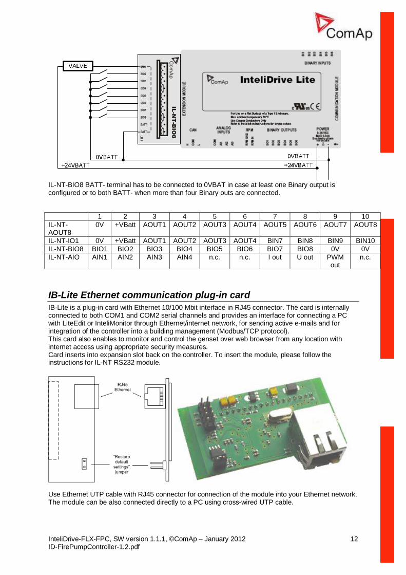
IL-NT-BIO8 BATT- terminal has to be connected to 0VBAT in case at least one Binary output is configured or to both BATT- when more than four Binary outs are connected.
IL-NT-IO1 0V +VBatt AOUT1 AOUT2 AOUT3 AOUT4 BIN7 BIN8 BIN9 BIN10 IL-NT-BIO8 BIO1 BIO2 BIO3 BIO4 BIO5 BIO6 BIO7 BIO8 0V 0V IL-NT-AIO AIN1 AIN2 AIN3 AIN4 n.c. n.c. I out U out PWM
out n.c.
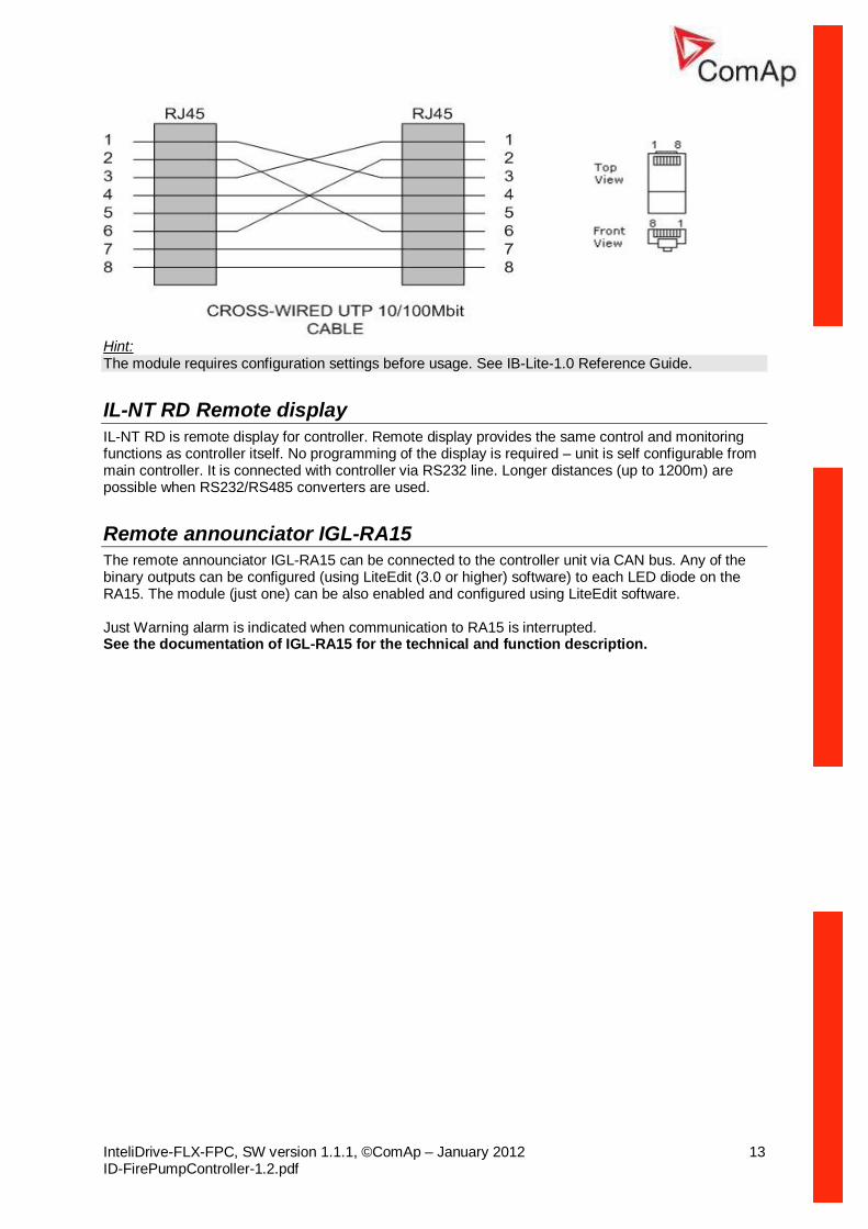
IB-Lite Ethernet communication plug-in card IB-Lite is a plug-in card with Ethernet 10/100 Mbit interface in RJ45 connector. The card is internally connected to both COM1 and COM2 serial channels and provides an interface for connecting a PC with LiteEdit or InteliMonitor through Ethernet/internet network, for sending active e-mails and for integration of the controller into a building management (Modbus/TCP protocol). This card also enables to monitor and control the genset over web browser from any location with internet access using appropriate security measures. Card inserts into expansion slot back on the controller. To insert the module, please follow the instructions for IL-NT RS232 module.
Use Ethernet UTP cable with RJ45 connector for connection of the module into your Ethernet network. The module can be also connected directly to a PC using cross-wired UTP cable.
Hint: The module requires configuration settings before usage. See IB-Lite-1.0 Reference Guide.
IL-NT RD Remote display IL-NT RD is remote display for controller. Remote display provides the same control and monitoring functions as controller itself. No programming of the display is required – unit is self configurable from main controller. It is connected with controller via RS232 line. Longer distances (up to 1200m) are possible when RS232/RS485 converters are used.
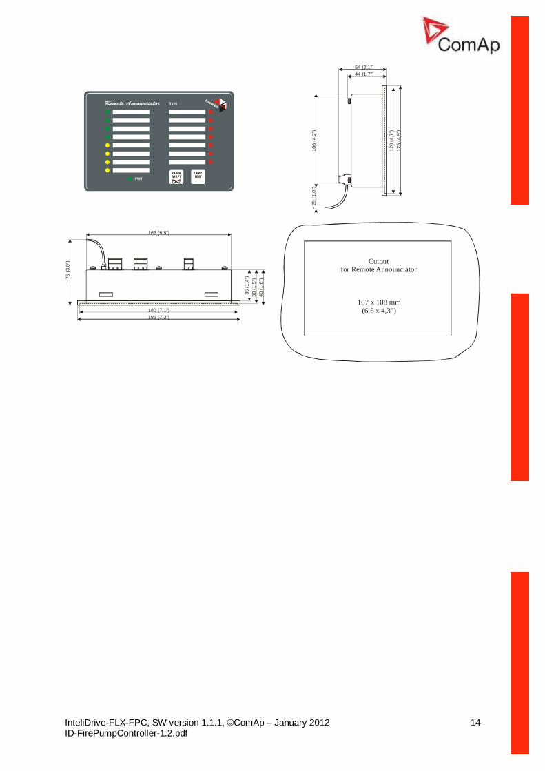
Remote announciator IGL-RA15 The remote announciator IGL-RA15 can be connected to the controller unit via CAN bus. Any of the binary outputs can be configured (using LiteEdit (3.0 or higher) software) to each LED diode on the RA15. The module (just one) can be also enabled and configured using LiteEdit software. Just Warning alarm is indicated when communication to RA15 is interrupted. See the documentation of IGL-RA15 for the technical and function description.
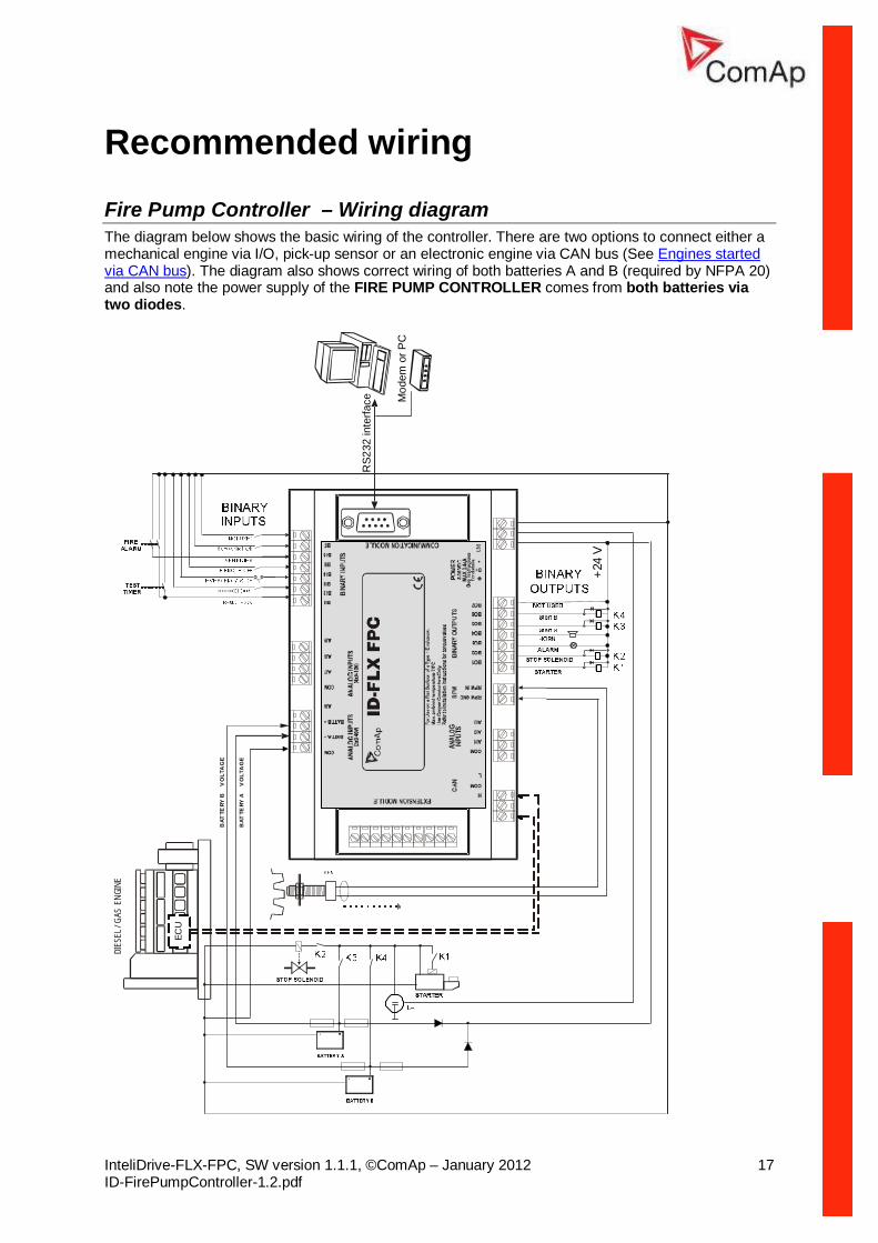
Fire Pump Controller – Wiring diagram The diagram below shows the basic wiring of the controller. There are two options to connect either a mechanical engine via I/O, pick-up sensor or an electronic engine via CAN bus (See Engines started via CAN bus). The diagram also shows correct wiring of both batteries A and B (required by NFPA 20) and also note the power supply of the FIRE PUMP CONTROLLER comes from both batteries via two diodes.
Wiring for binary and analog inputs must not be run with power cables. Analog and binary inputs should use shielded cables, especially when length >3m.
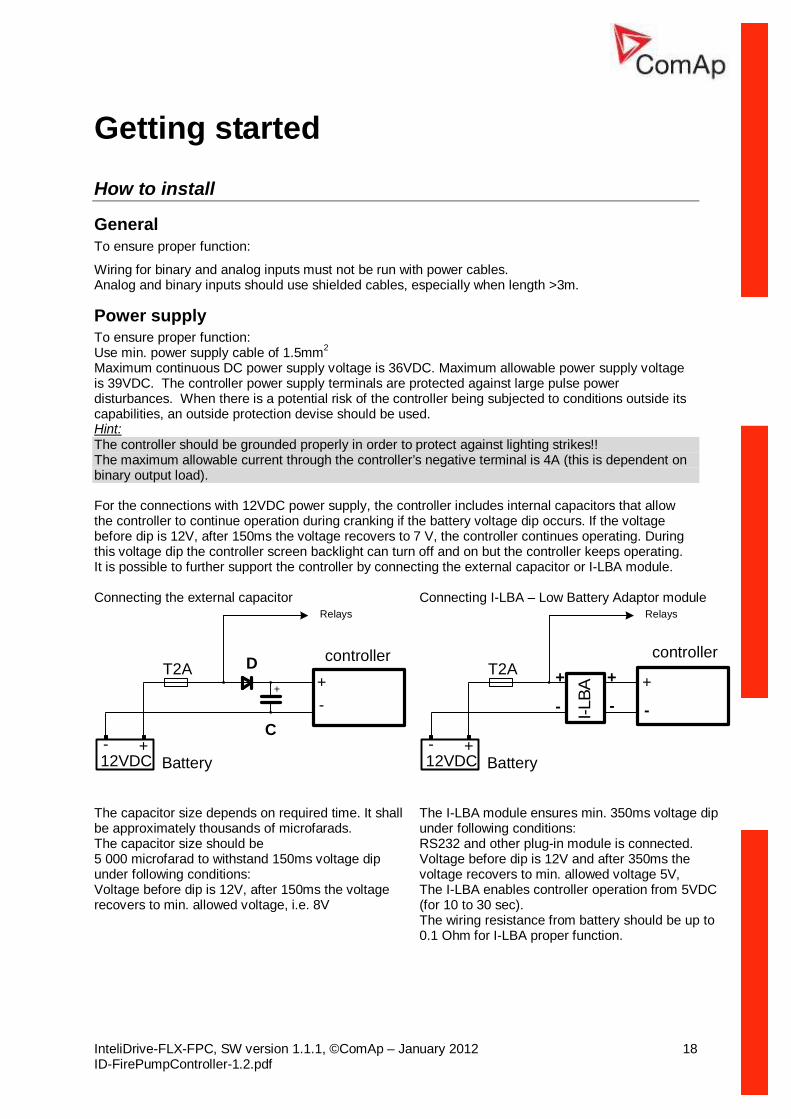
Power supply To ensure proper function: Use min. power supply cable of 1.5mm2 Maximum continuous DC power supply voltage is 36VDC. Maximum allowable power supply voltage is 39VDC. The controller power supply terminals are protected against large pulse power disturbances. When there is a potential risk of the controller being subjected to conditions outside its capabilities, an outside protection devise should be used. Hint: The controller should be grounded properly in order to protect against lighting strikes!! The maximum allowable current through the controller’s negative terminal is 4A (this is dependent on binary output load). For the connections with 12VDC power supply, the controller includes internal capacitors that allow the controller to continue operation during cranking if the battery voltage dip occurs. If the voltage before dip is 12V, after 150ms the voltage recovers to 7 V, the controller continues operating. During this voltage dip the controller screen backlight can turn off and on but the controller keeps operating. It is possible to further support the controller by connecting the external capacitor or I-LBA module. Connecting the external capacitor Connecting I-LBA – Low Battery Adaptor module
+-
12VDC+-
controllerT2A
Battery
+
D
C
Relays
+
-
12VDC+-
controllerT2A
Battery
Relays
I-LBA
+
-
+
-
The capacitor size depends on required time. It shall be approximately thousands of microfarads. The capacitor size should be 5 000 microfarad to withstand 150ms voltage dip under following conditions: Voltage before dip is 12V, after 150ms the voltage recovers to min. allowed voltage, i.e. 8V
The I-LBA module ensures min. 350ms voltage dip under following conditions: RS232 and other plug-in module is connected. Voltage before dip is 12V and after 350ms the voltage recovers to min. allowed voltage 5V, The I-LBA enables controller operation from 5VDC (for 10 to 30 sec). The wiring resistance from battery should be up to 0.1 Ohm for I-LBA proper function.
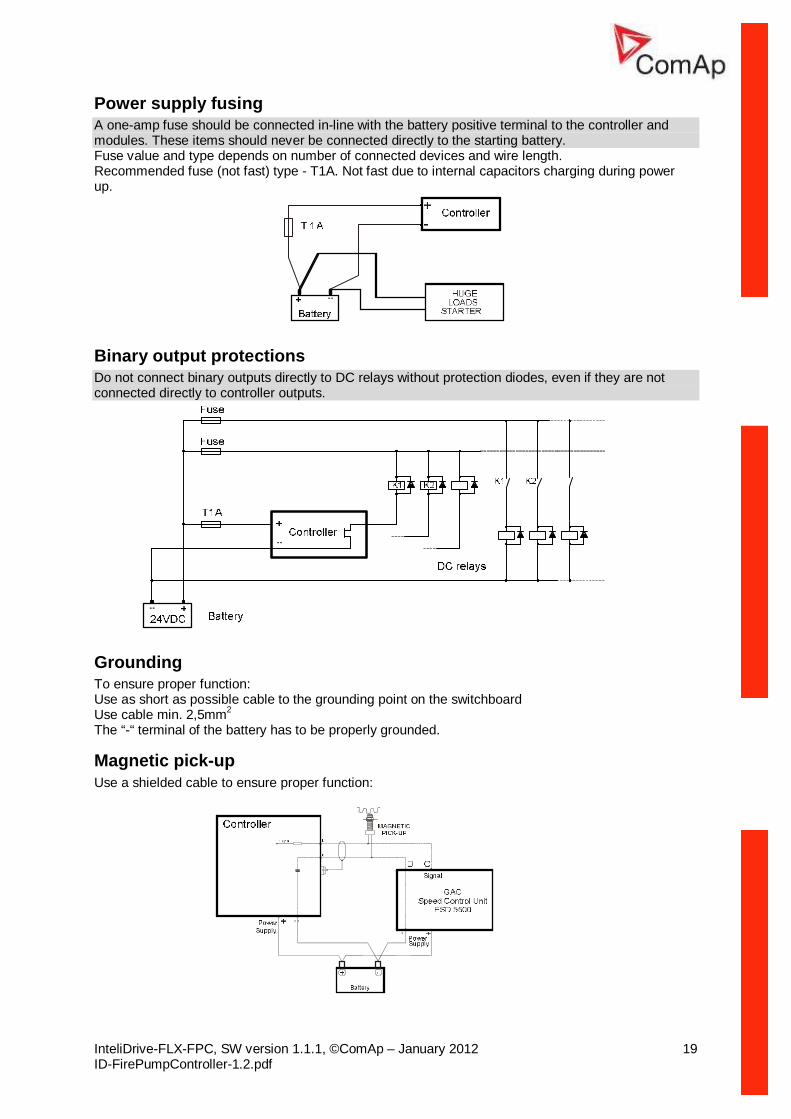
Power supply fusing A one-amp fuse should be connected in-line with the battery positive terminal to the controller and modules. These items should never be connected directly to the starting battery. Fuse value and type depends on number of connected devices and wire length. Recommended fuse (not fast) type - T1A. Not fast due to internal capacitors charging during power up.
Binary output protections Do not connect binary outputs directly to DC relays without protection diodes, even if they are not connected directly to controller outputs.
Grounding To ensure proper function: Use as short as possible cable to the grounding point on the switchboard Use cable min. 2,5mm2 The “-“ terminal of the battery has to be properly grounded.
Magnetic pick-up Use a shielded cable to ensure proper function:
Be aware of interference signal from Speed governor when one speed pick-up is used. If engine will not start:
- Check ground connection from pick-up to controllers, eventually disconnect ground connection to one of them
- Galvanic separate controller RPM input using ComAp separation transformer RPM-ISO (1:1) - Use separate pick-up for Speed governor and controller.
Analog inputs AI1, AI2, AI3 Resistive 0 – 2,5Kohm Fully configurable AI4, AI5 0 – 40,0 VDC Battery A, B voltage - Not configurable AI6, AI7, AI8, AI9 Voltage 0 – 10,000 VDC Configurable name and Sensor characteristics. AIO-AI1 – AIO-AI4 2,5Kohm / 4V / 20mA Plug-in module: Fully configurable
Configuration Each analog input can be configured by LiteEdit (3.0 or higher) software following way.
Analog input item LiteEdit Possibility Type Type Not used
Alarm Analog input isn’t used
Analog input name Name Up to 14 ASCII characters Config of input Config Analog
Binary Tri-state
Analog measuring in specified range. Binary: open/close - threshold 750 Ω for AIN1-AIN3 or 7,5V for AIN6-AIN9. Tri-state: open/close - threshold 750 Ω, Failure <10 Ω or > 2400 Ω Available for AIN1 –AIN3 only.
Physical dimension Dim bar,%,°C, … Up to 3 ASCII characters (Valid only for analog inputs)
Polarity Contact type
NC NO
Valid only for binary and three-state inputs Valid only for binary and three-state inputs
Over Overstep. Sensor fail does not activate protection.
Over+Fls Overstep and Sensor fail activates protection.
Under Under step. Sensor fail does not activate protection.
Protection direction Protection
Under+Fls Under step and Sensor fail activates protection.
Sensor characteristic Sensor Curve A Curve B Curve C
User curve A User curve B User curve C
Decimal points Dec 0, 1, 2 Number of decimal points (Valid only for analog inputs)
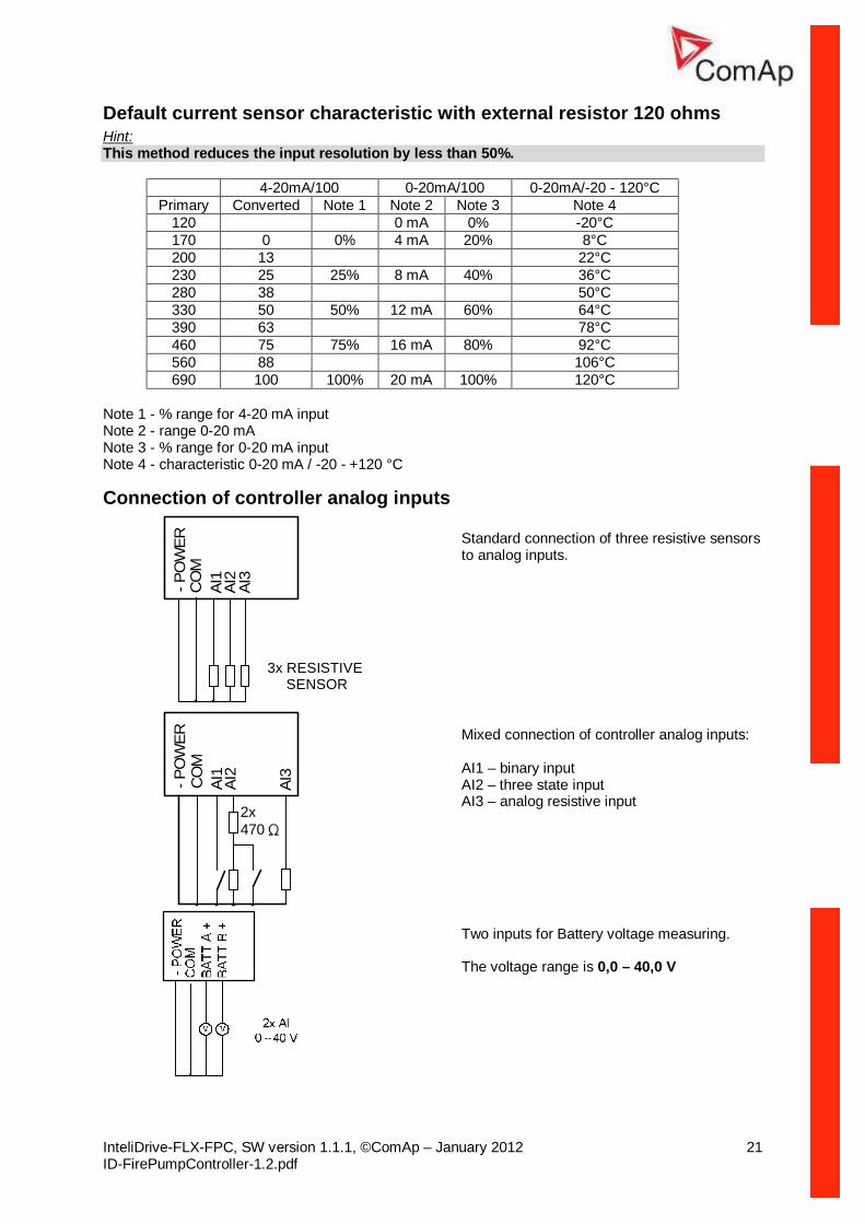
User Curves A, B, C are adjustable in LiteEdit (3.0 or higher) – use “Points” button.. Each Analog input has separate set points for two level alarm setting. Analog input alarm levels and delay adjust in Protection or Engine protection group. Hint: Current sensor can be connected to AI1, AI2, and AI3 resistive input when external resistor 120 ohms is connected between Aix and AI-COM. In such a case use following sensor characteristics.
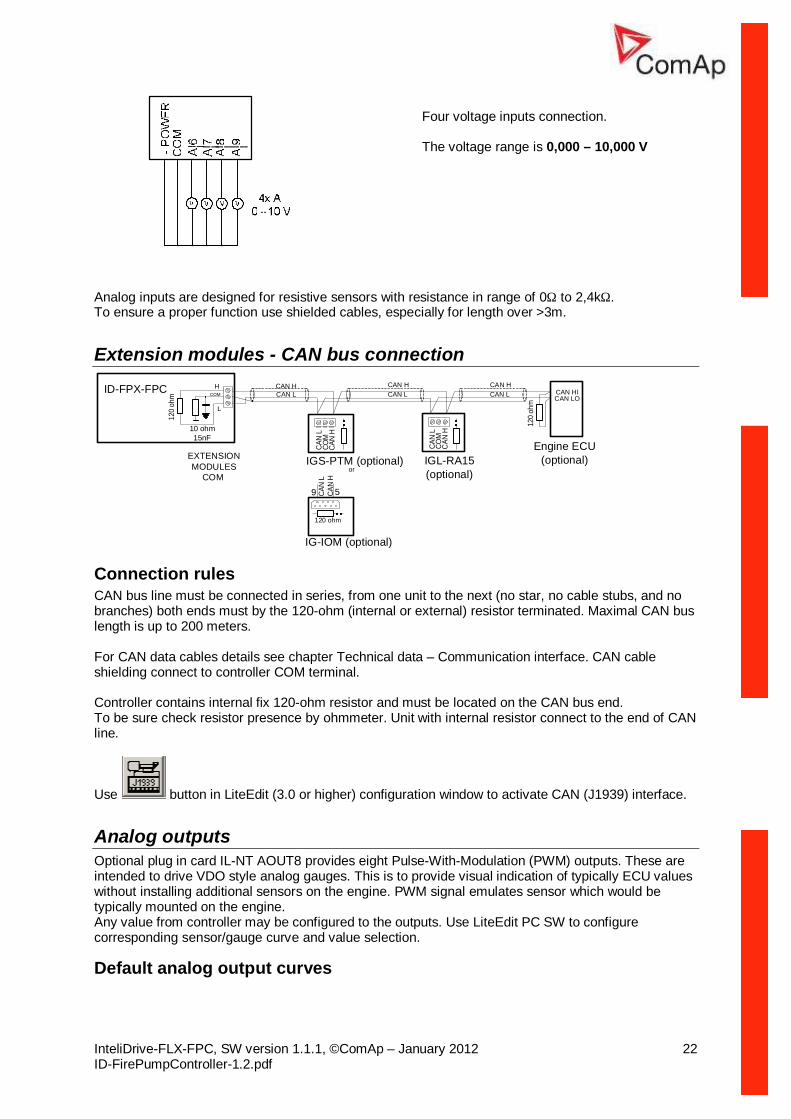
Four voltage inputs connection. The voltage range is 0,000 – 10,000 V
Analog inputs are designed for resistive sensors with resistance in range of 0Ω to 2,4kΩ. To ensure a proper function use shielded cables, especially for length over >3m.
Extension modules - CAN bus connection
EXTENSION MODULES
COM
CAN HCAN L
IGL-RA15 (optional)
CAN HCAN L
CAN HCAN L
H
L
or
120
ohm
CAN
L
CAN
HCO
M
IGS-PTM (optional)
CAN
L
CAN
HCO
M
IG-IOM (optional)
59 CAN
LCA
NH
120 ohm
CAN HICAN LO
120
ohm
10 ohm 15nF
COMID-FPX-FPC
Engine ECU(optional)
Connection rules CAN bus line must be connected in series, from one unit to the next (no star, no cable stubs, and no branches) both ends must by the 120-ohm (internal or external) resistor terminated. Maximal CAN bus length is up to 200 meters. For CAN data cables details see chapter Technical data – Communication interface. CAN cable shielding connect to controller COM terminal. Controller contains internal fix 120-ohm resistor and must be located on the CAN bus end. To be sure check resistor presence by ohmmeter. Unit with internal resistor connect to the end of CAN line.
Use button in LiteEdit (3.0 or higher) configuration window to activate CAN (J1939) interface.
Analog outputs Optional plug in card IL-NT AOUT8 provides eight Pulse-With-Modulation (PWM) outputs. These are intended to drive VDO style analog gauges. This is to provide visual indication of typically ECU values without installing additional sensors on the engine. PWM signal emulates sensor which would be typically mounted on the engine. Any value from controller may be configured to the outputs. Use LiteEdit PC SW to configure corresponding sensor/gauge curve and value selection.
Inputs and outputs Hint: Any Binary input or output can be configured to any controller terminal or changed to different function by LiteEdit (3.0 or higher) software. There is fix 1 sec delay when any binary input is configured as protection.
Binary inputs FIRE PUMP CONTROLLER - default
BI1 Rem start/stop
BI3 Emergency stop
BI4 Remote OFF
BI5 Sprinkler
BI6 RemControlLock
BI7 Not Used
Binary inputs – list
Not used Binary input has no function. Use this configuration when Binary input is not connected.
Rem start/stop External request for engine run. AUT mode only. Hint: Designed to start the engine while the fire when the signal which gives the information about the fire is a binary one.
Emergency stop If the input is opened, shut down is immediately activated. Input is inverted (normally closed) in default configuration. Hint: In case of controller hardware or software fail, safe stop of the engine doesn’t have to be ensured. To back-up the Emergency stop function it is recommended to connect separate circuit for disconnection of Fuel solenoid and Starter signals.
Sprinkler If the input is closed all alarms are disabled except the binary input EMERGENCY STOP and "engine overspeed protection".
• all controller alarms are detected, • controller front panel RED LED blinks or lights, • Alarm is recorded on the controller alarm list screen, • BUT engine remains running.
Hint: Warning SprinklActive is indicated in the Alarm list if sprinkler mode active to inform the operator that the engine is not protected.
Access lock If the input is closed, no setpoints can be adjusted from controller front panel and engine mode (OFF-TEST-AUT) cannot be changed. Hint: Access lock does not protect setpoints and mode changing from LiteEdit. To avoid unqualified changes the selected setpoints can be password protected.
Remote OFF If closed, controller is switched to OFF mode (there are four modes OFF-TEST-AUT). When opens controller is switched back to previous mode. Hint: This binary input should be connected to schedule timer switch, to avoid start of engine.
Remote TEST If the input is active, TEST mode is forced to the controller independently on the position of the MODE selector.
Remote AUT If the input is active, AUT mode is forced to the controller independently on the position of the MODE selector. If another of „remote“ inputs is active, then the REMOTE AUT input has the lowest priority.
RemControlLock If the input is active, setpoints writing or command sending from the external terminal is disabled.
Emerg. manual If the input is activated the controller behaves like when switched to OFF mode and opens all binary outputs. There is one exception – STOP SOLENOID doesn’t activate on this transition. Detection of "running" engine and subsequent alarm message "Sd Stop fail" is blocked. The controller shows “Emerg Man” state and the engine can not be started. After the input is open again, the controller recovers to previous state and behaves according to the actual situation. Function is active in any controller mode.
StartButton Binary input has the same function as Start button on the controller front panel. It is active in TEST mode only.
StopButton Binary input has the same function as Stop button on the controller front panel. It is active in TEST mode only.
FaultResButton Binary input has the same function as Fault reset button on the controller front panel.
HornResButton Binary input has the same function as Horn reset button on the controller front panel.
Nominal/Idle Input works in TEST mode only. Active Nominal/Idle input activates binary output Idle/Nominal and sends either Speed request = 0 % (e.g. Standard J1939) or active IDLE command to the ECU (e.g. to Volvo EMS).
Active input opens the binary output Ready to Load during the engine “Running” state. Ready to Load can be closed back (if other conditions are fulfilled – see the Ready to Load binary output description) if Nominal/Idle opens.
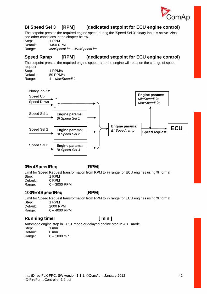
Speed Up If the input is active, the Speed Request may increase the engine speed value. The Speed Request value may also depend on the conditions which are described in the chapter below.
Speed Down If the input is active, the Speed Request may decrease the engine speed value. The Speed Request value may also depend on the conditions which are described in the chapter below. SpeedUp/Down binary inputs are active only when Regulator: LAI SpdSelect = OFF.
Speed Sel 1 If the input is active, the Speed request = Engine params: BI Speed Sel 1 setpoint. The function is affected by Engine params: RetToSpeedAdj. RetToSpeed
Speed Sel 2 If the input is active, the Engine params: BI Speed Sel 2 setpoint may give the engine speed value for Speed request to an ECU engine. The Speed Request value may also depend on the conditions which are described in the chapter below.
Speed Sel 3 If the input is active, the Engine params: BI Speed Sel 3 setpoint may give the engine speed value for Speed request to an ECU engine. The Speed Request value may also depend on the conditions which are described in the chapter below. Hint: Engine params: RetToSpeedAdj = DISABLED … Speed request is set by BI Speed Sel1, ..2, ..3 edge (button press). i.e. input can be opened and Speed request stay constant. Engine params: RetToSpeedAdj = ENABLED … Speed request is set by BI Speed Sel1, ..2, ..3 level (switch) i.e. when input is opened Speed request go back to Engine params: ECU SpeedAdj level. SpeedSel1, ..2, ..3 binary inputs are active only when Regulator: LAI SpdSelect = OFF. When more binary inputs are active at the same time, e.g. all binary inputs: ‘Speed Sel1’, ‘Speed Sel2’, ‘Speed Sel3’ then requested speed is given by Engine params: BI Speed Sel 1 (lowest index) setpoint.
Lang selection Switches display texts between two languages.
Starter The closed output energizes the starter motor. The output always closes with 1 second delay after closing of the binary output Start A or Start B. The Starter output opens when:
• the Starting RPM is reached or • the Starting POil is reached or • D+ input activated • maximum time of cranking is exceeded or • request to stop comes up
Hint: The binary output Starter stays closed for 5 seconds even if engine speed appears to be zero. If there are no RPM during this time, controller opens Starter output, waits for Engine params: CrnkFail pause and tries to start again.
Start A The closed output energizes the starter motor from battery A (also see Start-Stop sequence table and a sequence example of a fire start). The Batt A output always opens 4 seconds after each finished but unsuccessful cranking attempt and never closes together with Batt B. When the start from battery A has been successful the output Batt A stays closed until stop of the engine.
Start B The closed output energizes the starter motor from battery B (also see Start-Stop sequence table and a sequence example of a fire start). The Batt B output always opens 4 seconds after each finished but unsuccessful cranking attempt and never closes together with Batt A. When the start from battery B has been successful the output Batt B stays closed until stop of the engine.
Fuel solenoid Closed output opens the fuel solenoid and enables the engine start. The output always closes together with the Batt A or Batt B binary output. The output opens if:
• EMERGENCY STOP comes or • Cooled engine is stopped or • in pause between repeated starts
Stop solenoid The closed output energizes stop solenoid to stop the engine. The output is active at least for Stop time, if the stop lasts longer; it stays active until all symptoms say the engine is stopped. The engine is stopped if:
RPM < 2 and Oil pressure < Engine params: StartingPoil.
Hint: The engine can be started anytime, if all symptoms say the engine is steady regardless of the fact the Stop solenoid can still be active (in that case it is deactivated before cranking).
Stop Pulse Output is active for 1 second after Stop solenoid output activation. This signal is sent to ECU in case of engine stop request.
Ignition The output closes after reaching value of CrankRPM, fixed 30RPM. Opens after stopping of the engine or in pause during repeated start.
Prestart The output closes prior to the engine start (Prestart) and opens when Starting RPM speed is reached. During repeated crank attempts the output is closed too. The output could be used for pre-glow, pre-heat or prelubrication.
Cooling pump The output closes when engine starts and opens Engine params: AfterCool time after stop of the engine.
Idle/Nominal The output either follows the Nominal/Idle binary input in TEST mode or follows the engine state in AUT mode:
The output Idle/Nominal closes after the timer Idle time elapses. The Idle time counter starts to countdown when Start speed reached. The Underspeed protection is not evaluated during idle period. A Start fail protection occurs if the RPM drop below 2RPM during idle state.
Air valves Output closes together with Prestart and opens after the engine is stopped. Stopped engine conditions: RPM = 0, Engine params: Starting POil, D+ (when enabled).
Alarm The output closes if:
• any warning or shutdown comes up or • the engine malfunctions
The output opens if • FAULT RESET is pressed
The output closes again if a new fault comes up.
Horn The output closes if:
• any warning or shutdown comes up or • the engine malfunctions
The output opens if: • FAULT RESET is pressed or • HORN RESET is pressed or • Max time of HORN is exceeded (Horn timeout)
The output closes again if a new fault comes up.
Wrn AnImAIO1..4 Output closes if warning alarm on the appropriate IL-NT-AIO analog input activates. The output opens, if
• alarm is not active and • FAULT RESET is pressed
Sd AnImAIO1..4 Output closes if shutdown alarm on the appropriate IL-NT-AIO analog input activates. The output opens, if
• alarm is not active and FAULT RESET is pressed
Ready The output is closed if following conditions are fulfilled:
• Engine is not running and • No Shut down or Slow stop alarm is active • Controller is not in OFF mode
Ready to load The output is closed if engine is running and no alarm is active - it is possible to close load. The output opens when Wrn underspeed protection is active and during cooling state.
Running Output closes if the engine is in Running state.
Cooling The output closes when engine is in Cooling state.
Fault Reset One second pulse as echo for panel Fault reset button.
ChrgAlternFail Output closes if engine is running and D+ input not energized. The output opens, if
• alarm is not active and • FAULT RESET is pressed
Hint: Threshold level for D+ input is 80% supply voltage.
Stop failed Output closes when the engine has to be stopped, but speed, frequency, or voltage or oil pressure is detected. This protection goes active 60s after stop command. The output opens, if
• alarm is not active and • FAULT RESET is pressed
Overspeed Output closes if the engine over speed alarm activates. The output opens, if
• alarm is not active and • FAULT RESET is pressed
Underspeed Output closes if the engine “Sd Underspeed” alarm activates i.e. when RPM is below the Engine params: Starting RPM limit. The output opens, if
• alarm is not active and • FAULT RESET is pressed
Start failed Output closes after the engine start-up fails. The output opens, if
• alarm is not active and • FAULT RESET is pressed
Battery flat Output closes when controller performs reset during start procedure (probably due to weak battery). The output opens, if
• alarm is not active and • FAULT RESET is pressed
Common Wrn Output closes when any warning alarm appears. The output opens, if
• No warning alarm is active and • FAULT RESET is pressed
Common Sd Output closes when any shut-down alarm appears. The output opens, if
• No sd alarm is active and • FAULT RESET is pressed
In case the assigned binary input is configured to alarm type, then the output closes when the alarm activates. It opens if
• alarm is not active and • FAULT RESET is pressed
CtrlHeartBeat Output signalizes watchdog reset. In a healthy state it blinks at 500ms rate. When watchdog reset occurs, it stops blinking.
BIO8 1..8 - Status The outputs give information about the assigned binary input. In case the assigned binary input is configured to alarm type, then the output closes when the alarm activates. It opens if
• alarm is not active and • FAULT RESET is pressed
In case the assigned binary input is configured to any control function, the output propagates the state of the input.
ECU CommOK If the ECU is not communicating and all values from ECU show #### the output is not active. If the ECU communicates the output is active.
ECU CommError The output is an inversion of binary output ECU CommOK, i.e. the output is closed when ECU is not communicating and all values from ECU show #####.
ECU YellowLamp The output copies warning information from ECU.
ECU RedLamp The output copies shutdown information from ECU.
ECU PwrRelay The output closes at the beginning of prestart and opens if the engine shall be stopped.
Timer1 Output activates when Timer1 is active. Simultaneously, engine is started when is in AUT mode.
Timer2 Output activates when Timer2 is active
Glow plugs The output closes prior to the engine start (Prestart) and opens when Starting RPM speed is reached. During repeated crank attempts the output is opened.
V BATT A Fail Indication of Battery voltage is out of limits Engine protect: Batt A over V, Batt A under V, Batt A del.
V BATT B Fail Indication of Battery voltage is out of limits Engine protect: Batt B over V, Batt B under V, Batt B del.
V batt failed Indication of Battery voltage A or B is out of limits
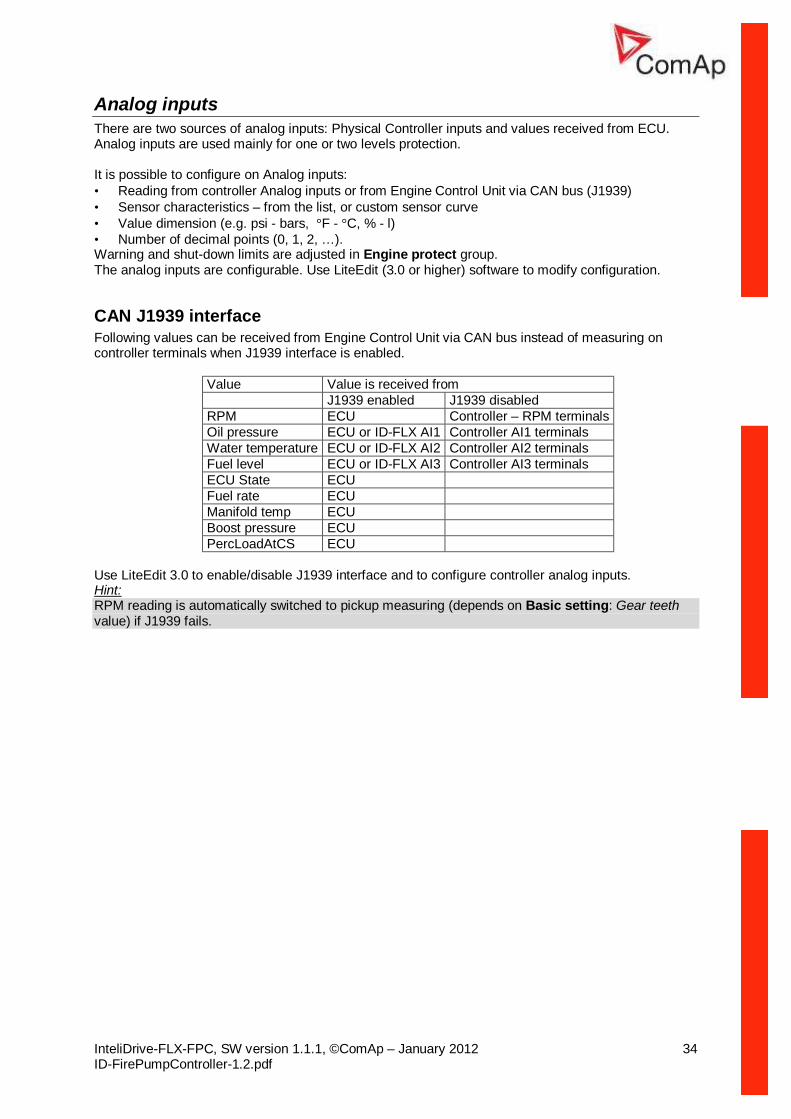
Analog inputs There are two sources of analog inputs: Physical Controller inputs and values received from ECU. Analog inputs are used mainly for one or two levels protection. It is possible to configure on Analog inputs: • Reading from controller Analog inputs or from Engine Control Unit via CAN bus (J1939) • Sensor characteristics – from the list, or custom sensor curve • Value dimension (e.g. psi - bars, °F - °C, % - l) • Number of decimal points (0, 1, 2, …). Warning and shut-down limits are adjusted in Engine protect group. The analog inputs are configurable. Use LiteEdit (3.0 or higher) software to modify configuration.
CAN J1939 interface Following values can be received from Engine Control Unit via CAN bus instead of measuring on controller terminals when J1939 interface is enabled.
Value Value is received from J1939 enabled J1939 disabled RPM ECU Controller – RPM terminals Oil pressure ECU or ID-FLX AI1 Controller AI1 terminals Water temperature ECU or ID-FLX AI2 Controller AI2 terminals Fuel level ECU or ID-FLX AI3 Controller AI3 terminals ECU State ECU Fuel rate ECU Manifold temp ECU Boost pressure ECU PercLoadAtCS ECU
Use LiteEdit 3.0 to enable/disable J1939 interface and to configure controller analog inputs. Hint: RPM reading is automatically switched to pickup measuring (depends on Basic setting: Gear teeth value) if J1939 fails.
EnterPassword Password is a four-digit number. Password enables change of relevant protected set points Use ↑ or ↓ keys to set and ENTER key to enter the password. There are 3 levels of passwords. Knowledge of higher password lets you to change setpoint protected by lower password.
ChangePassword Use ↑ or ↓ keys to set and ENTER key to change the password. Hint: At first the Password has to be entered before the new Password can be changed.
Basic settings
Engine name User defined name, used for engine – controller identification at remote phone or mobile connection. Engine name is max 14 characters long and have to be entered using LiteEdit (3.0 or higher) software.
Gear teeth [-] Number of teeth on the engine gear for the pick-up sensor. The setpoint is ignored when ECU is configured. Step: 1 Range: 0 – 500
RPMbyWterminal [-] The value of this setpoint multiplies the speed value obtained from the controller input RPM. Step: 0.01 Range: 0.5 – 2 Hint: The default value is and must be 1, when the classical pick-up speed sensor is used to measure the engine speed. The setpoint is usefull when the engine does not have the speed sensor and the speed is measured by the W terminal of the charging alternator. The setpoint allows tuning the ratio between the frequency and the RPM value which can not to correspond to the entire values of teeth numbers (because of the different non-integral ratio of the engine and alternator pulleys).
RPM Source [PICKUP, AIO AIN1, AIO AIN2, AIO AIN3, AIO AIN4] Switch for actual engine speed measuring. Pickup: The settings uses RPM input of the controller as a source of Engine Speed measurement AIO-AIN1 – AIO-AIN4: The settings uses one of analog inputs of the controller (AIN1 – AIN4) and its
corresponding sensor characteristics as a source of Engine Speed measurement
ControllerMode [ OFF, TEST, AUT] Equivalent to Controller mode changes by MODE→ or ←MODE buttons. Hint: Controller Mode change can be separately password protected.
FltResGoToMAN [ENABLED/DISABLED] DISABLED: Controller stays in AUT mode after Fault reset . ENABLED: Automatic switch from AUT (or TEST) to TEST mode after Fault reset to avoid
automatic engine start. This function is active for Shut down protection only.
DispBaklightTO [min] Timeout after which the display backlight is switched off. Step: 1 min Range: 0 – 60 min Default value: 0 … means that the display lights all the time
Comms Settings
Contr. addr (1 .. 32) [-] Controller identification number. It is possible to set controller address different from the default value (1) so that more ID-Lite controllers can be interconnected (via RS485) and accessed e.g. from Modbus terminal. Hint: When opening connection to the controller its address has to correspond with the setting in PC tool. From LiteEdit it is only possible to connect to controllers with address 1.
COM1 Mode [DIRECT/MODEM/MODBUS/ECU LINK] Communication protocol switch for the COM1 channel. DIRECT: LiteEdit communication protocol via direct cable or AirGate, WebSupervisor
communication protocol via AirGate. MODEM: LiteEdit communication protocol via modem. MODBUS: Modbus protocol. See detailed description in InteliCommunication guide. ECU LINK: Protocol for communication with Cummins engines via Modbus. Hint: For details on communication speed and other technical parameters please see chapter Technical Data. For detail description see chapter Modbus protocol.
COM2 Mode [DIRECT/MODBUS/ECU LINK] Communication protocol switch for the COM2 channel, if dual communication module is plugged in. DIRECT: LiteEdit communication protocol via direct cable. MODBUS: Modbus protocol. See detailed description in InteliCommunication guide. ECU LINK: Protocol for communication with Cummins engines via Modbus. Hint: For details on communication speed and other technical parameters please see chapter Technical Data. For detail description of communication possibilities see actual Inteli Communication Guide xxx.pdf - chapter Modbus protocol and others.
ModemIniString If your modem needs some additional initialization AT commands (i.e. because of national telephony network differences), it can be entered here. Otherwise leave this setpoint blank.
ModbusComSpeed [9600,19200, 38400, 57600] If the Modbus mode is selected on COM1 or COM2 channels, the Modbus communication speed in bps can be adjusted here.
IBLite IP Addr IP address of IB-Lite module
IBLite NetMask IB-Lite network mask
IBLite GateIP IP address of gateway for IB-Lite
ComAp Port Port for ComAp communication over IB-Lite or IL-NT-GPRS module
APN Name Name of APN access point for GPRS network. Hint: This information shall provide your GSM/GPRS operator.
APN UserName User name for APN access point. Hint: This information shall provide your GSM/GPRS operator.
APN UserPass User password for APN access point. Hint: This information shall provide your GSM/GPRS operator.
AirGate [ENABLED / DISABLED] The option DISABLED blocs the function of AirGate. This allows the module IL-IB to work (when connected).
AirGate IP AirGate Address. The default value is „airgate.comap.cz“. Hint: To reduce the data traffic over GPRS network you can set in setpoint group „Comms Settings“ the parameter „AirGate IP“ = 80.95.108.26. This will save significant data amount needed for translation of AirGate server IP address. In case of changing the server IP address this settings has to be updated or returned to default „airgate.comap.cz“. Warning: All manipulations with IL-NT-GPRS module have to be done with DC power supply switched off. Module can be only powered on while plugged in the controller and together with controller!
SMTP UserName User name or name of e-mail account for verification of email sender on SMTP server. If parameter left empty, no verification is expected. Works for IB-Lite only.
SMTP UserPass User password of e-mail account for verification of e-mail sender on SMTP server. If parameter left empty, no verification is expected. Works for IB-Lite only.
SMTP Server IP IP address of SMTP server. Works for IB-Lite only.
Contr MailBox E-mail address used as “Sender” of alarm e-mails from IB-Lite. Hint: If SMTP server requires verification of sender, e-mail address has to be registered to SMTP server and setpoints “SMTP UserName” and “SMTP UserPass” has to be set to correct values.
Time Zone List of time zones used for time reference.
DNS IP Address IP address of Domain Name Server.
Engine params
Starting RPM [%] “Firing” speed when controller stops cranking (starter goes OFF). Starting speed is limit for Sd Underspeed protection activated 5 sec (fix time) after RPM goes above this limit during the engine starting procedure. Step: 1% of Nominal RPM Range: 5 – 50 %
Starting POil [Bar] When reached controller stops cranking (starter goes OFF). Step: 0,1 Bar Range: 0,0 – 10,0 Bar Hint: There are three conditions for stop cranking: Starting RPM, StartingPOil and D+ (when enabled). Starter goes off when any of these conditions is valid.
Prestart time [s] Time of closing of the PRE-START output prior to the engine start. Set to zero if you want to leave the output PRE-START open. Step: 1s Range: 0 – 600 s
MaxCrank time [s] Maximum time limit of cranking. Step: 1s Range: 1 – 60 s
CrnkFail pause [s] Pause between crank attempts. Step: 1s Range: 5 – 60 s
Crank attempts [-] Max number of crank attempts. Step: 1 Range: 1 – 10
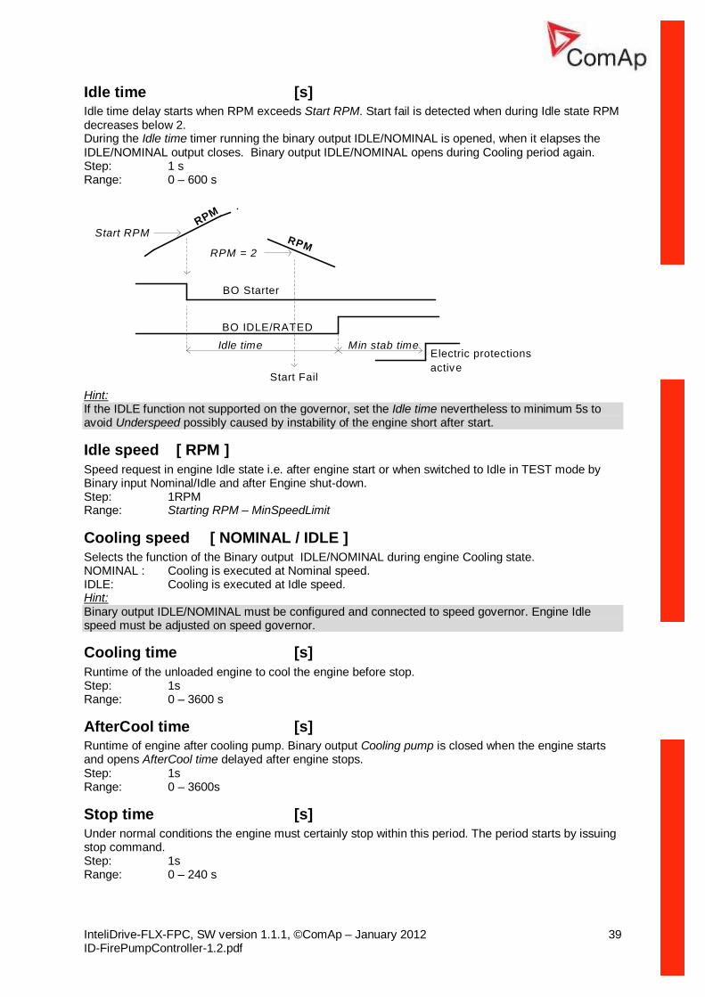
Idle time [s] Idle time delay starts when RPM exceeds Start RPM. Start fail is detected when during Idle state RPM decreases below 2. During the Idle time timer running the binary output IDLE/NOMINAL is opened, when it elapses the IDLE/NOMINAL output closes. Binary output IDLE/NOMINAL opens during Cooling period again. Step: 1 s Range: 0 – 600 s
Start RPMRPM
BO Starter
BO IDLE/RATED
RPM = 2RPM
Start Fail
Idle time Min stab timeElectric protectionsactive
Hint: If the IDLE function not supported on the governor, set the Idle time nevertheless to minimum 5s to avoid Underspeed possibly caused by instability of the engine short after start.
Idle speed [ RPM ] Speed request in engine Idle state i.e. after engine start or when switched to Idle in TEST mode by Binary input Nominal/Idle and after Engine shut-down. Step: 1RPM Range: Starting RPM – MinSpeedLimit
Cooling speed [ NOMINAL / IDLE ] Selects the function of the Binary output IDLE/NOMINAL during engine Cooling state. NOMINAL : Cooling is executed at Nominal speed. IDLE: Cooling is executed at Idle speed. Hint: Binary output IDLE/NOMINAL must be configured and connected to speed governor. Engine Idle speed must be adjusted on speed governor.
Cooling time [s] Runtime of the unloaded engine to cool the engine before stop. Step: 1s Range: 0 – 3600 s
AfterCool time [s] Runtime of engine after cooling pump. Binary output Cooling pump is closed when the engine starts and opens AfterCool time delayed after engine stops. Step: 1s Range: 0 – 3600s
Stop time [s] Under normal conditions the engine must certainly stop within this period. The period starts by issuing stop command. Step: 1s Range: 0 – 240 s
Hint: Stop of engine is detected when all following conditions are met: RPM <2, Oil pressure < StartingPOil and D+ input isn’t active. Stop fail is detected when there is difference between those conditions.
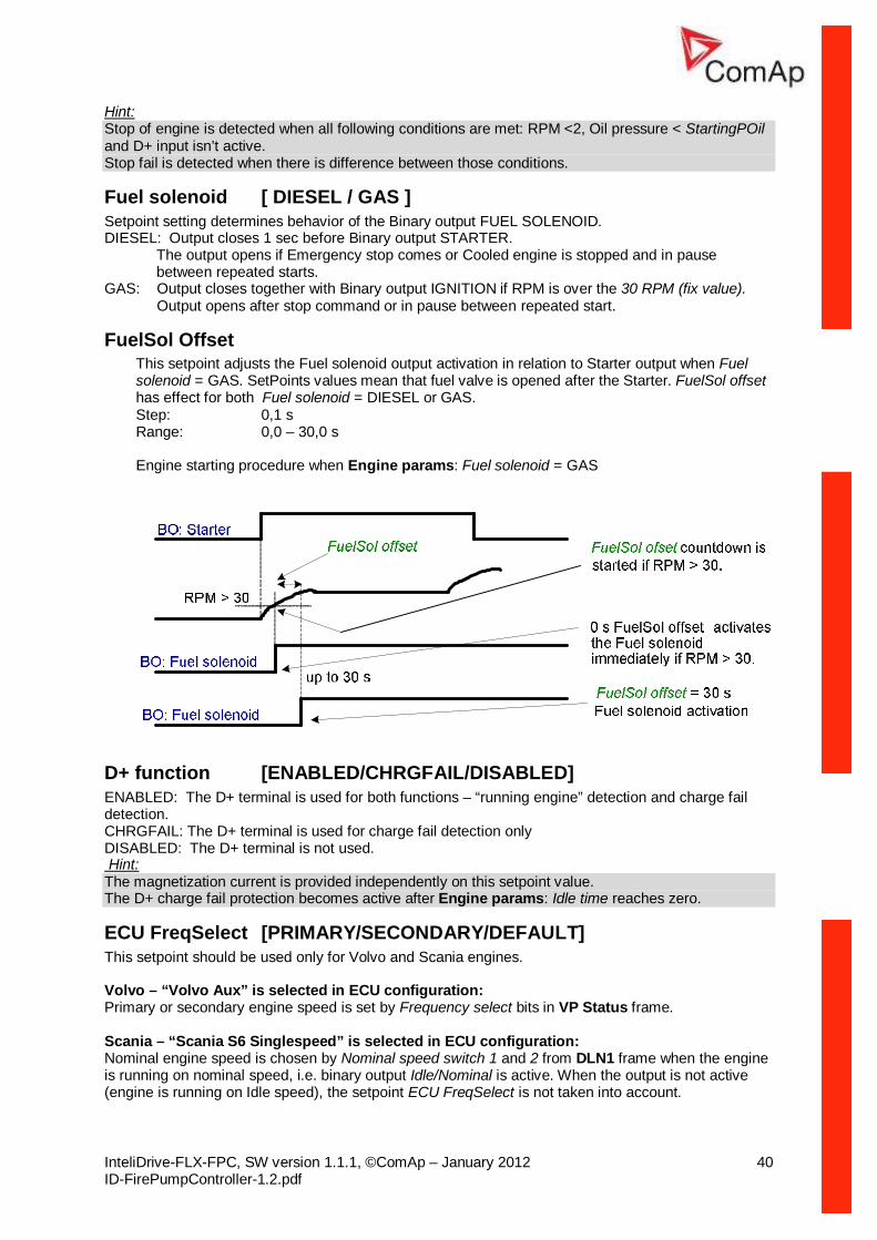
Fuel solenoid [ DIESEL / GAS ] Setpoint setting determines behavior of the Binary output FUEL SOLENOID. DIESEL: Output closes 1 sec before Binary output STARTER.
The output opens if Emergency stop comes or Cooled engine is stopped and in pause between repeated starts.
GAS: Output closes together with Binary output IGNITION if RPM is over the 30 RPM (fix value). Output opens after stop command or in pause between repeated start.
FuelSol Offset This setpoint adjusts the Fuel solenoid output activation in relation to Starter output when Fuel solenoid = GAS. SetPoints values mean that fuel valve is opened after the Starter. FuelSol offset has effect for both Fuel solenoid = DIESEL or GAS. Step: 0,1 s Range: 0,0 – 30,0 s Engine starting procedure when Engine params: Fuel solenoid = GAS
D+ function [ENABLED/CHRGFAIL/DISABLED] ENABLED: The D+ terminal is used for both functions – “running engine” detection and charge fail detection. CHRGFAIL: The D+ terminal is used for charge fail detection only DISABLED: The D+ terminal is not used. Hint: The magnetization current is provided independently on this setpoint value. The D+ charge fail protection becomes active after Engine params: Idle time reaches zero.
ECU FreqSelect [PRIMARY/SECONDARY/DEFAULT] This setpoint should be used only for Volvo and Scania engines. Volvo – “Volvo Aux” is selected in ECU configuration: Primary or secondary engine speed is set by Frequency select bits in VP Status frame. Scania – “Scania S6 Singlespeed” is selected in ECU configuration: Nominal engine speed is chosen by Nominal speed switch 1 and 2 from DLN1 frame when the engine is running on nominal speed, i.e. binary output Idle/Nominal is active. When the output is not active (engine is running on Idle speed), the setpoint ECU FreqSelect is not taken into account.
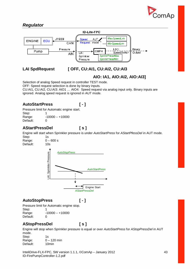
ECU Control [ ENABLED, STARTSTOP, DISABLED ] The setpoint enables adjustment of the electronic engine control by following settings: ENABLED – there is a full available control of an electronic engine given by the setting of the ECU unit of the engine, i.e. Start request, Stop request, Speed request are enabled if available STARTSTOP – there is a limited control of an electronic engine reduced to both Start request and Stop request. The Speed request is blocked. DISABLED – a control of an electronic engine is fully blocked and the ID-Lite can only monitor the values of an electronic engine. Default: ENABLED
ECU SpeedAdj [ RPM ] (dedicated setpoint for ECU engine control) Enables to adjust engine speed in ECU via CAN bus. Nominal speed corresponds to 50%. This setpoint should be used only for Volvo Penta and Scania engines. It has no effect on other engine brands. Step: 1 RPM Default: 1500 RPM Range: MinSpeedLim – MaxSpeedLim
RetToSpeedAdj [ ENABLED, DISABLED ] Selection between LBI Speed selection1, ..2, ..3 behavior. DISABLED: Speed request is set by LBI Speed selection1, ..2, ..3 (see corresponding setpoints) by rising edge (button, no switch) – i.e. Speed request stay constant after the input is opened and can be changed by BI Speed Up and Speed Down. ENABLED: Speed request goes to ECU SpeedAdj when the LBI Speed selection1, ..2, ..3 is opened. Speed request can be changed by Binary inputs Speed Up and Speed Down when LBI Speed selection 1, ..2, ..3 is closed.
MinSpeedLim [RPM] (dedicated setpoint for ECU engine control) The setpoint presets the minimum engine speed in the “Running” operation mode. Also see other conditions in the chapter below. Step: 1 RPM Default: 1200 RPM Range: Starting RPM – MaxSpeedLim
MaxSpeedLim [RPM] (dedicated setpoint for ECU engine control) The setpoint presets the maximum engine speed in the “Running” operation mode. Also see other conditions in the chapter below. Step: 1 RPM Default: 2700 RPM Range: MinSpeedLim – 4000 RPM
BI Speed Sel 1 [RPM] (dedicated setpoint for ECU engine control) The setpoint presets the required engine speed during the ‘Speed Sel 1’ binary input is active. Also see other conditions in the chapter below. Step: 1 RPM Default: 1250 RPM Range: MinSpeedLim – MaxSpeedLim
BI Speed Sel 2 [RPM] (dedicated setpoint for ECU engine control) The setpoint presets the required engine speed during the ‘Speed Sel 2’ binary input is active. Also see other conditions in the chapter below. Step: 1 RPM Default: 1300 RPM Range: MinSpeedLim – MaxSpeedLim
BI Speed Sel 3 [RPM] (dedicated setpoint for ECU engine control) The setpoint presets the required engine speed during the ‘Speed Sel 3’ binary input is active. Also see other conditions in the chapter below. Step: 1 RPM Default: 1450 RPM Range: MinSpeedLim – MaxSpeedLim
Speed Ramp [RPM] (dedicated setpoint for ECU engine control) The setpoint presets the required engine speed ramp the engine will react on the change of speed request Step: 1 RPM/s Default: 50 RPM/s Range: 1 – MaxSpeedLim
0%ofSpeedReq [RPM] Limit for Speed Request transformation from RPM to % range for ECU engines using % format. Step: 1 RPM Default: 0 RPM Range: 0 – 3000 RPM
100%ofSpeedReq [RPM] Limit for Speed Request transformation from RPM to % range for ECU engines using % format. Step: 1 RPM Default: 2000 RPM Range: 0 – 4000 RPM
Running timer [ min ] Automatic engine stop in TEST mode or delayed engine stop in AUT mode. Step: 1 min Default: 0 min Range: 0 – 1000 min
AIO: IA1, AIO:AI2, AIO:AI3] Selection of analog Speed request in controller TEST mode. OFF: Speed request selection is done by binary inputs. CU:AI1, CU:AI2, CU:AI3: AIO1 … AIO4: Speed request via analog input only. Binary inputs are ignored. Analog speed request is ignored in AUT mode.
AStartPressDel [ s ] Engine will start when Sprinkler pressure is under AutoStartPress for AStartPfessDel in AUT mode. Step: 1s Range: 0 – 600 s Default: 10s
AStopPressDel [ s ] Engine will stop when Sprinkler pressure is equal or over AutoStartPress for AStopPressDel in AUT mode. Step: 1s Range: 0 – 120 min Default: 10min
AIO: IA1, AIO:AI2, AIO:AI3 ] Input for Automatic engine start based on pressure.
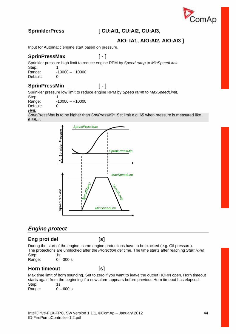
SprinPressMax [ - ] Sprinkler pressure high limit to reduce engine RPM by Speed ramp to MinSpeedLimit. Step: 1 Range: -10000 – +10000 Default: 0
SprinPressMin [ - ] Sprinkler pressure low limit to reduce engine RPM by Speed ramp to MaxSpeedLimit. Step: 1 Range: -10000 – +10000 Default: 0 Hint: SprinPressMax is to be higher than SpriPressMin. Set limit e.g. 65 when pressure is measured like 6,5Bar.
SprinkPressMin
SprinkPressMax
MaxSpeedLim
MinSpeedLim
SpeedRamp
Engine protect
Eng prot del [s] During the start of the engine, some engine protections have to be blocked (e.g. Oil pressure). The protections are unblocked after the Protection del time. The time starts after reaching Start RPM. Step: 1s Range: 0 – 300 s
Horn timeout [s] Max time limit of horn sounding. Set to zero if you want to leave the output HORN open. Horn timeout starts again from the beginning if a new alarm appears before previous Horn timeout has elapsed. Step: 1s Range: 0 – 600 s
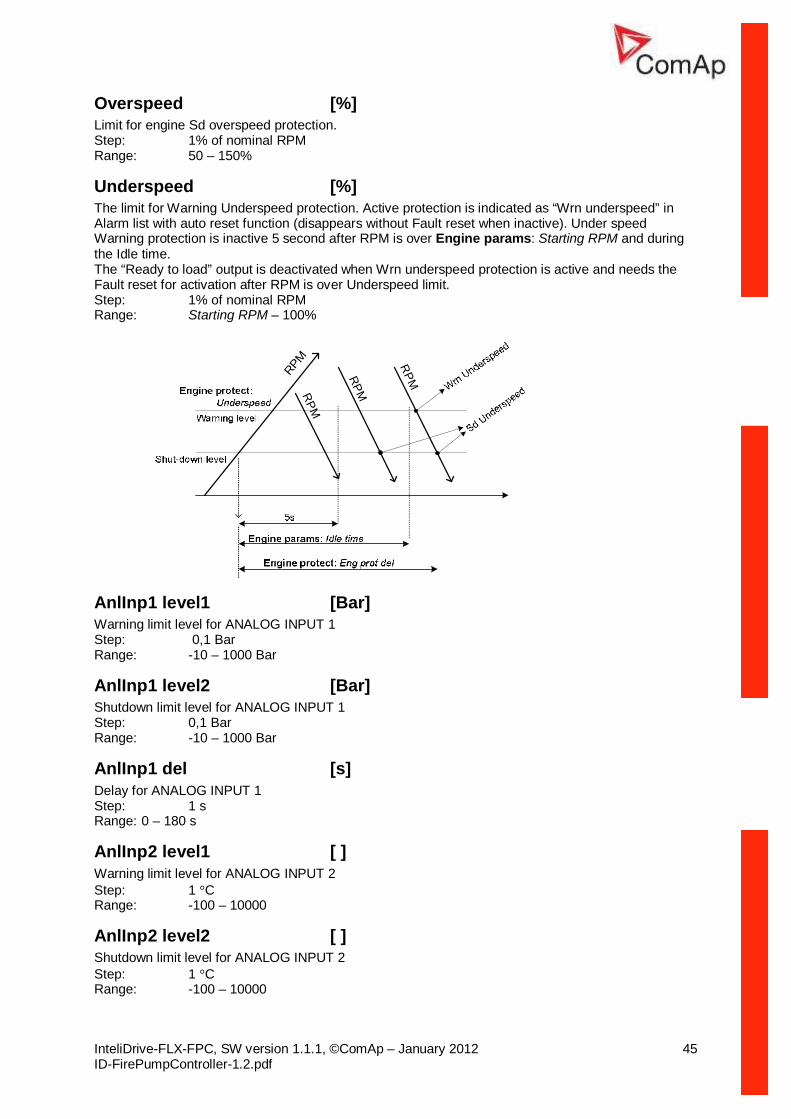
Overspeed [%] Limit for engine Sd overspeed protection. Step: 1% of nominal RPM Range: 50 – 150%
Underspeed [%] The limit for Warning Underspeed protection. Active protection is indicated as “Wrn underspeed” in Alarm list with auto reset function (disappears without Fault reset when inactive). Under speed Warning protection is inactive 5 second after RPM is over Engine params: Starting RPM and during the Idle time. The “Ready to load” output is deactivated when Wrn underspeed protection is active and needs the Fault reset for activation after RPM is over Underspeed limit. Step: 1% of nominal RPM Range: Starting RPM – 100%
RPM
RPM
RPM
RPM
AnlInp1 level1 [Bar] Warning limit level for ANALOG INPUT 1 Step: 0,1 Bar Range: -10 – 1000 Bar
AnlInp1 level2 [Bar] Shutdown limit level for ANALOG INPUT 1 Step: 0,1 Bar Range: -10 – 1000 Bar
AnlInp1 del [s] Delay for ANALOG INPUT 1 Step: 1 s Range: 0 – 180 s
AnlInp2 level1 [ ] Warning limit level for ANALOG INPUT 2 Step: 1 °C Range: -100 – 10000
AnlInp2 level2 [ ] Shutdown limit level for ANALOG INPUT 2 Step: 1 °C Range: -100 – 10000
Time stamp per [min] Time interval for periodic history records. Step: 1 min Range: 0 – 200min
#SummerTimeMod [ DISABLED / WINTER / SUMMER,WINTER-S, SUMMER-S ] DISABLED: Automatic switching between summer and wintertime is disabled. WINTER (SUMMER) : Automatic switching between summer and wintertime is enabled and it is set to winter (summer) season. WINTER-S (SUMMER-S) : Modification for southern hemisphere.
#Time [HHMMSS] Actual time.
#Date [DDMMYYYY] Actual date.
Timer 1,2 Function No Func: Corresponding Timer 1, 2 binary output activation only. Auto Run: Engine start in AUT mode.
Timer1..2 repeat [NONE/MONDAY/TUESDAY/WEDNESDAY/THURSDAY/WEDNESDAY/FRIDAY/SATURDAY/SUNDAY/MON-FRI/MON-SAT/MON-SUN/SAT-SUN] Defines TIMER1 activation. Binary output TIMER1 is internally linked with Rem Start/Stop binary input – i.e. can activate the periodic engine start in AUT mode. Refer to binary inputs for details. NONE: Timer function is disabled MONDAY, TUESDAY, WEDNESDAY, THURSDAY, WEDNESDAY, FRIDAY, SATURDAY, SUNDAY: Timer is activated on daily basis. MON-FRI, MON-SAT, SAT-SUN: Timer is activated on selected day interval.
Timer1..2 ON time Day time when Timer 1..2 output activates.
Timer1..2Duration Duration of Timer 1..2 output. Step: 1 min Range: 1 – 1440 s
Sensor spec
Calibr AI1, AI2, AI3 […] Calibrating constant to adjust the measured value of controller analog inputs. Physical dimension of calibrating constant is corresponding to Analog input. Step: 1 Range: -1000 – +1000 Hint: Calibration constants have to be adjusted when measured value is near the alarm level. User curves A, B, C can be defined by LiteEdit (3.0 or higher) software.
CalibrAInAIO 1..4 […] Calibrating constant to adjust the measured value of IL-NT-AIO analog inputs. Physical dimension of calibrating constant is corresponding to Analog input. Step: 1 Range: -1000 – +1000
IL-NT-AIO module
AnlInAIO1..4 lev1 [ ] The level for IL-NT-AIO ANALOG INPUT 1..4 alarm detection. Step: 1 Range: -100 - +10000
AnlInAIO1..4 lev2 [ ] The level for IL-NT-AIO ANALOG INPUT 1..4 alarm detection. Step: 1 Range: -100 - +10000
AnlInAIO1..4 del [s] Delay for IL-NT-AIO ANALOG INPUT 1..4 alarm. Step: 1 s Range: 0 - 180 s Hint: IL-NT-AIO analog inputs protection alarms can be configured following way Configuration Protection Under Protection is activated only when measured value is under measured level. Over Protection is activated only when measured value is over measured level. Under+fls Level 2 protection is activated by sensor fail as well. Over+fls Level 2 protection is activated by sensor fail as well.
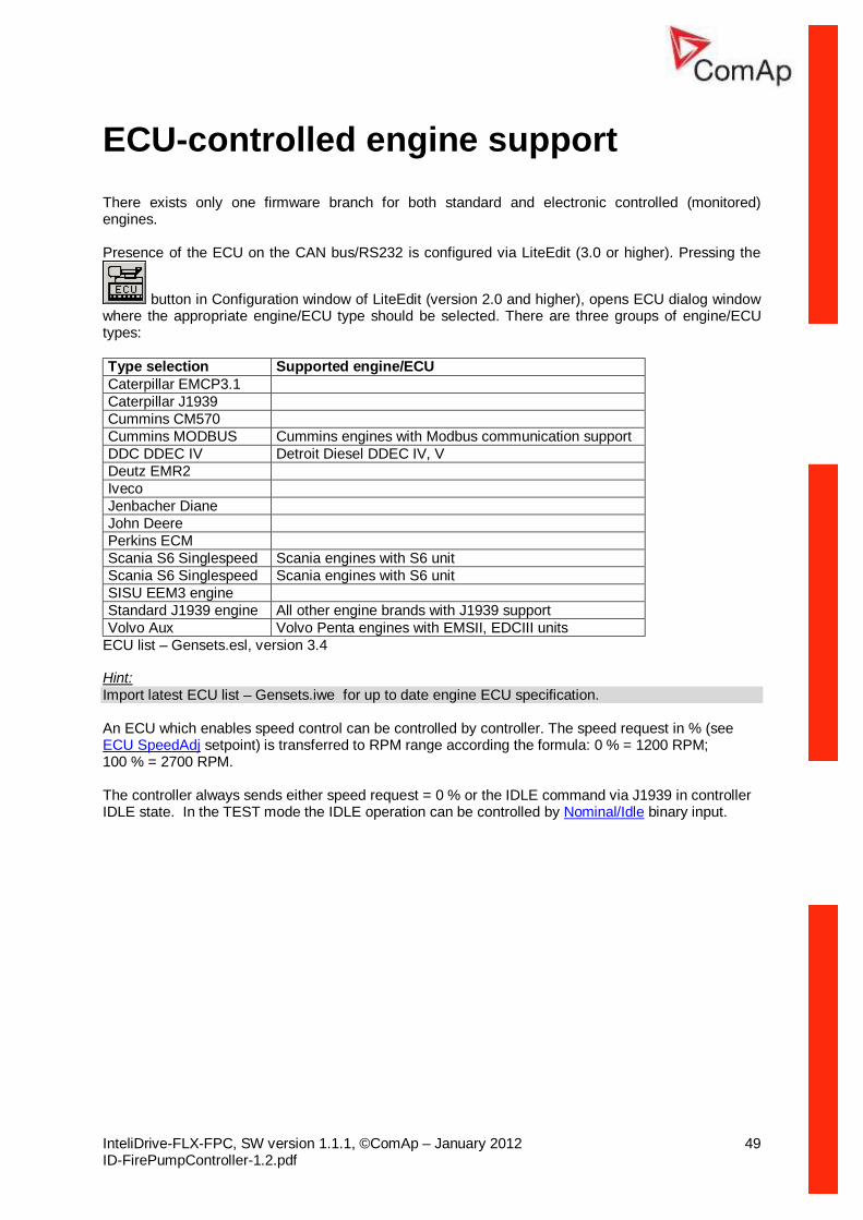
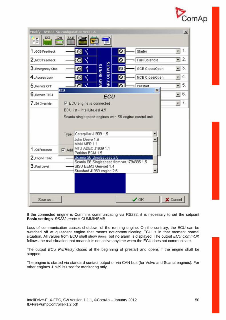
ECU-controlled engine support There exists only one firmware branch for both standard and electronic controlled (monitored) engines. Presence of the ECU on the CAN bus/RS232 is configured via LiteEdit (3.0 or higher). Pressing the
button in Configuration window of LiteEdit (version 2.0 and higher), opens ECU dialog window where the appropriate engine/ECU type should be selected. There are three groups of engine/ECU types: Type selection Supported engine/ECU Caterpillar EMCP3.1 Caterpillar J1939 Cummins CM570 Cummins MODBUS Cummins engines with Modbus communication support DDC DDEC IV Detroit Diesel DDEC IV, V Deutz EMR2 Iveco Jenbacher Diane John Deere Perkins ECM Scania S6 Singlespeed Scania engines with S6 unit Scania S6 Singlespeed Scania engines with S6 unit SISU EEM3 engine Standard J1939 engine All other engine brands with J1939 support Volvo Aux Volvo Penta engines with EMSII, EDCIII units
ECU list – Gensets.esl, version 3.4 Hint: Import latest ECU list – Gensets.iwe for up to date engine ECU specification. An ECU which enables speed control can be controlled by controller. The speed request in % (see ECU SpeedAdj setpoint) is transferred to RPM range according the formula: 0 % = 1200 RPM; 100 % = 2700 RPM. The controller always sends either speed request = 0 % or the IDLE command via J1939 in controller IDLE state. In the TEST mode the IDLE operation can be controlled by Nominal/Idle binary input.
If the connected engine is Cummins communicating via RS232, it is necessary to set the setpoint Basic settings: RS232 mode = CUMMINSMB. Loss of communication causes shutdown of the running engine. On the contrary, the ECU can be switched off at quiescent engine that means not-communicating ECU is in that moment normal situation. All values from ECU shall show ####, but no alarm is displayed. The output ECU CommOK follows the real situation that means it is not active anytime when the ECU does not communicate.
The output ECU PwrRelay closes at the beginning of prestart and opens if the engine shall be stopped.
The engine is started via standard contact output or via CAN bus (for Volvo and Scania engines). For other engines J1939 is used for monitoring only.
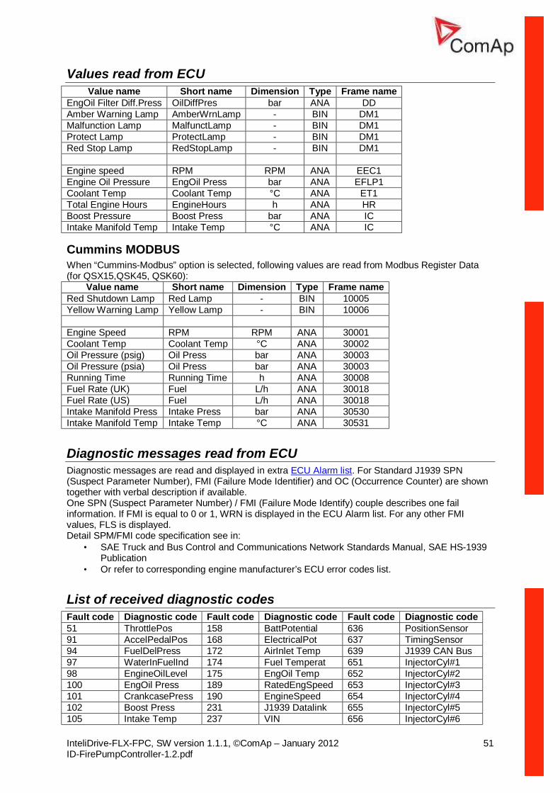
Values read from ECU Value name Short name Dimension Type Frame name
EngOil Filter Diff.Press OilDiffPres bar ANA DD Amber Warning Lamp AmberWrnLamp - BIN DM1 Malfunction Lamp MalfunctLamp - BIN DM1 Protect Lamp ProtectLamp - BIN DM1 Red Stop Lamp RedStopLamp - BIN DM1 Engine speed RPM RPM ANA EEC1 Engine Oil Pressure EngOil Press bar ANA EFLP1 Coolant Temp Coolant Temp °C ANA ET1 Total Engine Hours EngineHours h ANA HR Boost Pressure Boost Press bar ANA IC Intake Manifold Temp Intake Temp °C ANA IC
Cummins MODBUS When “Cummins-Modbus” option is selected, following values are read from Modbus Register Data (for QSX15,QSK45, QSK60):
Value name Short name Dimension Type Frame name Red Shutdown Lamp Red Lamp - BIN 10005 Yellow Warning Lamp Yellow Lamp - BIN 10006 Engine Speed RPM RPM ANA 30001 Coolant Temp Coolant Temp °C ANA 30002 Oil Pressure (psig) Oil Press bar ANA 30003 Oil Pressure (psia) Oil Press bar ANA 30003 Running Time Running Time h ANA 30008 Fuel Rate (UK) Fuel L/h ANA 30018 Fuel Rate (US) Fuel L/h ANA 30018 Intake Manifold Press Intake Press bar ANA 30530 Intake Manifold Temp Intake Temp °C ANA 30531
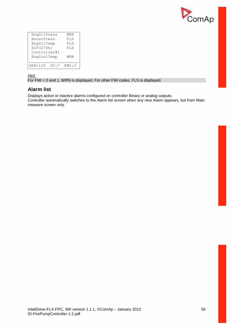
Diagnostic messages read from ECU Diagnostic messages are read and displayed in extra ECU Alarm list. For Standard J1939 SPN (Suspect Parameter Number), FMI (Failure Mode Identifier) and OC (Occurrence Counter) are shown together with verbal description if available. One SPN (Suspect Parameter Number) / FMI (Failure Mode Identify) couple describes one fail information. If FMI is equal to 0 or 1, WRN is displayed in the ECU Alarm list. For any other FMI values, FLS is displayed. Detail SPM/FMI code specification see in:
• SAE Truck and Bus Control and Communications Network Standards Manual, SAE HS-1939 Publication
• Or refer to corresponding engine manufacturer’s ECU error codes list.
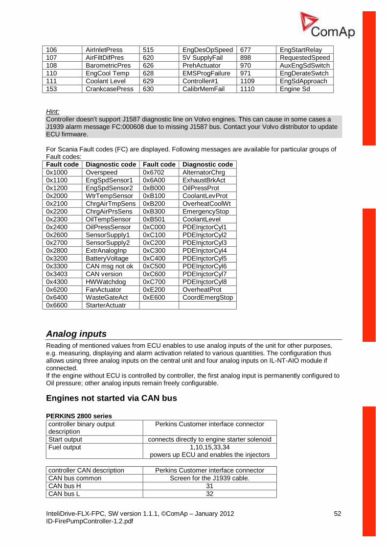
106 AirInletPress 515 EngDesOpSpeed 677 EngStartRelay 107 AirFiltDifPres 620 5V SupplyFail 898 RequestedSpeed 108 BarometricPres 626 PrehActuator 970 AuxEngSdSwitch 110 EngCool Temp 628 EMSProgFailure 971 EngDerateSwtch 111 Coolant Level 629 Controller#1 1109 EngSdApproach 153 CrankcasePress 630 CalibrMemFail 1110 Engine Sd Hint: Controller doesn’t support J1587 diagnostic line on Volvo engines. This can cause in some cases a J1939 alarm message FC:000608 due to missing J1587 bus. Contact your Volvo distributor to update ECU firmware. For Scania Fault codes (FC) are displayed. Following messages are available for particular groups of Fault codes: Fault code Diagnostic code Fault code Diagnostic code 0x1000 Overspeed 0x6702 AlternatorChrg 0x1100 EngSpdSensor1 0x6A00 ExhaustBrkAct 0x1200 EngSpdSensor2 0xB000 OilPressProt 0x2000 WtrTempSensor 0xB100 CoolantLevProt 0x2100 ChrgAirTmpSens 0xB200 OverheatCoolWt 0x2200 ChrgAirPrsSens 0xB300 EmergencyStop 0x2300 OilTempSensor 0xB501 CoolantLevel 0x2400 OilPressSensor 0xC000 PDEInjctorCyl1 0x2600 SensorSupply1 0xC100 PDEInjctorCyl2 0x2700 SensorSupply2 0xC200 PDEInjctorCyl3 0x2800 ExtrAnalogInp 0xC300 PDEInjctorCyl4 0x3200 BatteryVoltage 0xC400 PDEInjctorCyl5 0x3300 CAN msg not ok 0xC500 PDEInjctorCyl6 0x3403 CAN version 0xC600 PDEInjctorCyl7 0x4300 HWWatchdog 0xC700 PDEInjctorCyl8 0x6200 FanActuator 0xE200 OverheatProt 0x6400 WasteGateAct 0xE600 CoordEmergStop 0x6600 StarterActuatr
Analog inputs Reading of mentioned values from ECU enables to use analog inputs of the unit for other purposes, e.g. measuring, displaying and alarm activation related to various quantities. The configuration thus allows using three analog inputs on the central unit and four analog inputs on IL-NT-AIO module if connected. If the engine without ECU is controlled by controller, the first analog input is permanently configured to Oil pressure; other analog inputs remain freely configurable.
Engines not started via CAN bus PERKINS 2800 series controller binary output description
powers up ECU and enables the injectors controller CAN description Perkins Customer interface connector CAN bus common Screen for the J1939 cable. CAN bus H 31 CAN bus L 32
controller CAN description Cummins ISB 9 pin Deutsch connector CAN bus common SAE J1939 shield - screen for J1939 cable. CAN bus H SAE J1939 signal CAN bus L SAE J1939 return
Background of the sensor calibration To correct measuring error of each analog input (pressure, temperature, level) calibrating constants within 10 % of measure range should be set. Three (seven) calibrating constants are set in physical units - bar, oC, % . From these constants are counted equivalent calibrating resistances which are internally (in software) add to sensor resistance. At the moment of calibration (ENTER pressing) is calculated (and in memory saved) calibrating resistance (in Ω). This value is added to measured sensor resistance before calculation of the AI1 (AI2 or AI3) value. Example: controller display Temperature 70 °C and real value is 73 °C. After setting Calibr AI1 to +3 °C (and pressing ENTER) controller calculates corresponding resistance (e.g.5Ω) and saves this value into the memory. The resistance is then added to all calculations (e.g. instead of 70°C -> 73°C, or e.g. instead of 5°C -> 6°C). Hint: The calibration must be done at the operational point of the analog input (e.g. 80°C, 4.0Bar etc..)
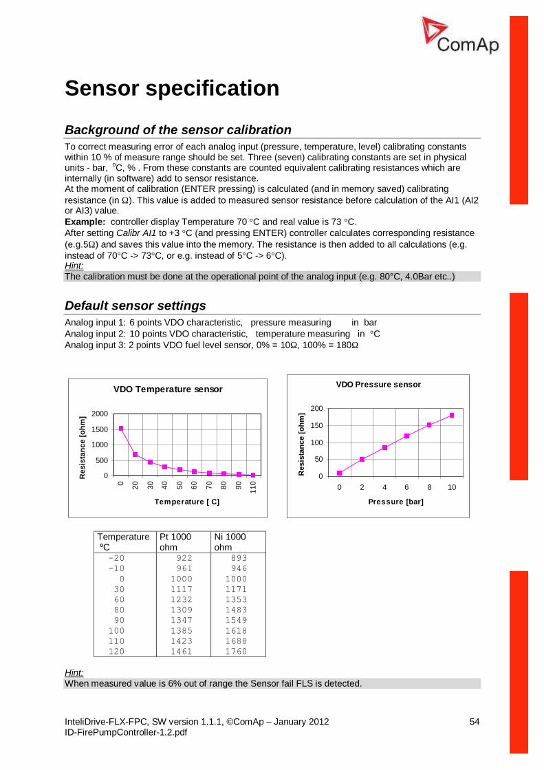
Default sensor settings Analog input 1: 6 points VDO characteristic, pressure measuring in bar Analog input 2: 10 points VDO characteristic, temperature measuring in °C Analog input 3: 2 points VDO fuel level sensor, 0% = 10Ω, 100% = 180Ω
VDO Temperature sensor
0
500
1000
1500
2000
0 20 30 40 50 60 70 80 90 110
Temperature [ C]
Res
ista
nce
[ohm
]
VDO Pressure sensor
0
50
100
150
200
0 2 4 6 8 10
Pressure [bar]
Res
ista
nce
[ohm
]
Temperature ºC
Pt 1000 ohm
Ni 1000 ohm
-20 -10 0 30 60 80 90 100 110 120
922 961 1000 1117 1232 1309 1347 1385 1423 1461
893 946 1000 1171 1353 1483 1549 1618 1688 1760
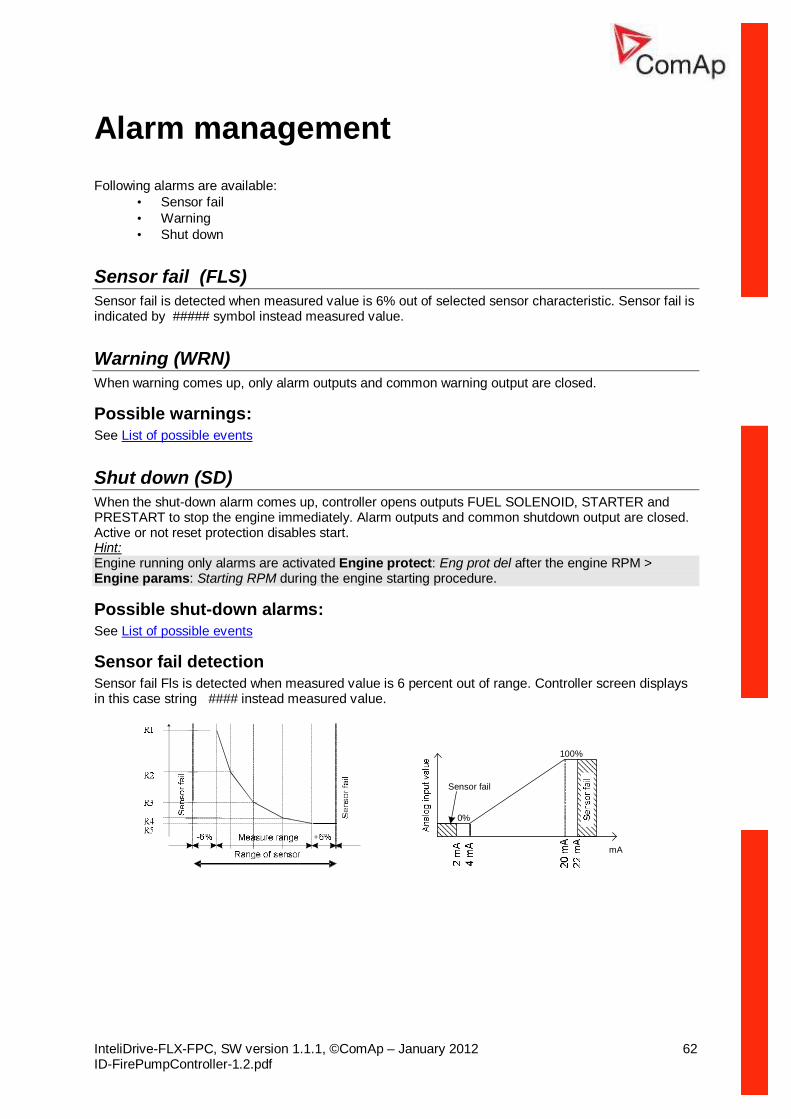
Hint: When measured value is 6% out of range the Sensor fail FLS is detected.
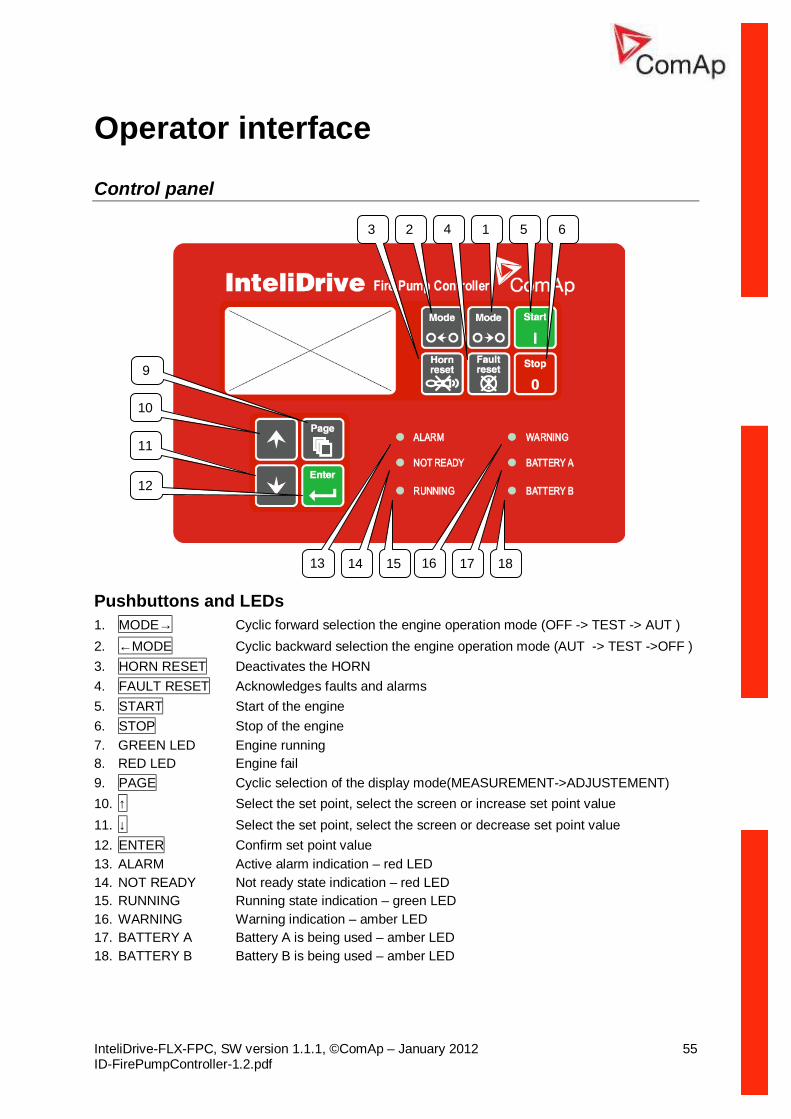
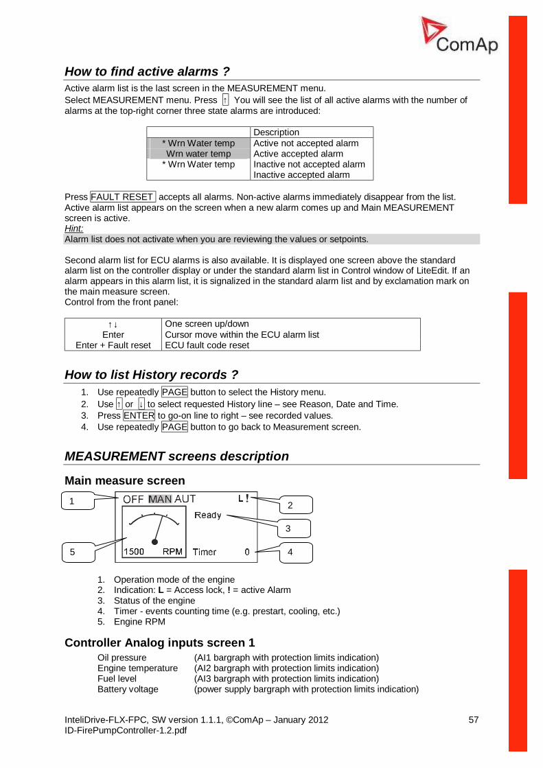
Pushbuttons and LEDs 1. MODE→ Cyclic forward selection the engine operation mode (OFF -> TEST -> AUT ) 2. ←MODE Cyclic backward selection the engine operation mode (AUT -> TEST ->OFF ) 3. HORN RESET Deactivates the HORN 4. FAULT RESET Acknowledges faults and alarms 5. START Start of the engine 6. STOP Stop of the engine 7. GREEN LED Engine running 8. RED LED Engine fail 9. PAGE Cyclic selection of the display mode(MEASUREMENT->ADJUSTEMENT) 10. ↑ Select the set point, select the screen or increase set point value 11. ↓ Select the set point, select the screen or decrease set point value 12. ENTER Confirm set point value 13. ALARM Active alarm indication – red LED 14. NOT READY Not ready state indication – red LED 15. RUNNING Running state indication – green LED 16. WARNING Warning indication – amber LED 17. BATTERY A Battery A is being used – amber LED 18. BATTERY B Battery B is being used – amber LED
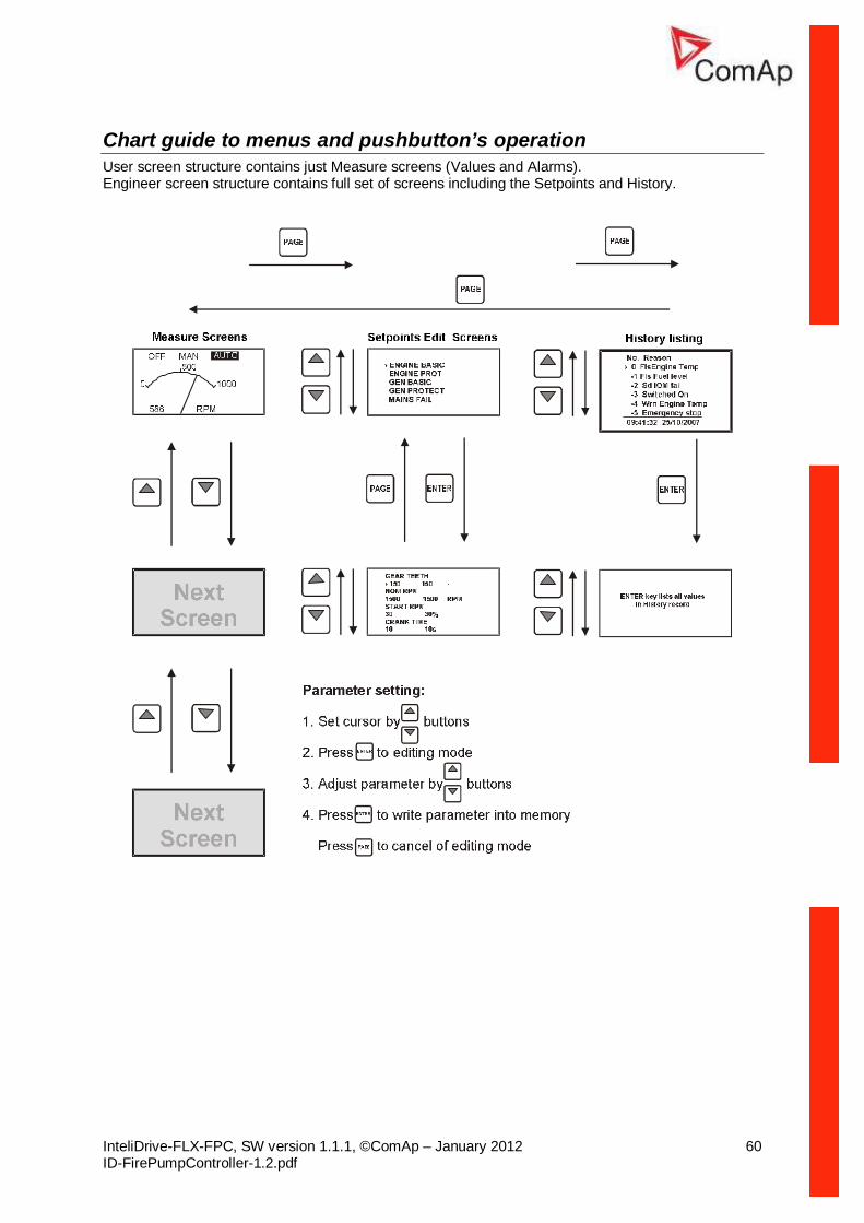
Display menus There are 3 display menus available: MEASUREMENT and ADJUSTMENT and HISTORY. Each menu consists of several screens. Press repeatedly PAGE button to select requested menu.
How to select the engine mode ? Use MODE→ or ←MODE to select requested engine operation mode (OFF – TEST – AUT)
How to view measured data? 1. Use repeatedly PAGE button to select the MEASUREMENT menu. 2. Use ↑ and ↓ to select the screen with requested data.
How to view and edit set points? 1. Use repeatedly PAGE button to select the ADJUSTMENT menu. 2. Use ↑ or ↓ to select requested set points group. 3. Press ENTER to confirm. 4. Use ↑ or ↓ to select requested set point. 5. Set points marked “*” are password protected. 6. Press ENTER to edit. 7. Use ↑ or ↓ to modify the set point. When ↑ or ↓ is pressed for 2 sec, auto repeat function is
activated. 8. Press ENTER to confirm or PAGE to leave without change. 9. Press PAGE to leave selected set points group.
How to change the display contrast? Press ENTER and ↑ or ↓ at the same time to adjust the best display contrast Hint: Only in MEASUREMENT menu.
How to check the serial number and software revision? Press ENTER and then PAGE. This activates the panel LED test. On the display you can see (for 10 seconds) controller INFO screen containing:
1) Controller name (see Basic setting group) 2) Controller serial number (8 character number) 3) SW version: the first is the firmware version number; the second is configuration table number. 4) Application: FPC 5) Branch: Standard
Hint: Only in MEASUREMENT menu.
How to change language? Hold ENTER and then press PAGE to get to Serial number and software revision screen. Then press PAGE to enter Language selection screen. Use ↑ or ↓ to select desired langue and press ENTER to confirm selection.
How to switch User interface? Hold ENTER and then press PAGE to get to Serial number and software revision screen. Then twice press PAGE to enter User interface. Use ↑ or ↓ to select User or Engineer structure of screens and press ENTER to confirm selection.
How to find active alarms ? Active alarm list is the last screen in the MEASUREMENT menu. Select MEASUREMENT menu. Press ↑ You will see the list of all active alarms with the number of alarms at the top-right corner three state alarms are introduced:
Description * Wrn Water temp Active not accepted alarm Wrn water temp Active accepted alarm
* Wrn Water temp Inactive not accepted alarm Inactive accepted alarm
Press FAULT RESET accepts all alarms. Non-active alarms immediately disappear from the list. Active alarm list appears on the screen when a new alarm comes up and Main MEASUREMENT screen is active. Hint: Alarm list does not activate when you are reviewing the values or setpoints. Second alarm list for ECU alarms is also available. It is displayed one screen above the standard alarm list on the controller display or under the standard alarm list in Control window of LiteEdit. If an alarm appears in this alarm list, it is signalized in the standard alarm list and by exclamation mark on the main measure screen. Control from the front panel:
↑↓ One screen up/down Enter Cursor move within the ECU alarm list
Enter + Fault reset ECU fault code reset
How to list History records ? 1. Use repeatedly PAGE button to select the History menu. 2. Use ↑ or ↓ to select requested History line – see Reason, Date and Time. 3. Press ENTER to go-on line to right – see recorded values. 4. Use repeatedly PAGE button to go back to Measurement screen.
MEASUREMENT screens description
Main measure screen
1. Operation mode of the engine 2. Indication: L = Access lock, ! = active Alarm 3. Status of the engine 4. Timer - events counting time (e.g. prestart, cooling, etc.) 5. Engine RPM
Controller Analog inputs screen 1 Oil pressure (AI1 bargraph with protection limits indication) Engine temperature (AI2 bargraph with protection limits indication) Fuel level (AI3 bargraph with protection limits indication) Battery voltage (power supply bargraph with protection limits indication)
Controller Analog inputs screen 2 Battery A voltage (Battery A voltage bargraph with protection limits indication) Battery B voltage (Battery B voltage bargraph with protection limits indication)
AnInIOM Analog inputs screen AnInIOM1 (AI1 bargraph with protection limits indication) AnInIOM2 (AI2 bargraph with protection limits indication) AnInIOM3 (AI3 bargraph with protection limits indication) AnInIOM3 (AI3 bargraph with protection limits indication)
Hint: This screen is shown/hidden depending on whether the IL-NT-AIO is configured or not.
Controller Binary inputs BI1 to BI7
Controller Binary outputs BO1 to BO7
ECU State ECU YellowLamp ECU RedLamp
WaitToStart Hint: This screen is shown/hidden depending on whether the ECU is configured or not.
ECU Values Oil pressure Bar or psi Water temp °C or °F PercLoadAtCS % (Percentual load at current speed) Boost pressure Bar or psi ManifoldTemp °C or °F
Fuel rate L/h or gph Hint: This screen is shown/hidden depending on whether the ECU is configured or not. Other screens are shown/hidden depending on whether the plug-in module is configured or not.
Statistic Run hours Number of starts E-Stop Number of engine Emergency stops (without Shut-downs) ShutDown Number of engine Shut down stops (without Emergency stops) NextServTime Hint: Running time is measured in complete minutes, displayed in complete hours. Values are stored in nonvolatile memory.
ECU AlarmList Diagnostic messages are read from ECU and displayed in this second alarm list. For Standard J1939 engines SPN (Suspect Parameter Number), FMI (Failure Mode Identifier) and OC (Occurrence Counter) are shown together with verbal description if available. Following image shows displaying of ECU alarms in the second alarm list. The additional information for the row selected by cursor is on the last row (SPN, OC and FMI codes). If the verbal description of alarm is not available, the SPN (decimal and hexadecimal) is displayed.
Hint: For FMI = 0 and 1, WRN is displayed. For other FMI codes, FLS is displayed.
Alarm list Displays active or inactive alarms configured on controller Binary or analog outputs. Controller automatically switches to the Alarm list screen when any new Alarm appears, but from Main measure screen only.
Chart guide to menus and pushbutton’s operation User screen structure contains just Measure screens (Values and Alarms). Engineer screen structure contains full set of screens including the Setpoints and History.
OFF mode No start of the engine is possible. Outputs STARTER and FUEL SOLENOID are not energized. No reaction if START,STOP buttons are pressed.
TEST mode Manual mode – engine is started and stopped by operator. START - starts the engine. STOP - stops the engine. The test start is energized from the battery A. When the start with the battery A was not successful, the controller tries to start with the battery B. But when the start with the battery A is successful, the test is over, because it is considered if the battery B voltage is OK and the start with battery A was successful, then there is conclusion that the engine would start even with the battery B. How to test the start with the battery B even if the start with battery A is successful: § After the successful start from the battery A, the engine is running. § Stop the engine manually (with the panel button Stop) § Wait until the yellow LED BATTERY B on the controller panel is blinking § If the panel button Start is pushed while LED Battery B is blinking, the controller will try to start
from the battery B. § If no start order comes while LED Battery B is blinking, the controller passes to the initial TEST
status and is ready again to start from the battery A. Hint: The engine can run without load unlimited time. The controller does not automatically stop the running engine in TEST mode. The controller does not start the engine when binary input REM START/STOP is closed.
AUT mode The controller does not respond to START, STOP buttons. Engine start/stop request is given by:
- binary input REM START/STOP (pressure contact), - when analog input Sprinkler pressure is below adjusted limit - when daily/weekly schedule auto start is enabled. - seeTimer1 setpoints - In AUT mode, the majority of alarms are disabled, i.e. the engine starts and run even if an
alarm is active. All alarms are disabled except the binary input EMERGENCY STOP and "engine overspeed protection".
Sensor fail (FLS) Sensor fail is detected when measured value is 6% out of selected sensor characteristic. Sensor fail is indicated by ##### symbol instead measured value.
Warning (WRN) When warning comes up, only alarm outputs and common warning output are closed.
Possible warnings: See List of possible events
Shut down (SD) When the shut-down alarm comes up, controller opens outputs FUEL SOLENOID, STARTER and PRESTART to stop the engine immediately. Alarm outputs and common shutdown output are closed. Active or not reset protection disables start. Hint: Engine running only alarms are activated Engine protect: Eng prot del after the engine RPM > Engine params: Starting RPM during the engine starting procedure.
Possible shut-down alarms: See List of possible events
Sensor fail detection Sensor fail Fls is detected when measured value is 6 percent out of range. Controller screen displays in this case string #### instead measured value.
Engine operation states Engine state machine Init Auto test during controller power on Not ready Engine is not ready to start Prestart Prestart sequence in process, Prestart output is closed Cranking Engine is cranking Pause Pause between start attempts Starting Starting speed is reached and the Idle timer is running Running Engine is running at nominal speed Stop Stop Shutdown Shut-down alarm activated Ready Engine is ready to run Cooling Engine is cooling before stop EmergMan Emergency Manual engine operation AFterCool Engine after cooling - Cooling Pump output is closed
List of possible alarms
Events specification Protection type
Information on binary output available (See list of Binary outputs)
Description
Wrn Oil Press WRN YES Oil pressure is smaller than Wrn Oil press setpoint.
Sd Oil Press SD NO Oil pressure is smaller than Sd Oil press setpoint.
Wrn Engine Temp WRN YES Water temperature is greater than Wrn Water temp setpoint.
Sd Engine Temp SD NO Water temperature is greater than Sd Water temp setpoint.
Wrn Fuel Level WRN YES Fuel level is smaller than Wrn Fuel Level setpoint.
Sd Fuel Level SD NO Fuel level is smaller than Sd Fuel Level setpoint.
Wrn AnInAIO WRN YES Warning alarm configurable on the input of IL-NT-AIO.
Sd AnInAIO SD YES Shutdown alarm configurable on the input of IL-NT-AIO.
Binary input Configurable YES Configurable Warning/Shutdown alarms on the inputs of controller.
SuppBatt V WRN YES Power Supply voltage is out of limits given by Batt A Over V and Batt A Under V Batt B Over V and Batt B Under V setpoints.
Battery A WRN YES Battery A voltage is out of limits given by Batt A over V and Batt A under V setpoints.
Battery B WRN YES Battery B voltage is out of limits given by Batt B over V and Batt B under V setpoints.
BatteryFlat SD YES If the controller switches off during starting sequence due to bad battery condition it doesn’t try to start again
Information on binary output available (See list of Binary outputs)
Description
and activates this protection. The controller displays the message after its restart. But when the Sprinkler binary input is active it overrides all SD alarms and the controller starts the engine automatically.
Start failed SD YES Engine start failed. ParamFail NONE NO Wrong checksum of parameters.
Happens typically after downloading new firmware or changing of the parameter. The controller stays in INIT mode. Check all parameters, write at least one new parameter.
Overspeed SD YES The protection comes active if the speed is greater than Overspeed setpoint.
Underspeed SD YES During starting of the engine when the RPM reached the value of Starting RPM setpoint the starter is switched off and the speed of the engine can drop under Start RPM again. Then the Underspeed protection becomes active. Protection evaluation starts 5 seconds after reaching StartingRPM.
EmergencyStop SD NO If the input Emergency stop is opened shutdown is immediately activated.
PickupFault SD NO Failure of magnetic pick-up sensor for speed measurement.
Stop fail SD YES Engine stop failed. WrnServiceTime WRN NO The period for servicing is set by the
NextServTime setpoint. The protection comes active if the running hours of the engine reach this value.
ChrgAlternFail WRN YES Failure of alternator for charging the battery.
SprinklActive WRN NO The protection is active if the output Sprinkler is closed.
Wrn RA15 fail WRN NO Warning alarm in case of lost connection to IGL-RA15 module.
Wrn ECU Alarm WRN NO ECU alarm list is not empty Low BackupBatt WRN NO RTC backup battery is flat
History file Controller stores a record of each important event into the history file. The history file seats 117 records. When the history file is full, the oldest records are removed. Hint: To force history download in LiteEdit (direct, modem or Internet) open History window and select History | Read history command.
Record structure Abbreviation Historical value Num Number of historical event Reason Event specification
Date Date of historical event in format DD/MM/YY Time Time of historical event in format HH:MM:SS RPM Engine speed BATA Battery A voltage BATB Battery B voltage UBat Battery voltage OilP Controller Analog input 1 value ( default Oil pressure) EngT Controller Analog input 2 value ( default Water temperature) FLvl Controller Analog input 3 value ( default Fuel level) AIM1 IL-NT-AIO Analog input 1 value (when configured) AIM2 IL-NT-AIO Analog input 2 value (when configured) AIM3 IL-NT-AIO Analog input 3 value (when configured) AIM4 IL-NT-AIO Analog input 4 value (when configured) BIN Controller Binary inputs BOUT Controller Binary inputs FC ECU alarm Failure Code FMI ECU alarm Failure Mode Identifier
Direct connection to the PC CONTROLLER can be connected directly with PC via optional IL-NT RS232 interface. Use the standard serial cable to connect PC with CONTROLLER. Hint: Make sure the grounding system on controller and PC – COM port (negative of the PC DC supply) are identical – before the first direct connection. There must not be any voltage between these two points otherwise the internal reversible fuse in controller burns out. The simple solution is to assure, that the PC supply 240/20V is ground free (GND terminal is not connected).
5 - GND
2 - RxD3 - TxD
PC
5 - GND
2 - RxD3 - TxD
RS2
32
RS2
32
230 VAC
0 VD
C
CONTROLLER
+-Battery
Required the samevoltage potentialbetween GND‘s
RS 232
PC software - LiteEdit (3.0 or higher) On the PC (for direct or modem connection) has to be installed the ComAp’s software package LiteEdit. (based on Windows 95 or newer platform) LiteEdit enables:
• read the quantities • adjust all set points • control the engine • configure the controller • select software configuration • modify alarm inputs and outputs • modify password, commands protections • direct, modem or Internet communication • language translator
Language translator Default archive contains English and Chinese languages. To change default Chinese (Unicode) to any Latin language use Remove and Add buttons in LiteEdit – Translator-Language window.
Modbus protocol The selection of the function of CONTROLLER serial port is done via the setpoint RS232 mode in Basic settings • 9600 bps, 8 data bits, 1 stop bit, no parity • Transfer mode RTU • Function 3 (Read Multiply Registers) • Function 6 (Write Single Register) • Function 16 (Write Multiply Registers)
• The response to an incoming message is sent with minimum 4.096 ms delay after message reception
The complete description of Modbus communication protocol can be found in Modbus Protocol Reference Guide PI-MBUS-300 and Open Modbus Specification Release 1.0. Both documents are available from web site at http://www.modicon.com/openmbus/ . Communication object vs. Register All the data intended for communication has its representation as communication objects in the controller. The communication object is represented by the n-byte array in the controller memory and identified by the unique 16-bit communication object number. The register, according to Modbus communication protocol, represents a two-byte data and in communication functions is referenced by 16-bit register address. Further in the description of communication functions the communication object number will always be used as a register address and length of the communication object will be expressed by number of registers. Just one communication object can be read or written by one communication function. Hint: To obtain communication object numbers it is possible to download the actual controller description on-line from controller or from (ail) archive and use “export data” function from LiteEdit software. Communication object list (exported from default CONTROLLER archive)
Remote communication Note: Refer to InteliCommunication guide for all additional information.
Internet connection CONTROLLER controllers can be monitored from LiteEdit 3.0 over the Internet using Internet Bridge (IG-IB) connected to the controller RS232 port. See demo example in explorer at address http://195.122.193.152/. For more details refer IB-Lite-1.2-Reference Guide.pdf.
GSM Modem setup Prior to start work with GSM modem run following program for GSM proper setup. Program writes all the necessary AT commands to configure the GSM modem properly for use with CONTROLLER. This program runs independent on LiteEdit:
• Start MS Windows-Start-Program files - LiteEdit –Gm_setup.exe. • Select COM port • Select iG-CU (=IS-CU) or iG-MU unit • Press Setup button • Follow commands in GSM Modem Setup window
Typical real baud rate for GSM data communication is 80 to 90 Bps. Hint: It is strongly recommended to use the same type of modem on the both sides (CONTROLLER and PC) of connection.
Mobile SIM card setting • Adjust SIM card in GSM modem following way: • enable data connection (when required) • no PIN code
Power supply Voltage supply 8-36V DC Consumption 40-430mA depend on supply voltage and temperature Consumption depends on supply voltage 0,104A at 8VDC 0,080A at 12VDC 0,051A at 24VDC 0,044A at 30VDC
0,040A at 36VDC Allowed supply voltage drop-out: 100ms from min. 10V return to min. 8V Battery voltage measurement tolerance 2 % at 24V Hint: For the supply voltage less than 7V the backlight of the display is switched off. Short-term voltage drops (e.g. during the engine cranking) do not affect the operation at all.
Operating conditions Operating temperature -20..+70oC Operating temperature (LowTemp version) -40..+70oC Storage temperature -30..+80oC Protection front panel IP65 Humidity 95% without condensation Standard conformity Low Voltage Directive EN 61010-1:95 +A1:97 Electromagnetic Compatibility EN 50081-1:94, EN 50081-2:96 EN 50082-1:99, EN 50082-2:97 Vibration 5 - 25 Hz, ±1,6mm
25 - 100 Hz, a = 4 g Shocks a = 200 m/s2
Low Temperature modification LCD display limits controller operating temperature range to –20 oC - + 70 oC even if the other electronic components work in wider temperature range. Internal preheating foil is mounted in InteliDrive-FLX LT to extend display operational temperature range. Preheating starts at temperature below 5 oC and preheating power depends on temperature and power supply voltage.
Technical data Standard Order code:
ID-yyy-xxxxx LT Operating temperature -20 oC..+70oC -40 oC..+70oC Storage temperature -30 oC..+80oC -30 oC..+80oC
Preheating foil increases controller current consumption
Preheating at ambient temperature Controller consumption at
No preheating 0 oC -20 oC -40 oC
12VDC 80 mA +75 mA +210 mA +325 mA 24VDC 51 mA +31 mA +100 mA +175 mA
InteliDrive-FLX LT works immediately after switch on at -30 oC and display becomes visible after a few minutes.
Dimensions and weight Dimensions 180x120x55mm Weight 450g
Binary inputs and outputs Binary inputs Number of inputs 7 Input resistance 4,2 kΩ Input range 0-36 VDC Switching voltage level for close contact indication 0-2 V Max voltage level for open contact indication 8-36 V
Binary open collector outputs Number of outputs 7 Maximum current 0,5 A Maximum switching voltage 36 VDC
Analog inputs AI1 – AI3 Not electrically separated Number of inputs 3 Resolution 10 bits Maximal resistance range 2500 Ω Input impedance 180 Ω for mA measuring Input impedance > 100 kΩ for V measuring Resistance measurement tolerance ± 2 % ± 2 Ω
Analog inputs Battery A and Battery B Not electrically separated Number of inputs 2 Resolution 10 bits Maximal voltage range 0,0 to 40,0 V Input impedance > 100 kΩ for V measuring Voltage measurement tolerance ± 2 % ± 20mV out of measured value
Analog inputs AI6 – AI9 Not electrically separated Number of inputs 4 Resolution 10 bits Maximal voltage range 0,000 to 10,000 V Input impedance > 50 kΩ for V measuring Voltage measurement tolerance ± 1,5 % ± 10mV out of measured value
Speed pick-up input Type of sensor magnetic pick-up (connection by shielded cable is
recommended) Minimum input voltage 2 Vpk-pk (from 4 Hz to 4 kHz) Maximum input voltage 50 Veff Minimum measured frequency 4 Hz Maximum measured frequency 10 kHz (min. input voltage 6Vpk-pk)
D+ function Max. D+ output current 300 mA Guaranteed level for signal Charging OK 80% of supply voltage
CAN bus interface Galvanically separated Maximal CAN bus length 200m Speed 250kBd Nominal impedance 120Ω Cable type twisted pair (shielded) Following dynamic cable parameters are important especially for maximal 200 meters CAN bus length and 32 iS-COM units connected: Nominal Velocity of Propagation min. 75% (max. 4,4 ns/m) Wire crosscut min.0,25 mm2 Maximal attenuation (at 1 MHz) 2 dB / 100m Recommended Industrial Automation & Process Control Cables: BELDEN (see http://www.belden.com):
• 3082A DeviceBus for Allen-Bradley DeviceNet • 3083A DeviceBus for Allen-Bradley DeviceNet • 3086A DeviceBus for Honeywell SDS • 3087A DeviceBus for Honeywell SDS • 3084A DeviceBus for Allen-Bradley DeviceNet • 3085A DeviceBus for Allen-Bradley DeviceNet • 3105A Paired EIA Industrial RS485 cable
LAPP CABLE (see http://www.lappcable.com)
• Unitronic BUS DeviceNet Trunk Cable • Unitronic BUS DeviceNet Drop Cable • Unitronic BUS CAN • Unitronic-FD BUS P CAN UL/CSA
IL-NT RS232 interface (optional card) Plugs into controller COMMUNICATIN MODULE port. Maximal distance 10m Speed 19.2kBd (STD) 9.6kBd (MODBUS) Recommend external converter: ADVANTECH – ADAM 4520: RS232 to RS422/485 converter, DIN rail, automatic RS485 bus supervision, no external data flow control signals, galvanic isolated. Recommended internal converter: ADVANTECH – PCL-745B or PCL745S : Dual port RS422/485 Interface card, automatic RS485 bus supervision, no external data flow control signals, galvanic isolated
IL-NT AOUT8 interface Plug-in into ID-Lite controller EXTENSION MODULE port. Number of PWM outputs 8 PWM frequency 5000Hz
Maximum current 0.5 A Maximum switching voltage 36 VDC Output resistance 1Ω Resolution 10 bits
IL-NT-AIO Plug-in into ID-Lite controller EXTENSION MODULE port. Number of Analog inputs: 4 (2400 Ohm, 20mA, 4V) Number of Analog outputs: 1 (21,16mA (max. load 100 Ohm), 4,69V (10mA), PWM 500Hz (5V/10mA)) Resolution: 10 bits Inputs: Maximal resistance range: 2400 Ohm Maximal voltage range: 4 V Current range: 0-20 mA Input impedance (current): 180 Ohm for mA measuring Input impedance (voltage): >68 kOhm for V measuring Resistance measurement tolerance: ± 2% +- 2 Ohm Voltage measurement tolerance: ± 1% +- 1mV Current measurement tolerance: ±2% +- 0,2mA Outputs: Voltage measurement tolerance: ± 1,5% +- 10mV Current measurement tolerance: ± 2% +- 0,1mA
IL-NT-BIO8 Plug-in into ID-Lite controller EXTENSION MODULE port. Number of Binary Inputs/Outputs: 8 (configurable as Input or Output) Max. one Binary output current: 0,4A Max total current per module: 2,5A
IL-NT-IO1 Plug-in into ID-Lite controller EXTENSION MODULE port. Number of Analog outputs: 4 Analog output range: 0 to +VBatt ±1V Number of binary inputs: 4 (equal to ID-Lite CU)
IGL-RA15
Power supply Voltage supply 8-36V DC Consumption 0,35-0,1A (+1A max horn output)
Depends on supply voltage
Operating conditions Operating temperature -20..+70oC Storage temperature -40..+80oC Protection front panel IP65
Dimensions and weight Dimensions 180x120x55mm Weight 950g