24
86431 POWER UNIT 342-86400-431PS Issue 2.1 March 2013 Technical Practice and Installation Manual Copyright © GE Multilin Inc. 2001-2013 JungleMUX SONET Multiplexer T1 Multiplexer (T1MX)
86431 POWER UNIT
334422--8866440000--443311PPSS
IIssssuuee 22..11
MMaarrcchh 22001133
Technical Practice
and
Installation Manual
Copyright © GE Multilin Inc. 2001-2013
JungleMUX SONET Multiplexer T1 Multiplexer (T1MX)
342-86400-431PS Issue 2.1 March 2013 Page 2
Copyright GE Multilin Inc. 2001-2013
JungleMUX SONET Multiplexer T1 Multiplexer (T1MX)
Power Unit Technical Practice and Installation Manual Copyright GE Multilin Inc. 2001-2013, All Rights Reserved The copyright of this document is the property of GE Multilin Inc. This document must not be copied, reprinted or reproduced in any material form, either wholly or in part, without the written consent of GE Multilin Inc. GE Multilin Inc. reserves the right to make changes and modifications to any part of this document without notice. GE Multilin Inc. is not responsible for any damages or losses incurred as a result of out-of-date or incorrect information contained in this document.
342-86400-431PS Issue 2.1 March 2013 Page 3
Copyright GE Multilin Inc. 2001-2013
TABLE OF CONTENTS
SECTION PAGE
1. INTRODUCTION ................................................ 5
Related Publication and Documentation Support .............................5
Product Color and Nomenclature .......................................................5
Handling and Packing ..........................................................................6
Revision History ...................................................................................6
2. UNIT OVERVIEW ............................................... 7
3. FRONT PANEL LAYOUT ................................... 8
(B)86431-0X Power Unit .......................................................................8 Extractor ............................................................................................ 8
B86431-4X Power Unit .........................................................................9 Extractor ............................................................................................ 9
4. UNIT DESCRIPTION ......................................... 10
(B)86431-0X Power Unit ......................................................................10
B86431-4X Power Unit ........................................................................10
5. INSTALLATION ................................................. 14
Pre-installation ....................................................................................14
Shelf Position ......................................................................................14
Power Requirements ..........................................................................15
Inserting the Unit in the Shelf ............................................................16
Removing the Unit from the Shelf .....................................................16
Paddleboard Connections ..................................................................17 Paddleboard Installation ................................................................. 18
342-86400-431PS Issue 2.1 March 2013 Page 4
Copyright GE Multilin Inc. 2001-2013
SECTION PAGE
6. MAINTENANCE and TROUBLESHOOTING .... 19
Troubleshooting ..................................................................................19
7. SPECIFICATIONS ............................................. 20
8. ORDERING INFORMATION ............................. 22
Equipment and Option Code List ......................................................22
APPENDIX A .......................................................... 23
List of Figures .....................................................................................23
List of Tables .......................................................................................23
APPENDIX B .......................................................... 24
List of Acronyms .................................................................................24

342-86400-431PS Issue 2.1 March 2013 Page 5
Copyright GE Multilin Inc. 2001-2013
1. INTRODUCTION
The 86431 Power Unit is one of the family of units in the GE Multilin’s JungleMUX SONET and T1 Multiplexer (T1MX) digital transport/access systems designed specifically for the requirements of the utility (Power, Transportation, Pipelines, Oil & Gas, etc.) industry using optical fiber transmission.
This manual explains how to operate, install and maintain the Power Unit.
There are two generations of Power Units for JungleMUX multiplexers; the old-generation (B)86431-0X units and new-generation B86431-4X units. The two units implement completely different hardware solutions. The descriptions and block diagrams for both generations of units are included.
Engineering documentation includes EAS schematics for all unit circuitry. Related Publication and Documentation Support
Additional information is provided in the JungleMUX Technical Overview and Reference Manual for system planning and engineering. The user may also find useful information in Technical Practice and Installation Manuals (TPIMs) for other JungleMUX units.
Customer inquiries for information contained in this manual should be directed to JungleMUX Product Line Management. GE Multilin appreciates notification of any possible errors or omissions contained herein.
Shipped with all purchased JungleMUX SONET and T1MX nodes is a Node Assignment Drawing (NAD), which provides necessary configuration details for the units and shelf location. Product Color and Nomenclature
The JungleMUX product line has undergone a transition to a new colored package. To distinguish between legacy gray and new black, a "B" prefix is added to all black shelf and unit code numbers to identify the item color. Note that there is no functional difference between gray and black versions of individual module types sharing the same code numbers as there is no difference in their internal electronics/hardware. Note that the gray colored modules were discontinued in June 2008. The modules added to the product portfolio after November 2007 have been available in black only.
342-86400-431PS Issue 2.1 March 2013 Page 6
Copyright GE Multilin Inc. 2001-2013
Handling and Packing Equipment with Electrostatic Discharge Sensitive (ESDS) devices or components must be shipped in protective containers and necessary handling precautions observed; otherwise, all warranties, expressed or implied, will be considered null and void. The following Electronic Industries Association (EIA) attention label appears on all GE Multilin EAS schematics and should be attached on all containers used for ESDS items to alert personnel that the contents requires special handling.
Revision History
Issue No. Issue Date Details of Change
Issue 1 Mar 1994 Document originated.
Issue 2 Nov 2011 Added B86431-4X units. General update.
Issue 2.1 Mar 2013 Minor error corrected.
HANDLE & ASSEMBLE
THIS UNIT CONTAINS STATIC SENSITIVE DEVICES
PER 562-48043-01
SENSITIVE
ELECTROSTATIC
OBSERVE PRECAUTIONS
FOR HANDLING
ATTENTION
DEVICES
342-86400-431PS Issue 2.1 March 2013 Page 7
Copyright GE Multilin Inc. 2001-2013
2. UNIT OVERVIEW
The 86431 Power Unit provides the interface between the customer-supplied station battery and a JungleMUX node. The unit’s input voltage requirement can be 24, 48 or 130 VDC depending on the unit option (refer to Section 8: Ordering Information for more information). The unit provides power supply to the shelf’s 5 VDC power bus. Normally, two Power Units are paralleled on the same shelf to provide redundancy in the case of a single Power Unit failure. If necessary, an additional (third) Power Unit can be installed in the shelf. The power buses of multiple shelves belonging to the same JungleMUX node can be paralleled (refer to the 86430 Equipment Shelf TPIM). It is strongly recommended that no more than six Power Units be paralleled. The old-generation (B)86431-0X Power Units can sustain a maximum load of 18 W while the new-generation B86431-4X Power Units can sustain a maximum load of 30 W on permanent basis. The (B)86431-0X and B86431-4X units are compatible and can be paralleled along the same power bus.
342-86400-431PS Issue 2.1 March 2013 Page 8
Copyright GE Multilin Inc. 2001-2013
3. FRONT PANEL LAYOUT
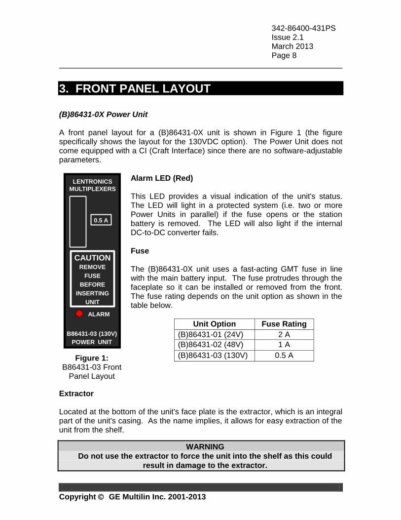
(B)86431-0X Power Unit A front panel layout for a (B)86431-0X unit is shown in Figure 1 (the figure specifically shows the layout for the 130VDC option). The Power Unit does not come equipped with a CI (Craft Interface) since there are no software-adjustable parameters.
Alarm LED (Red) This LED provides a visual indication of the unit's status. The LED will light in a protected system (i.e. two or more Power Units in parallel) if the fuse opens or the station battery is removed. The LED will also light if the internal DC-to-DC converter fails.
Fuse The (B)86431-0X unit uses a fast-acting GMT fuse in line with the main battery input. The fuse protrudes through the faceplate so it can be installed or removed from the front. The fuse rating depends on the unit option as shown in the table below.
Unit Option Fuse Rating
(B)86431-01 (24V) 2 A
(B)86431-02 (48V) 1 A
(B)86431-03 (130V) 0.5 A
Extractor Located at the bottom of the unit's face plate is the extractor, which is an integral part of the unit's casing. As the name implies, it allows for easy extraction of the unit from the shelf.
WARNING
Do not use the extractor to force the unit into the shelf as this could
result in damage to the extractor.
B86431-03 (130V)
BEFORE
POWER UNIT
ALARM
INSERTING
UNIT
REMOVE
FUSE
CAUTION
0.5 A
LENTRONICS
MULTIPLEXERS
Figure 1: B86431-03 Front
Panel Layout
342-86400-431PS Issue 2.1 March 2013 Page 9
Copyright GE Multilin Inc. 2001-2013
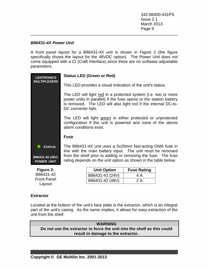
B86431-4X Power Unit A front panel layout for a B86431-4X unit is shown in Figure 2 (the figure specifically shows the layout for the 48VDC option). The Power Unit does not come equipped with a CI (Craft Interface) since there are no software adjustable parameters.
Status LED (Green or Red) This LED provides a visual indication of the unit's status. The LED will light red in a protected system (i.e. two or more power units in parallel) if the fuse opens or the station battery is removed. The LED will also light red if the internal DC-to-DC converter fails. The LED will light green in either protected or unprotected configuration if the unit is powered and none of the above alarm conditions exist.
Fuse The B86431-4X unit uses a 5x20mm fast-acting GMA fuse in line with the main battery input. The unit must be removed from the shelf prior to adding or removing the fuse. The fuse rating depends on the unit option as shown in the table below.
Unit Option Fuse Rating
B86431-41 (24V) 4 A
B86431-42 (48V) 2 A
Extractor Located at the bottom of the unit's face plate is the extractor, which is an integral part of the unit's casing. As the name implies, it allows for easy extraction of the unit from the shelf.
WARNING
Do not use the extractor to force the unit into the shelf as this could
result in damage to the extractor.
B86431-42 (48V)
POWER UNIT
STATUS
LENTRONICS
MULTIPLEXERS
Figure 2: B86431-42 Front Panel
Layout
342-86400-431PS Issue 2.1 March 2013 Page 10
Copyright GE Multilin Inc. 2001-2013
4. UNIT DESCRIPTION
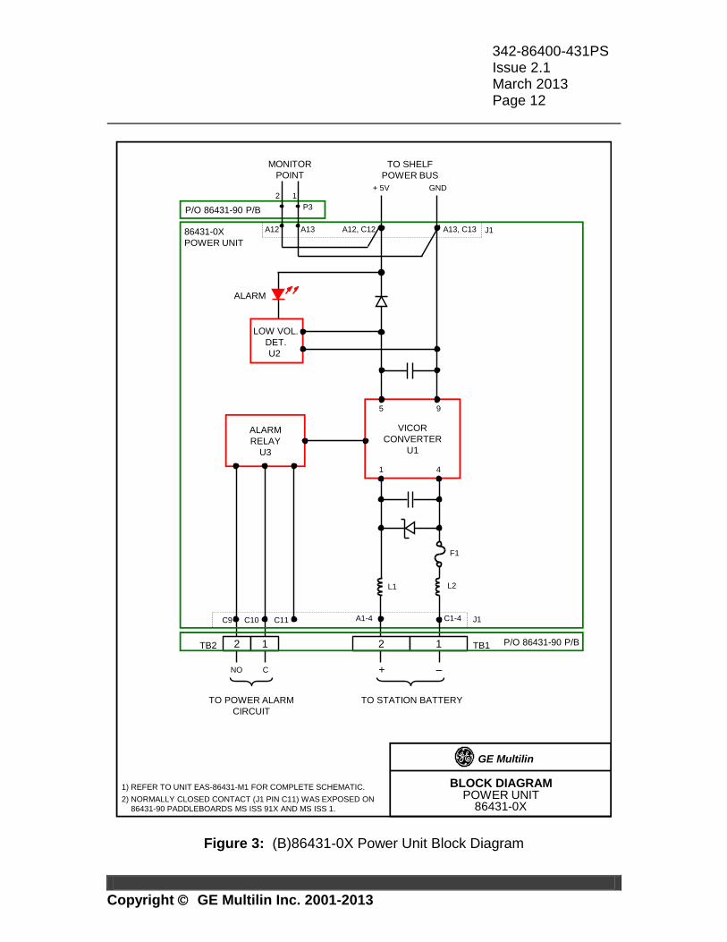
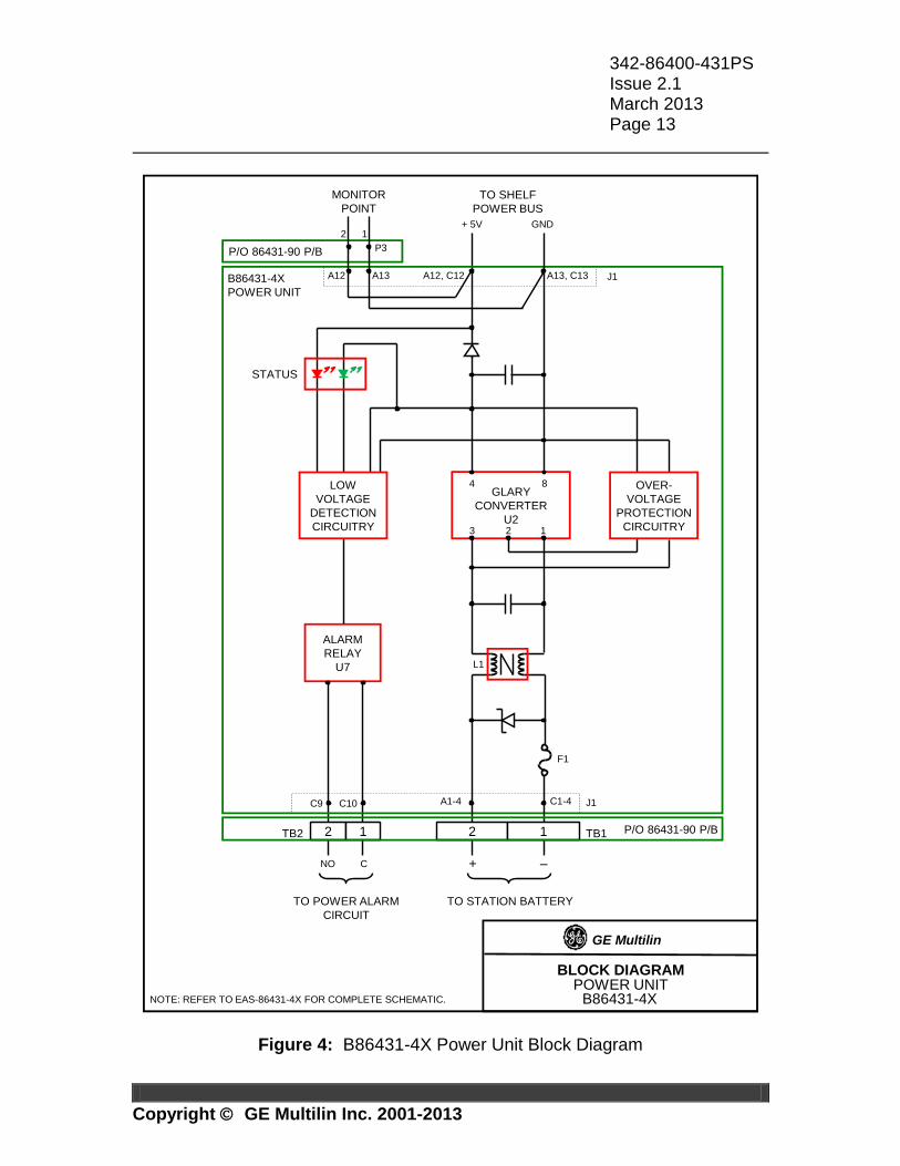
The 86431 Power Unit provides the regulated +5 V required for the JungleMUX shelf by converting station battery input to +5 VDC. The unit can interface various station battery inputs depending on the unit option. All customer connections for station battery input and alarm reporting are made on the interconnect paddleboard. Block diagrams for the (B)86431-0X and B86431-4X units are provided for reference purposes in Figure 3 and Figure 4, respectively. The user should refer to EAS-86431-M1 and EAS-86431-4X for complete circuit schematics. (B)86431-0X Power Unit Station battery is applied to TB1 of the paddleboard and fed to the unit via backplane connector J1. After being filtered from RF by L1, L2, C1, C2 and C3, the input DC power is sent to the DC-DC converter U1 (Vicor). The converter is an isolated DC-DC switching converter to allow operation from a floating station battery input. +5.35 VDC (measured at low loads) is applied to the shelf on J1(A12, C12) and shelf ground on J1(A13, C13). The low voltage detector U2 lights the Alarm LED which is powered from the shelf power bus if a second power unit is installed on the bus. Alarm relay U3 will provide a Form-C contact upon failure of U1 or absence of station battery. The NO contact is open when the alarm relay is energized and the unit is operating normally.1 B86431-4X Power Unit Station battery is applied to TB1 of the paddleboard and fed to the unit via backplane connector J1. After being filtered from RF by L1, C1, C2, C3, C4 and C21, the input DC power is sent to the DC-DC converter U2 (Glary). The converter is an isolated DC-DC switching converter to allow operation from a floating station battery input. +5.25 VDC (measured at output power of 15 W) is applied to the shelf on J1(A12, C12) and shelf ground on J1(A13, C13).
1 The NO contact is available on all versions of the 86431-90 Power Unit paddleboard. The NC contact was available on 86431-90 paddleboard versions MS ISS 91X and MS ISS 1.
342-86400-431PS Issue 2.1 March 2013 Page 11
Copyright GE Multilin Inc. 2001-2013
The low voltage detection circuitry turns the Red LED on (and Green LED off). The Red LED is powered from the shelf power bus if a second power unit is installed on the bus. Under normal conditions, the Green LED is on and Red LED is off. The low voltage detection circuitry also drives the Form-A alarm relay U7 and sets the contact into alarm state (contact closed) upon failure of U2 or absence of station battery. The contact is open when the alarm relay is energized and the unit is operating normally. The overvoltage protection circuitry is a backup for the primary overvoltage protection built in the converter module U2 itself and it is set to trigger a few tenths of a volt higher than the primary feedback system. It would activate only in the unlikely event of the primary feedback failure thus preventing uncontrollable rise of the output voltage. If an overvoltage condition is detected by the secondary feedback circuitry, the converter module’s PC input (U2(2)) is driven low which forces the converter into permanent shutdown state. This condition causes the undervoltage detection circuitry to light the Red LED and turn the Form-A contact into alarm state. The converter module can then be reset only by power cycling the unit; however, the unit must remain unplugged from the shelf for at least 2 seconds.
342-86400-431PS Issue 2.1 March 2013 Page 12
Copyright GE Multilin Inc. 2001-2013
BLOCK DIAGRAMPOWER UNIT
86431-0X
86431-0X
POWER UNIT
VICOR
CONVERTER
U1
5 9
1 4
J1A12, C12 A13, C13
F1
L2L1
A1-4 C1-4C9 C10 C11 J1
GE Multilin
LOW VOL.
DET.
U2
TO SHELF
POWER BUS
+ 5V GND
TO STATION BATTERY
+ –
P/O 86431-90 P/B
NO C
TO POWER ALARM
CIRCUIT
TB2 2 1 TB12 1
P/O 86431-90 P/B
MONITOR
POINT
P3
2 1
ALARM
RELAY
U3
A13A12
ALARM
1) REFER TO UNIT EAS-86431-M1 FOR COMPLETE SCHEMATIC.
2) NORMALLY CLOSED CONTACT (J1 PIN C11) WAS EXPOSED ON
86431-90 PADDLEBOARDS MS ISS 91X AND MS ISS 1.
Figure 3: (B)86431-0X Power Unit Block Diagram
342-86400-431PS Issue 2.1 March 2013 Page 13
Copyright GE Multilin Inc. 2001-2013
BLOCK DIAGRAMPOWER UNIT
B86431-4X
B86431-4X
POWER UNIT
NOTE: REFER TO EAS-86431-4X FOR COMPLETE SCHEMATIC.
GLARY
CONVERTER
U2
4 8
3 1
ALARM
RELAY
U7
J1A12, C12
TO SHELF
POWER BUS
+ 5V GND
L1
A1-4 C1-4C9 C10
+ –
P/O 86431-90 P/B
J1
GE Multilin
NO C
2
A13, C13
TB2 2 1 TB12 1
P/O 86431-90 P/B
MONITOR
POINT
P3
2 1
A13A12
F1
LOW
VOLTAGE
DETECTION
CIRCUITRY
OVER-
VOLTAGE
PROTECTION
CIRCUITRY
TO STATION BATTERYTO POWER ALARM
CIRCUIT
STATUS
Figure 4: B86431-4X Power Unit Block Diagram

342-86400-431PS Issue 2.1 March 2013 Page 14
Copyright GE Multilin Inc. 2001-2013
5. INSTALLATION
This section provides information for installing an 86431 Power Unit. All JungleMUX nodes are shipped with Power Units installed as per the Node Assignment Drawing for the node. The Power Unit does not have any configurable parameters and therefore no software programming is required.
CAUTION
The 86431 Power Unit has ESDS components and therefore standard static
protection precautions should be observed when handling, packing or
shipping the unit.
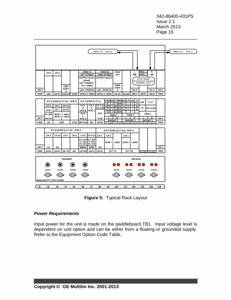
Pre-installation Visually check the unit for damage. Ensure that the jumper P2 (applicable to B86431-4X units) is in Normal position and the screws are in place and firmly tightened. Keep the shipping containers and packing materials for future use. If a unit is damaged, file a claim with the shipping agent or the local GE Multilin representative. Shelf Position The Power Units are normally installed in both the 1st and 15th shelf slots of each JungleMUX shelf. Power Units are paralleled so in the event of single unit failure the shelf power is maintained. If necessary, an additional (third) Power Unit can be installed in the shelf. The power buses of multiple shelves belonging to the same JungleMUX node can be paralleled (refer to the 86430 Equipment Shelf TPIM). It is recommended that no more than six Power Units be paralleled. A typical rack layout is shown in Figure 5.
342-86400-431PS Issue 2.1 March 2013 Page 15
Copyright GE Multilin Inc. 2001-2013
J1 J15J2 J3 J4 J5 J6 J7 J8 J9 J10 J11 J12 J13 J14
CCT1 CCT2 CCT3 CCT4
TRANSMIT RECEIVE
86429-M2 DTT TEST PANEL
CCT1 CCT2 CCT3 CCT4
PWR
130 V
4W2W FXS PWR
130 V
HCBCDR
CONTACT
I/O
S 1x SHR
JIFPORT 2 JIF-SHARE
L R
CH 1
CH 7
CH 13
CH 19
CH 2
JVT-S (PAIR 3) VT-1xJVT-Q (PAIR 3) VT-14x: SITE G
CH 4
R
CH 3
R
PAIR 2
QUAD-DS1 QUAD-DS1
-
JIFPORT 2
JVT VT
1
MODEL/R
L R
SITE B SITE C
BC96 TX: 0041
R 2R 10x TIE
Q 3R 14x STD
P 4R 15x STD
PAIR 3
JIF-SHARE
PWR
130 V
PWR
130 V
2W TO 4W OCUDP DATA
JVT-Q (PAIR 3) VT-14x: SITE G
BC96 RX: 0014
CH 4
BLANK
BC96
TX: 0158
RX: 0815
CH 5
56kb/s
CH 6
slot
CH 8-12
NX64
CH 2 CH 14
LS
DATA
HS
DATA
JVT-P (PAIR 3) VT-15x: SITE H
DTT RXDTT TX
CH 1 CH 1
BC96 TX: 0023
CH 2
HS
DATA
BC96 RX: 0032
VT 22x TO 28x
PAIR 1
1 TO 7
JIFPORT 1
L R
ETHER-10
slot
BLANK
ETHER-10
CH 5
L
SITE D
S 7xL
DS1 VT
5
L/R
R 6R 8x
Q 7R 9x
- -- -
slot
DATA
CH 1 (L)
CH 2 (R)
PTM
RTU
PWR
130 V
PWR
130 V
JMUX SERV JMUX
OC-3 OC-3
L R
SITE BFIBRE TO: SITE CFIBRE TO:
O/W VM-40
CBW
PORT
A
“BB”
RING: 1
NODE: 1 “AA”
4W PL BLANK
VNA#
m37
MPEG-4 VIDEO
VNA# 17
SYNC MODE
NORMAL, LEFT
CH 1 CH 2
MPEG-4 VIDEO
m37, VPORT#2
OUTPUT (BOOT):
VNA#5
(24TH STREET)
CV1, 8Mb/s
m37, VPORT#1
BLANK
CBW
PORT
B
ETHER-100
22ND STREET
VNA# 16
MAIN STREET
-
OUTPUT (BOOT):
CCT ADR
TX: 0304
RX: 0403
CCT ADR
TX: 0102
RX: 0201
J1 J15J2 J3 J4 J5 J6 J7 J8 J9 J10 J11 J12 J13 J14J1 J15J2 J3 J4 J5 J6 J7 J8 J9 J10 J11 J12 J13 J14
CCT1 CCT2 CCT3 CCT4
TRANSMIT RECEIVE
86429-M2 DTT TEST PANEL
CCT1 CCT2 CCT3 CCT4
PWR
130 V
4W2W FXS PWR
130 V
HCBCDR
CONTACT
I/O
S 1x SHR
JIFPORT 2 JIF-SHARE
L R
CH 1
CH 7
CH 13
CH 19
CH 2
JVT-S (PAIR 3) VT-1xJVT-Q (PAIR 3) VT-14x: SITE G
CH 4
R
CH 3
R
PAIR 2
QUAD-DS1 QUAD-DS1
-
JIFPORT 2
JVT VT
1
MODEL/R
L R
SITE B SITE C
BC96 TX: 0041
R 2R 10x TIE
Q 3R 14x STD
P 4R 15x STD
PAIR 3
JIF-SHARE
PWR
130 V
PWR
130 V
2W TO 4W OCUDP DATA
JVT-Q (PAIR 3) VT-14x: SITE G
BC96 RX: 0014
CH 4
BLANK
BC96
TX: 0158
RX: 0815
CH 5
56kb/s
CH 6
slot
CH 8-12
NX64
CH 2 CH 14
LS
DATA
HS
DATA
JVT-P (PAIR 3) VT-15x: SITE H
DTT RXDTT TX
CH 1 CH 1
BC96 TX: 0023
CH 2
HS
DATA
BC96 RX: 0032
VT 22x TO 28x
PAIR 1
1 TO 7
JIFPORT 1
L R
ETHER-10
slot
BLANK
ETHER-10
CH 5
L
SITE D
S 7xL
DS1 VT
5
L/R
R 6R 8x
Q 7R 9x
- -- -
slot
DATA
CH 1 (L)
CH 2 (R)
PTM
RTU
PWR
130 V
PWR
130 V
JMUX SERV JMUX
OC-3 OC-3
L R
SITE BFIBRE TO: SITE CFIBRE TO:
O/W VM-40
CBW
PORT
A
“BB”
RING: 1
NODE: 1 “AA”
4W PL BLANK
VNA#
m37
MPEG-4 VIDEO
VNA# 17
SYNC MODE
NORMAL, LEFT
CH 1 CH 2
MPEG-4 VIDEO
m37, VPORT#2
OUTPUT (BOOT):
VNA#5
(24TH STREET)
CV1, 8Mb/s
m37, VPORT#1
BLANK
CBW
PORT
B
ETHER-100
22ND STREET
VNA# 16
MAIN STREET
-
OUTPUT (BOOT):
CCT ADR
TX: 0304
RX: 0403
CCT ADR
TX: 0102
RX: 0201
Figure 5: Typical Rack Layout Power Requirements Input power for the unit is made on the paddleboard TB1. Input voltage level is dependent on unit option and can be either from a floating or grounded supply. Refer to the Equipment Option Code Table.
342-86400-431PS Issue 2.1 March 2013 Page 16
Copyright GE Multilin Inc. 2001-2013
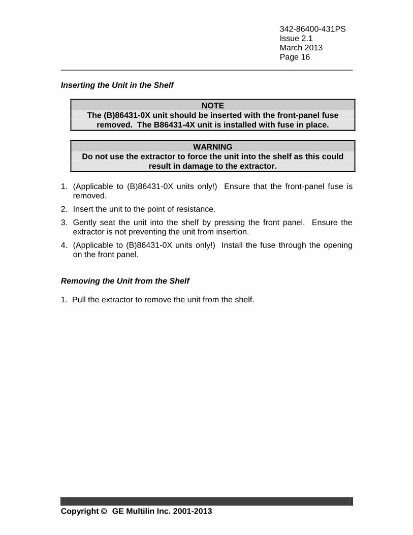
Inserting the Unit in the Shelf
NOTE
The (B)86431-0X unit should be inserted with the front-panel fuse
removed. The B86431-4X unit is installed with fuse in place.
WARNING
Do not use the extractor to force the unit into the shelf as this could
result in damage to the extractor.
1. (Applicable to (B)86431-0X units only!) Ensure that the front-panel fuse is
removed.
2. Insert the unit to the point of resistance.
3. Gently seat the unit into the shelf by pressing the front panel. Ensure the extractor is not preventing the unit from insertion.
4. (Applicable to (B)86431-0X units only!) Install the fuse through the opening on the front panel.
Removing the Unit from the Shelf 1. Pull the extractor to remove the unit from the shelf.
342-86400-431PS Issue 2.1 March 2013 Page 17
Copyright GE Multilin Inc. 2001-2013
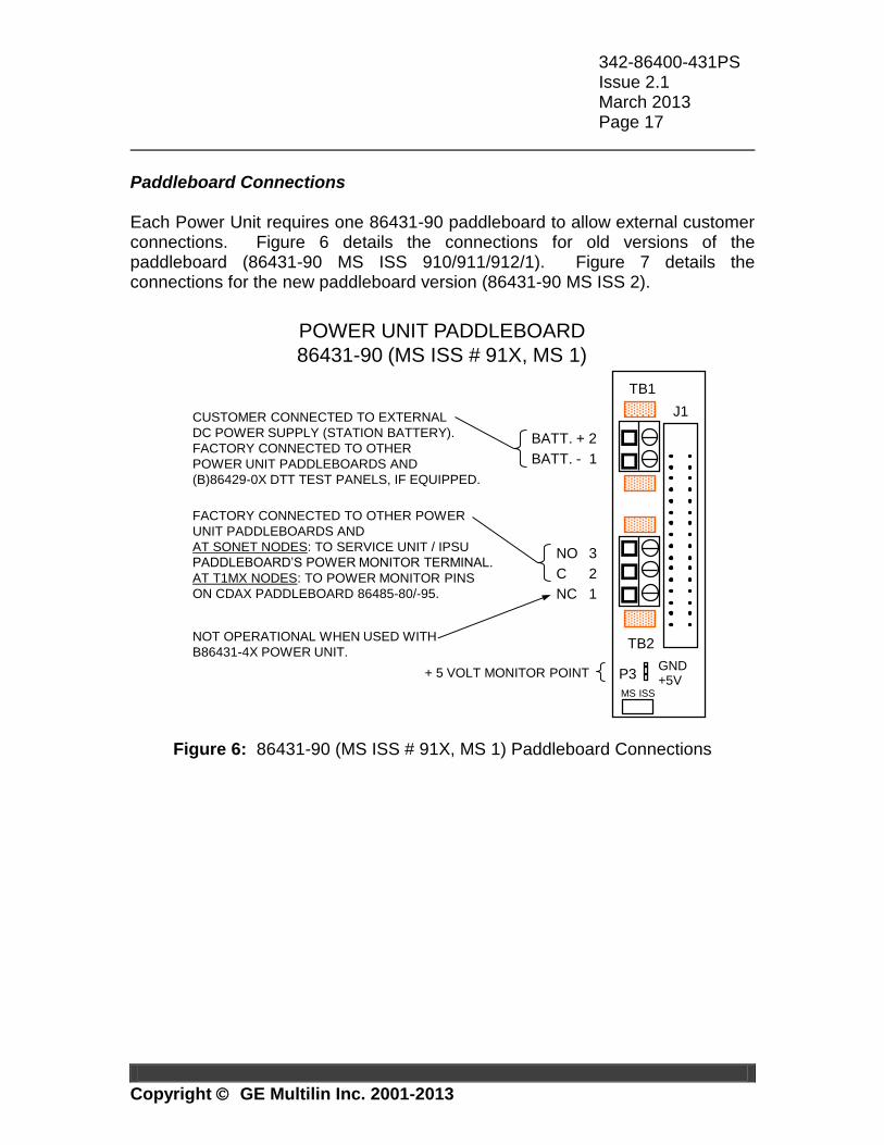
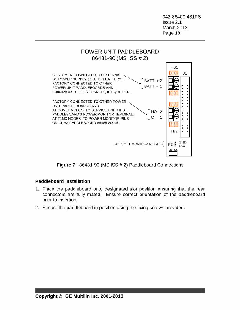
Paddleboard Connections Each Power Unit requires one 86431-90 paddleboard to allow external customer connections. Figure 6 details the connections for old versions of the paddleboard (86431-90 MS ISS 910/911/912/1). Figure 7 details the connections for the new paddleboard version (86431-90 MS ISS 2).
POWER UNIT PADDLEBOARD
86431-90 (MS ISS # 91X, MS 1)
CUSTOMER CONNECTED TO EXTERNAL
DC POWER SUPPLY (STATION BATTERY).
FACTORY CONNECTED TO OTHER
POWER UNIT PADDLEBOARDS AND
(B)86429-0X DTT TEST PANELS, IF EQUIPPED.
BATT. + 2
BATT. - 1
NO 3
+ 5 VOLT MONITOR POINT
FACTORY CONNECTED TO OTHER POWER
UNIT PADDLEBOARDS AND
AT SONET NODES: TO SERVICE UNIT / IPSU
PADDLEBOARD’S POWER MONITOR TERMINAL.
AT T1MX NODES: TO POWER MONITOR PINS
ON CDAX PADDLEBOARD 86485-80/-95.
GND+5VP3
TB1
TB2
C 2
NC 1
NOT OPERATIONAL WHEN USED WITH
B86431-4X POWER UNIT.
MS ISS
J1
Figure 6: 86431-90 (MS ISS # 91X, MS 1) Paddleboard Connections
342-86400-431PS Issue 2.1 March 2013 Page 18
Copyright GE Multilin Inc. 2001-2013
POWER UNIT PADDLEBOARD
86431-90 (MS ISS # 2)
CUSTOMER CONNECTED TO EXTERNAL
DC POWER SUPPLY (STATION BATTERY).
FACTORY CONNECTED TO OTHER
POWER UNIT PADDLEBOARDS AND
(B)86429-0X DTT TEST PANELS, IF EQUIPPED.
BATT. + 2
BATT. - 1
NO 2
FACTORY CONNECTED TO OTHER POWER
UNIT PADDLEBOARDS AND
AT SONET NODES: TO SERVICE UNIT / IPSU
PADDLEBOARD’S POWER MONITOR TERMINAL.
AT T1MX NODES: TO POWER MONITOR PINS
ON CDAX PADDLEBOARD 86485-80/-95.
J1
TB1
TB2
C 1
+ 5 VOLT MONITOR POINTGND+5VP3
MS ISS
Figure 7: 86431-90 (MS ISS # 2) Paddleboard Connections
Paddleboard Installation
1. Place the paddleboard onto designated slot position ensuring that the rear connectors are fully mated. Ensure correct orientation of the paddleboard prior to insertion.
2. Secure the paddleboard in position using the fixing screws provided.
342-86400-431PS Issue 2.1 March 2013 Page 19
Copyright GE Multilin Inc. 2001-2013
6. MAINTENANCE and TROUBLESHOOTING
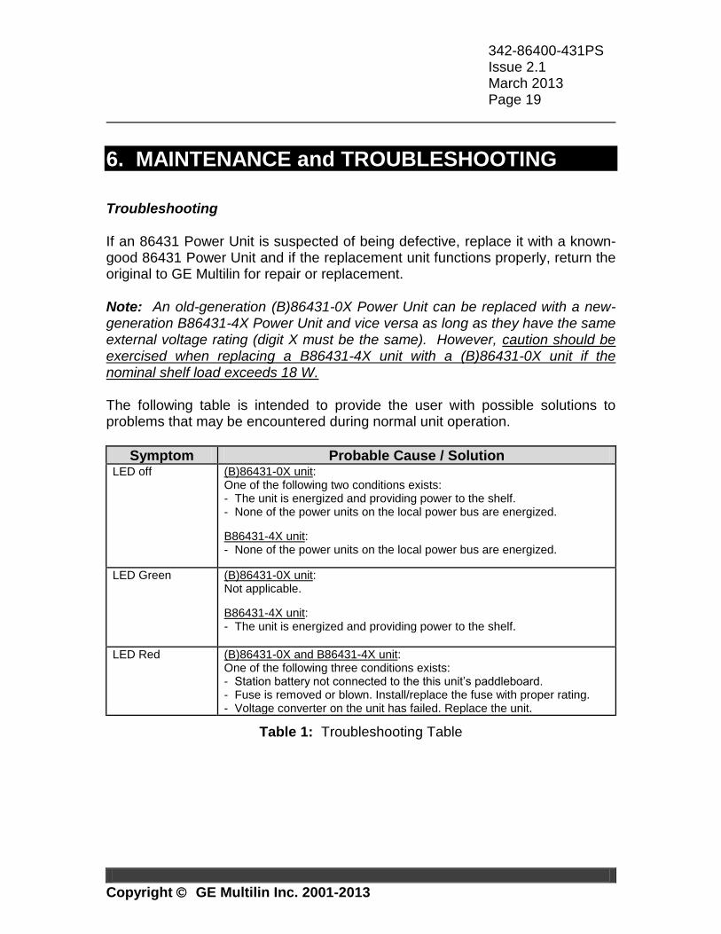
Troubleshooting If an 86431 Power Unit is suspected of being defective, replace it with a known-good 86431 Power Unit and if the replacement unit functions properly, return the original to GE Multilin for repair or replacement.
Note: An old-generation (B)86431-0X Power Unit can be replaced with a new-generation B86431-4X Power Unit and vice versa as long as they have the same external voltage rating (digit X must be the same). However, caution should be exercised when replacing a B86431-4X unit with a (B)86431-0X unit if the nominal shelf load exceeds 18 W. The following table is intended to provide the user with possible solutions to problems that may be encountered during normal unit operation.
Symptom Probable Cause / Solution LED off (B)86431-0X unit:
One of the following two conditions exists: - The unit is energized and providing power to the shelf. - None of the power units on the local power bus are energized.
B86431-4X unit: - None of the power units on the local power bus are energized.
LED Green (B)86431-0X unit: Not applicable.
B86431-4X unit: - The unit is energized and providing power to the shelf.
LED Red (B)86431-0X and B86431-4X unit: One of the following three conditions exists: - Station battery not connected to the this unit’s paddleboard. - Fuse is removed or blown. Install/replace the fuse with proper rating. - Voltage converter on the unit has failed. Replace the unit.
Table 1: Troubleshooting Table
342-86400-431PS Issue 2.1 March 2013 Page 20
Copyright GE Multilin Inc. 2001-2013
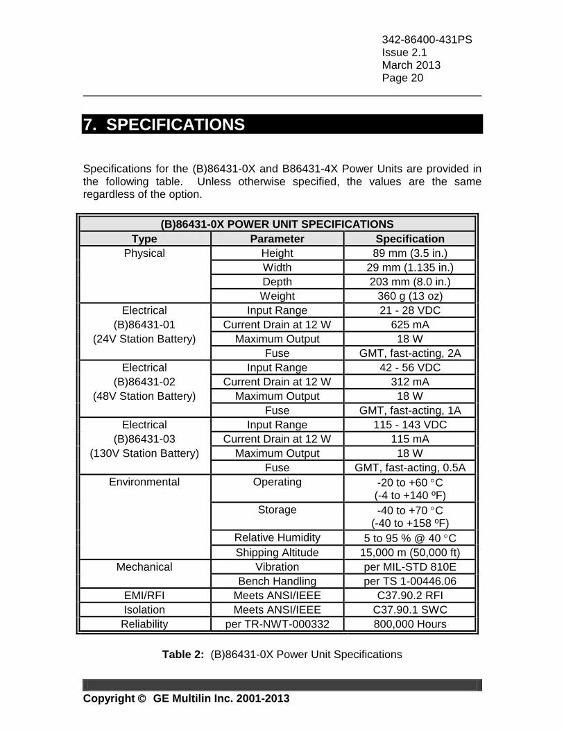
7. SPECIFICATIONS Specifications for the (B)86431-0X and B86431-4X Power Units are provided in the following table. Unless otherwise specified, the values are the same regardless of the option.
(B)86431-0X POWER UNIT SPECIFICATIONS
Type Parameter Specification
Physical Height 89 mm (3.5 in.)
Width 29 mm (1.135 in.)
Depth 203 mm (8.0 in.)
Weight 360 g (13 oz)
Electrical Input Range 21 - 28 VDC
(B)86431-01 Current Drain at 12 W 625 mA
(24V Station Battery) Maximum Output 18 W
Fuse GMT, fast-acting, 2A
Electrical Input Range 42 - 56 VDC
(B)86431-02 Current Drain at 12 W 312 mA
(48V Station Battery) Maximum Output 18 W
Fuse GMT, fast-acting, 1A
Electrical Input Range 115 - 143 VDC
(B)86431-03 Current Drain at 12 W 115 mA
(130V Station Battery) Maximum Output 18 W
Fuse GMT, fast-acting, 0.5A
Environmental Operating -20 to +60 C (-4 to +140 ºF)
Storage -40 to +70 C (-40 to +158 ºF)
Relative Humidity 5 to 95 % @ 40 C
Shipping Altitude 15,000 m (50,000 ft)
Mechanical Vibration per MIL-STD 810E
Bench Handling per TS 1-00446.06
EMI/RFI Meets ANSI/IEEE C37.90.2 RFI
Isolation Meets ANSI/IEEE C37.90.1 SWC
Reliability per TR-NWT-000332 800,000 Hours
Table 2: (B)86431-0X Power Unit Specifications
342-86400-431PS Issue 2.1 March 2013 Page 21
Copyright GE Multilin Inc. 2001-2013
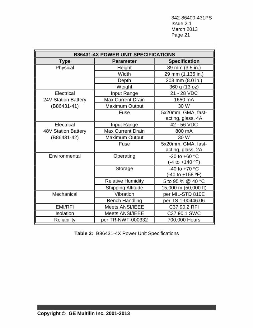
B86431-4X POWER UNIT SPECIFICATIONS
Type Parameter Specification
Physical Height 89 mm (3.5 in.)
Width 29 mm (1.135 in.)
Depth 203 mm (8.0 in.)
Weight 360 g (13 oz)
Electrical Input Range 21 - 28 VDC
24V Station Battery Max Current Drain 1650 mA
(B86431-41) Maximum Output 30 W
Fuse 5x20mm, GMA, fast-acting, glass, 4A
Electrical Input Range 42 - 56 VDC
48V Station Battery Max Current Drain 800 mA
(B86431-42) Maximum Output 30 W
Fuse 5x20mm, GMA, fast-acting, glass, 2A
Environmental Operating -20 to +60 C (-4 to +140 ºF)
Storage -40 to +70 C (-40 to +158 ºF)
Relative Humidity 5 to 95 % @ 40 C
Shipping Altitude 15,000 m (50,000 ft)
Mechanical Vibration per MIL-STD 810E
Bench Handling per TS 1-00446.06
EMI/RFI Meets ANSI/IEEE C37.90.2 RFI
Isolation Meets ANSI/IEEE C37.90.1 SWC
Reliability per TR-NWT-000332 700,000 Hours
Table 3: B86431-4X Power Unit Specifications
342-86400-431PS Issue 2.1 March 2013 Page 22
Copyright GE Multilin Inc. 2001-2013
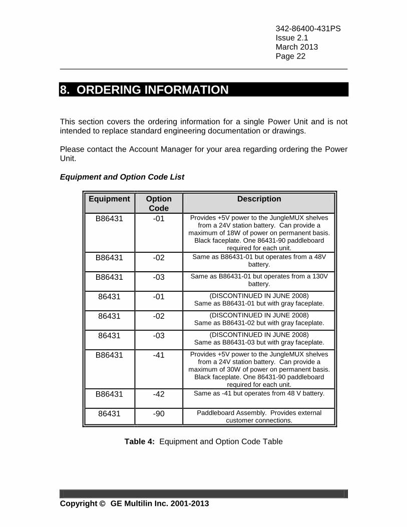
8. ORDERING INFORMATION This section covers the ordering information for a single Power Unit and is not intended to replace standard engineering documentation or drawings. Please contact the Account Manager for your area regarding ordering the Power Unit.
Equipment and Option Code List
Equipment Option
Code
Description
B86431 -01
Provides +5V power to the JungleMUX shelves from a 24V station battery. Can provide a
maximum of 18W of power on permanent basis. Black faceplate. One 86431-90 paddleboard
required for each unit.
B86431 -02
Same as B86431-01 but operates from a 48V battery.
B86431 -03
Same as B86431-01 but operates from a 130V battery.
86431 -01
(DISCONTINUED IN JUNE 2008) Same as B86431-01 but with gray faceplate.
86431 -02
(DISCONTINUED IN JUNE 2008) Same as B86431-02 but with gray faceplate.
86431 -03
(DISCONTINUED IN JUNE 2008) Same as B86431-03 but with gray faceplate.
B86431 -41
Provides +5V power to the JungleMUX shelves from a 24V station battery. Can provide a
maximum of 30W of power on permanent basis. Black faceplate. One 86431-90 paddleboard
required for each unit.
B86431 -42
Same as -41 but operates from 48 V battery.
86431 -90 Paddleboard Assembly. Provides external customer connections.
Table 4: Equipment and Option Code Table
342-86400-431PS Issue 2.1 March 2013 Page 23
Copyright GE Multilin Inc. 2001-2013
APPENDIX A
LIST OF ILLUSTRATIONS List of Figures
FIGURE DESCRIPTION PAGE
Figure 1: B86431-03 Front Panel Layout ....................................................... 8 Figure 2: B86431-42 Front Panel Layout ....................................................... 9 Figure 3: (B)86431-0X Power Unit Block Diagram ....................................... 12
Figure 4: B86431-4X Power Unit Block Diagram ......................................... 13 Figure 5: Typical Rack Layout ...................................................................... 15
Figure 6: 86431-90 (MS ISS # 91X, MS 1) Paddleboard Connections ........ 17 Figure 7: 86431-90 (MS ISS # 2) Paddleboard Connections ....................... 18
List of Tables
TABLE DESCRIPTION PAGE
Table 1: Troubleshooting Table ................................................................... 19
Table 2: (B)86431-0X Power Unit Specifications ......................................... 20 Table 3: B86431-4X Power Unit Specifications ............................................ 21 Table 4: Equipment and Option Code Table ................................................ 22
342-86400-431PS Issue 2.1 March 2013 Page 24
Copyright GE Multilin Inc. 2001-2013
APPENDIX B
LIST OF ACRONYMS
ANSI American National Standards Institute
C Common
CI Craft Interface
DC Direct Current
EAS Equipment Assembly Schematic
EIA Electronic Industries Association
EMI Electromagnetic Interference
ESDS Electrostatic Discharge Sensitive
IEEE Institute of Electrical and Electronics Engineers
LED Light Emitting Diode MS ISS Manufacturing Standard Issue MTBF Mean Time Between Failures
NAD Node Assignment Drawing
NC Normally Closed
NO Normally Open
P/B Paddleboard
RFI Radio Frequency Interference
SONET Synchronous Optical Network
SWC Surge Withstand Capability
TPIM Technical Practice and Installation Manual


![BDIO03 [Re im kompatibility] - umel.feec.vutbr.cz · Doc. Ing. Lukáš Fujcik, Ph.D. Základní invertor v technologii CMOS dva tranzistory: T1 – vodivostní kanál typ N T2 –](https://static.dokumenty.site/doc/80x56/5b61b4377f8b9a09498cb8af/bdio03-re-im-kompatibility-umelfeecvutbrcz-doc-ing-lukas-fujcik.jpg)


