83
YARNMASTER ® ZENIT Instruction Manual LZE 044843.003en
| Date post: | 30-Oct-2015 |
| Category: |
Documents |
| Upload: | kashif-xahir-khan |
| View: | 796 times |
| Download: | 120 times |

7/16/2019 YM Zenit Manual-LZE 044843 003en
http://slidepdf.com/reader/full/ym-zenit-manual-lze-044843-003en 1/83
YARNMASTER ®
ZENITInstruction Manual
LZE
044843.003en

7/16/2019 YM Zenit Manual-LZE 044843 003en
http://slidepdf.com/reader/full/ym-zenit-manual-lze-044843-003en 2/83
7/16/2019 YM Zenit Manual-LZE 044843 003en
http://slidepdf.com/reader/full/ym-zenit-manual-lze-044843-003en 3/83
Loepe Brothers Ltd.
Kastellstrasse 10
P. O. Box 582
CH-8623 Wetzikon/Switzerland
Phone +41 43 488 11 11
Fax +41 43 488 11 00
E-Mail [email protected]
Internet www.loepe.com
YarnMaster® is a registered trademark o Loepe Brothers
Ltd. or Switzerland and other countries.
All urther company and product names are trading names orregistered trademarks o the relative companies.
The content o this Operating Instruction is protected by copy-
right. All rights reserved. No part o this may be reproduced in
whatever orm (by printing, photocopying, microilm or other)
without a written grant o Loepe Brothers Ltd., nor may it be
processed or distributed by any electronic mean.
Copyright© 2010 Loepe Brothers Ltd., Switzerland
06.2011 / Version ≥ 2.3.2.3

7/16/2019 YM Zenit Manual-LZE 044843 003en
http://slidepdf.com/reader/full/ym-zenit-manual-lze-044843-003en 4/83
7/16/2019 YM Zenit Manual-LZE 044843 003en
http://slidepdf.com/reader/full/ym-zenit-manual-lze-044843-003en 5/83
ZENIT 5
TABLE OF CONTENTS
Table of Contents
Safety Instructions 7
Norms and Regulations 7
Instruction Manual 7
Liability 7
Operational Notes 8
Yarn Clearing (General) 9
Deinition o Yarn Faults 9
Yarn Fault Classiication 11
Yarn Clearing 12
Foreign Matter (F) 15
Synthetic Foreign Matter (P) 15
Variable CV Channel (VCV ) 15
Imperections 16
Surace Index SFI 16
YarnMaster Zenit 17
Functional Range 17
Operating 18
Central Unit 18User Interace 19
Deining the Clearer Parameters 21
Deining the Class Settings 21
Assigning Changed Settings 22
Print 23
Adjust 24
Dialog 26
Sotware 26
Language 26
Reports 26
Reboot System 26
Machine 26
Central Unit 26
Date / Time 26
Access Level / Password 27
Configuration 28
System 28
Section 29

7/16/2019 YM Zenit Manual-LZE 044843 003en
http://slidepdf.com/reader/full/ym-zenit-manual-lze-044843-003en 6/83
6 ZENIT
TABLE OF CONTENTS
Group 30
Samples 31
Style (Style Memory) 32
Base Settings 34
Repetitions 34
Pilot Spindles 35
Data Acquisition 35
Reset Data 35
Diameter Base (Group) 36
Fine Adjust 36
Special Functions 37
Coniguration Codes 38Test Mode 39
Yarn Structure 42
Channel 42
O Count 43
Short O Count 43
Yarn Count 44
Short/Long/Thin Cluster 44
SFI/D (Option) 46
VCV (Option) 47
Splice 48
MM Lot 49
Setting Examples (Standard Values) 50
Class Clearing 51
Foreign Matter (F) 53
F Class Settings 53
F Cluster Settings 54
P Settings 55
Monitoring Data 56
Cut Data 56
Selection 57
Cut Declaration 57
Variable CV (Option) 59
Surace Index SFI (Option) 59
Imperections IPI (Option) 60
Class Data 61
Class Clearing Data 61
F Clearing Data 62
Splice Classiication Data 62
Chart 63
Shift Calendar 64
Diagnosis 65
AWE Zenit State / Adjust Parameters 65
AWE Command 65
Diameter Base (Spindle) 65
Spindle Adjust 65Cut Declaration 65
Reports and Diagnosis 66
Checks and Maintenance 70
General 70
Daily 70
Weekly 70
Cleaning the Optics 71
Replacement o AWE or Sensing Head 71
Service Functions 72
Screen Calibration 72
Change o IP Address 72
Factory Reset 73
Reset o Fine Adjust Values 73
Clearer Components 74
Central Unit LZE- II 74
Central Unit LZE- III 75
Sensing Head 76
Yarn Count Rage (Optical scanning principle) 76
Sensing Head Display (7-Segment Display) 77
Mounting o P-Sensors 77
Technical Data 78
7/16/2019 YM Zenit Manual-LZE 044843 003en
http://slidepdf.com/reader/full/ym-zenit-manual-lze-044843-003en 7/83
ZENIT 7
SAFETY INSTRUCTIONS
Safety Instructions
Norms and Regulations
The LOEPFE YarnMaster Zenit yarn clearing system is a prod-
uct which has been inspected or technical saety. It complies
with the ollowing directives:
2006/42/EC Machinery Directive
2006/95/EC Low Voltage Directive
2004/108/EC Electromagnetic Compatibility
Instruction Manual
To prevent aults and operating errors, we recommend to
careully read this Instruction Manual and to careully ollow
the instructions given.
!Indicates warnings which, if not properly observed,
could harm your health, impair the functioning of
the equipment or the security of your data.
Note : The screen representations in this manual serve as illus-
tration only. They should not be used as setting examples!
A copy o this Instruction Manual must be kept easily acces-
sible near the machine.
Liability
The manuacturer assumes no liability or damage caused by:
Noncompliance with the saety, operating and mainte-
nance instructions contained in this Manual.
The use o spare parts / non-OEM parts / conversion parts
not supplied by us.
Unauthorized conversion and modiication o the yarn
clearer.
Normal wear.

7/16/2019 YM Zenit Manual-LZE 044843 003en
http://slidepdf.com/reader/full/ym-zenit-manual-lze-044843-003en 8/83
8 ZENIT
SAFETY INSTRUCTIONS
!
!
!
!
Operational Notes
This yarn clearing equipment must only be installed, initiated
and operated by trained personnel. Improper operation o the
equipment could cause hazards.
In accordance with 2006/42/EC, 2006/95/EC, 2004/108/EC
this yarn clearing installation should only be operated with the
covers closed (cooling, ire protection, contamination, spark
intererence etc.)
This yarn clearing equipment must only be operated with
the standard power supply (voltage/cycles) with ground con-
nection.
AC 110V 60Hz 3.15 A -15%/+20%
AC 230V 50Hz 3.15 A ±15%
As per other inormation by the machinery manuacturer,
however, with ground connection and with an isolation
transormer which complies with the requirements o DIN
EN 61558.
The ON/OFF switch does not disconnect the equipment
from the mains voltage! Failure to comply with this
warning can result in death or severe injuries.
Beore opening, modiying or completing the equipment,
disconnect the mains plug rom the grounded power supply
socket or turn o the master switch o the winding machine.
This yarn clearer system may be connected to the power sup-
ply only ater installation o all ront panels, plug-in boards and
provided covers, in particular o the central unit.
Under certain conditions, high temperatures may occur at the
power print o the control station. Check the temperature be-
ore touching the cooling rips.
The knives at the sensing heads are automatically activated.
Beware o touching the knives, you could be injured.
Electronic components and assemblies (printed circuit
boards) are endangered by electrostatic charges! Be-
ware o touching the soldered connectors, pin contacts, print-
ed circuits or electronic components beore they have been
discharged statically. Hold the units at the periphery only.

7/16/2019 YM Zenit Manual-LZE 044843 003en
http://slidepdf.com/reader/full/ym-zenit-manual-lze-044843-003en 9/83
ZENIT 9
YARN CLEARING GENERAL
Yarn Clearing (General)
Definition of Yarn Faults
The spinning process supplies a relatively uniorm yarn.
However, dierences in yarn diameter cannot be completely
avoided. Thus, it is irst necessary to distinguish between
normal yarn irregularities and actual yarn aults.
Yarn faults may be deined as yarn irregularities which can
lead to diiculties in subsequent production stages or to
aults in the end product. Yarn clearing is deined as the de-
tection and elimination o yarn aults. This task is per ormed
during the winding process. Yarn clearer are, thereore, part
o a winder.
To eliminate a ault it is necessary to interrupt the windingprocess. The spindle must be stopped, the ault eliminated
and the ends o the yarn joined together again. Obviously this
interruption results in a loss o production. Yarn clearing is,
thereore, always a compromise between quality and produc-
tion, i.e. between the maximum possible number o yarn aults
which could be removed and the least acceptable production
loss. This compromise results in a distinction between:
Objectionable yarn faults, namely those which are
tolerated or sake o machine eiciency, and
Non objectionable yarn faults, aults that cannot be
tolerated.
Yarn Faults
Based on the average yarn diameter (basic diameter), the ol-
lowing yarn aults can be detected and cleared:
Thick and thin places are deined, depending on wheth-
er there is an increase or a decrease in diameter.
Within the thick places urther distinctions are made:
– Neps, as extremely short (up to a ew mm) and extre-
mely thick aults (several times the base diameter)
– Short faults, as aults o limited length (o about 0.5 to
10 cm) but o considerable thickness (1.1 to 4.0 times the
base diameter)
– Long faults and double ends, as aults o considerable
length (rom 5 to 200 cm) but o limited thickness (1.04 to
2.0 times the base diameter).
Faulty splices
Yarn count deviation (positive / negative)
Yarn count deviation (positive / negative)
in the short count range (1–32 m)
Neps
Short Faults
Long Faults
Thin Places
Splices
Yarn Count
Short Count

7/16/2019 YM Zenit Manual-LZE 044843 003en
http://slidepdf.com/reader/full/ym-zenit-manual-lze-044843-003en 10/83
10 ZENIT
YARN CLEARING GENERAL
Accumulations of Faults (Cluster)
Periodic clusters (moiré)
Non-periodic clusters
in the short, long or thin ault range which repeat them-
selves several times within a short distance.
Off-standard Bobbins (SFI / D)
Irregularities o the surace structure such as:
Hairiness
Neppiness
Irregularity
Imperections (IPI)
Yarn Irregularities (VCV)
Disturbing diameter variations or sporadic irregularities, or
example:
Neppiness
Irregularity (CV)
Imperections (IPI)
Check length adjustable between 1–50 m
Foreign Matter (F)
Foreign matter with a color that is dierent rom the base
color o the yarn:
Bright oreign matter in the dyed yarn
Dark oreign matter in the raw-white yarn
Even the smallest contrast dierences are reliably detect-
ed in colored yarns.
Synthetic Foreign Matter (P)
Synthetic oreign matter (e.g. polypropylene)
Irrespective o the color o the yarn and the oreign
matter, or example, white and transparent polypropyl-ene in raw-white yarn
In dyed or colored yarn In raw-white yarn
Periodic
Non-periodic
Hairiness
Neppiness
Irregularity
Imperfections
Neppiness
Irregularity
Imperfections
Synthetic foreign matter in raw-white yarn
7/16/2019 YM Zenit Manual-LZE 044843 003en
http://slidepdf.com/reader/full/ym-zenit-manual-lze-044843-003en 11/83
ZENIT 11
YARN CLEARING GENERAL
Figure 1
D i a m
e t e r Y
Length X
Figure 2
Length
Figure 3
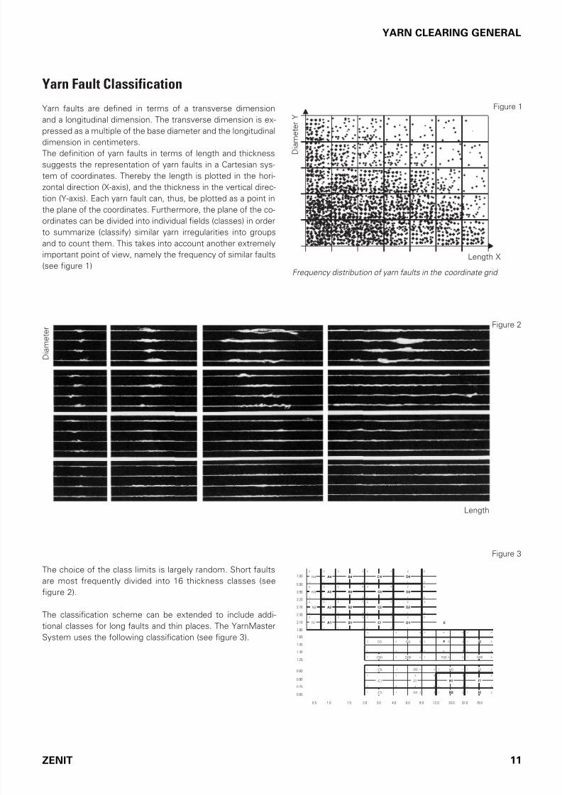
Yarn Fault Classification
Yarn aults are deined in terms o a transverse dimension
and a longitudinal dimension. The transverse dimension is ex-
pressed as a multiple o the base diameter and the longitudinal
dimension in centimeters.
The deinition o yarn aults in terms o length and thickness
suggests the representation o yarn aults in a Cartesian sys-
tem o coordinates. Thereby the length is plotted in the hori-
zontal direction (X-axis), and the thickness in the vertical direc-
tion (Y-axis). Each yarn ault can, thus, be plotted as a point in
the plane o the coordinates. Furthermore, the plane o the co-
ordinates can be divided into individual ields (classes) in order
to summarize (classiy) similar yarn irregularities into groups
and to count them. This takes into account another extremely
important point o view, namely the requency o similar aults
(see igure 1)Frequency distribution of yarn faults in the coordinate grid
The choice o the class limits is largely random. Short aults
are most requently divided into 16 thickness classes (see
igure 2).
The classiication scheme can be extended to include addi-
tional classes or long aults and thin places. The YarnMaster
System uses the ollowing classiication (see igure 3).
D i a m e t e r
2 2 2 4 2 4 2 8
1 1 1 3 1 3 1 7
2 2 2 4 2 4 2 6
1 1 1 3 1 3 1 5
2 2 2 4 2 4 2 4
1 1 1 3 1 3 1 3
2 2 2 4 2 4 2 2
1 1 1 3 1 3 1 1
3 3 6 3 6 9 3 6
2 2 5 2 5 8 2 5
1 1 4 1 4 7 1 4
1 1 2 1 2 3 1 2
1 1 2 3 1 2 1 2
1 1 3 5 1 3 1 3
2 2 4 6 2 4 2 4
1 1 2 3 1 2 1 2
N4 A4 B4 C4 D4
N3
N2
N1
A3 B3 C3 D3
D2A2 B2 C2
A1 B1 C1 D1
C0 F G
G00F00C00 D00
-C0 -D0
-D1
H0
-C1 H1
I0
I1
I2H2-D2-C2
D0
E
7.00
5.00
3.90
3.20
2.70
2.30
2.10
1.80
1.60
1.45
1.30
1.20
0.83
0.80
0.75
0.65
0.5 1.0 1.5 2.0 3.0 4.0 6.0 8.0 12.0 20.0 32.0 70.0

7/16/2019 YM Zenit Manual-LZE 044843 003en
http://slidepdf.com/reader/full/ym-zenit-manual-lze-044843-003en 12/83
12 ZENIT
YARN CLEARING GENERAL
As already mentioned, various types o yarn aults are distin-
guished according to their orm. In the plane o coordinates it
is possible to distinguish areas which relate to the ollowing
types o aults (see igure 4).
Neps Thick places / Short faults
Long faults and
Double ends
Thin places
Figure 4
Figure 5
D i a m e t e r
Length
RG
Yarn Clearing
Base Curve
The distinction between yarn aults which are to be cut out
and those which are to be let in the yarn (unacceptable and
acceptable yarn aults), which is made in the interest o win-
der eiciency, has already been pointed out. This distinction
can be represented graphically on the plane o coordinates as
a line which separates the acceptable aults (below) rom the
unacceptable ones (above). This line represents the theore-
tically-desirable base curve (RG). A concave base curve
(see igure 5) normally corresponds to the requirements in
practice.
The concave shape arises rom the textile evaluation, where-
by the greater the deviation in diameter that is tolerated, the
smaller the length deviation that appears acceptable. Fur-thermore, the base curve, thus, passes through ields o sim-
ilar ault requencies, which meets the requirement o high
eiciency.
A distinction must be made between the theoretically-desir-
able base curve and the practically-achievable base curve,
which depends on the one hand on the clearing characteristic
typical o a clearer type, and, on the other hand, on its set-
ting lexibility.

7/16/2019 YM Zenit Manual-LZE 044843 003en
http://slidepdf.com/reader/full/ym-zenit-manual-lze-044843-003en 13/83
ZENIT 13
YARN CLEARING GENERAL
Clearer Characteristics
Clearer characteristics are the basic pattern o the base curve,
this pattern being typical o a particular clearer type. Impor-
tant actors in assessing a clearer are the shape o this base
curve on the one hand, and the possibility o changing this
curve on the other hand.
The corresponding clearer setting:
N = 6.0 Diameter limit or neps
DS = 2.40 Diameter limit or short aults
LS = 1.3 Limit or short ault length
DL = 1.25 Diameter limit or long aults and double ends
LL = 40 Limit or long ault length
-D = -20% Limit o the diameter decrease or thin places
-L = 60 Limit or thin place length
All diameter limits reer to the reerence yarn diameter
(base).
Clearing According to Classes
Yarn Faults
Clearing according to classes allows or the creation o com-
pletely optional clearer characteristics. This is advantageous,
especially or ancy yarns.
The use o class clearing in combination with conventional
clearing oten achieves better results when short and long
aults occur at the same time.
Splices
Clearing according to splice classes allows or the creation o
completely optional splice detection. An advantage or ancy
yarn, core-spun yarn etc.
Graphic presentation of clearing curve

7/16/2019 YM Zenit Manual-LZE 044843 003en
http://slidepdf.com/reader/full/ym-zenit-manual-lze-044843-003en 14/83
14 ZENIT
YARN CLEARING GENERAL
Short Fault and Long Fault Combined
Exact inspection o a yarn ault shows that it changes along
the longitudinal dimension. A thick place is made up o a com-
bination o dierent thickenings.
For classiication, this ault is only characterized ater it has
completely run through the measuring ield o the sensing
head.
The dierent cross dimensions o the long ault are calculated
as a mean value. The average thickening is then lower relative
to the largest cross-dimension o the yarn ault. Thereore the
yarn ault is assigned to the long ault class.
Depending on the yarn and the selected setting it is thereore
possible that, at simultaneous short and long aults, the sum
o the cut short and long aults in menu Monitoring Data andthe sum o the cut short and long aults in menu Class Data
show dierences.
For simultaneous short and long aults it is recommended to
apply the class clearing in combination with the conventional
clearing. Better results can thus be achieved.
Characterized as short
when cleared according to channels
Base curve set
with respect to short
Characterized as long during classification

7/16/2019 YM Zenit Manual-LZE 044843 003en
http://slidepdf.com/reader/full/ym-zenit-manual-lze-044843-003en 15/83
ZENIT 15
YARN CLEARING GENERAL
Foreign Matter (F)
The classiication o oreign matter is based on the evaluation
o dierences in contrast.
Foreign matters are classiied as ollows: The length class-
es on the horizontal axis are divided into S–I–R–O, the dark-
ness levels on the vertical axis into 1–2–3–4. In addition, each
class is divided into our subclasses. (= total 128 classes).
The darkness scale is divided into a positive area (darker color
positions) and a negative area (or brighter color positions).
Synthetic Foreign Matter (P) The detection o synthetic oreign matter as polypropylene,
polyamide (nylon) etc. is based on Triboelectricity. The dier-
ent electrical charging o materials (e.g. cotton and polypro-
pylene) caused by the winding process is evaluated.
Triboelectric Effect
The triboelectric eect is an electrical phenomenon
where certain materials become electrically charged ater
coming into contact with another, dierent, material.
The polarity and strength o the charges produced dier
according to material and surace smoothness.
That means: The urther the materials lie o each other in the
triboelectric series, the more deinitely they can be detected.
Variable CV Channel (VCV)
Disturbing diameter variations caused by drat aults, soiled
cylinders or sporadically occurring irregularities can be de-
tected.
As opposed to laboratory practice where check lengths o
400 or 1000 m are normally used or CV determination, the
check length o the VCV can be varied continuously between
1 and 50 m. This allows or the speciic detection o diameter
variations in this length range.
The clearer calculates continuously the VCV values rom the
yarn pieces with the set check length and compares these
with its loating mean value.
Note : These values cannot be compared with the optical CV
values of the Statistics or the data collected in the laboratory
because the check lengths as well as the cutting lengths for
calculation are different.
Dark
Bright
2 4 2 4 2 4 2 4
1 3 1 3 1 3 1 3
2 4 2 4 2 4 2 4
1 3 1 3 1 3 1 3
2 4 2 4 2 4 2 4
1 3 1 3 1 3 1 3
2 4 2 4 2 4 2 4
1 3 1 3 1 3 1 3
1 3 1 3 1 3 1 3
2 4 2 4 2 4 2 4
1 3 1 3 1 3 1 3
2 4 2 4 2 4 2 4
1 3 1 3 1 3 1 3
2 4 2 4 2 4 2 4
1 3 1 3 1 3 1 3
2 4 2 4 2 4 2 4
BS1 BI1 BR1 BO1
BO2
BO3
BO4
BR2
BR3
BR4
BI2
BI3
BI4
BS2
BS3
BS4
DS4
DS3
DS2
DS1
DI4
DI3
DI2
DI1
DR4
DR3
DR2
DR1
DO4
DO3
DO2
DO1
1
2
3
4
ORIS
4
3
2
1
Dry Human Hands, Skin
Leather
Rabbit Fur
Glass
Human Hair
Nylon (Polyamid)
Wool
Fur
Lead
Silk
Aluminium
Paper
cotton
Steel
Wood
AmberHard Rubber
Nickel, Copper
Brass, Silver
Gold, Platinum
Polyester
Saran Wrap
Polyacrylic
Polyurethane
Polyethylene (scotch tape)
Polypropylene
Aquires a morepositive harge
+
+
-
–Aquires a morenegative harge
Triboelectric Series

7/16/2019 YM Zenit Manual-LZE 044843 003en
http://slidepdf.com/reader/full/ym-zenit-manual-lze-044843-003en 16/83
16 ZENIT
YARN CLEARING GENERAL
Imperfections
Frequent yarn aults are described as Imperections in the
language o the textile industry. It is generally acknowledged
that the shorter the ault length, or the smaller the diameter
deviation respectively, the more requent the event.
The source o these aults is ound in the raw material or in a
non-perect spinning process. The raw material, card wires,
eccentric top rollers/bottom rollers, deective aprons, rings
and ring travellers have a signiicant inluence on the imper-
ections.
With a reliable analysis o the Imperections it is not only
possible to optimize the production process but also con-
clusions can be drawn concerning the quality o the used
ibre material.
20 70 cm
0.5 1 2 4 8 cm
D 5.00
D 3.20
D 2.30
D 1.81
D 1.28
D 0.89D 0.75
D 1.11
Surface Index SFI
The monitoring and evaluation o the surace structure o a
yarn (e.g. hairiness), is a urther important criterion or qual-
ity assurance.
In order to predict yarn behavior during processing in weav-
ing or knitting, it is not suicient to simply consider individual
quality characteristics (e.g. yarn irregularity) to assess a yarn.
Only a combination o dierent quality criteria (e.g. hairiness
and irregularity) supports making a deinite conclusion.
These quality characteristics are combined in the surace in-
dex SFI enabling the user to monitor the quality level easily
and eiciently.
Frequent events Neps Thick Places
Thin Places
Very frequent events Small

7/16/2019 YM Zenit Manual-LZE 044843 003en
http://slidepdf.com/reader/full/ym-zenit-manual-lze-044843-003en 17/83
ZENIT 17
FUNCTIONAL RANGE
YarnMaster Zenit
Functional Range
P Clearing
– Clearing o Synthetic Foreign
Matters PP PE etc.
F Clearing
– Foreign Matter Class Clearing dark
and bright
– Foreign Matter Cluster Clearing
LabPack (Option)
– Imperections IPI
– Surace Index SFI
– O-Standard Bobbin Detection SFI/D
– Variable CV Channel VCV
Quality Pack
– Channel Clearing
N Neps
S Short Faults
L Long Faults
T Thin Places
– Yarn Count Channel
– Short Count Channel
– Cluster Channel Long / Short / Thin
– Class Clearing
– Classiication o Yarn Faults
– Splice Channel
– Splice Class Clearing
– Classiication o Splice Faults
YARNMASTER
ZENIT
YARNMASTER
ZENIT F
YARNMASTER
ZENIT FP

7/16/2019 YM Zenit Manual-LZE 044843 003en
http://slidepdf.com/reader/full/ym-zenit-manual-lze-044843-003en 18/83
18 ZENIT
OPERATING
Operating
Central Unit
1 Touch Screen
The central unit is operated by direct inputs on the touch-
screen. Applying light pressure on the screen surace acti-
vates the unctions shown.
Tap the menu item to be selected with the inger or a blunt,
non-metallic object.
!
Do not use a pointed, metallic object as this could
damage the monitor surface!
Cleaning
The monitor surace is made o plastic material. Clean the
monitor with a sot cloth. Heavy soiling can be cleaned with
water and soap.
!Never clean the monitor with aggressive cleaning
agents!
2 USB Port
USB port to transer reports and clearer data to a server and
printer. The USB port is protected against dust and humidity
by a removable cover.
2
1
2
7/16/2019 YM Zenit Manual-LZE 044843 003en
http://slidepdf.com/reader/full/ym-zenit-manual-lze-044843-003en 19/83
ZENIT 19
OPERATING
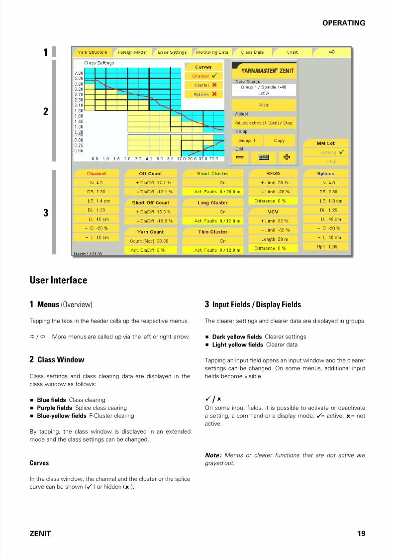
User Interface
1 Menus (Overview)
Tapping the tabs in the header calls up the respective menus.
/ More menus are called up via the let or right arrow.
2 Class Window
Class settings and class clearing data are displayed in the
class window as ollows:
Blue fields Class clearing
Purple fields Splice class cearing
Blue-yellow fields F-Cluster clearing
By tapping, the class window is displayed in an extended
mode and the class settings can be changed.
Curves
In the class window, the channel and the cluster or the splice
curve can be shown ( ) or hidden ( ).
3 Input Fields / Display Fields
The clearer settings and clearer data are displayed in groups.
Dark yellow fields Clearer settings
Light yellow fields Clearer data
Tapping an input ield opens an input window and the clearer
settings can be changed. On some menus, additional input
ields become visible.
/ On some input ields, it is possible to activate or deactivate
a setting, a command or a display mode: = active, = not
active.
Note : Menus or clearer functions that are not active are
grayed out.
3
1
2

7/16/2019 YM Zenit Manual-LZE 044843 003en
http://slidepdf.com/reader/full/ym-zenit-manual-lze-044843-003en 20/83
20 ZENIT
OPERATING
The clearer data or clearer settings o the open menu can be
saved to a USB lash drive and printed as PDF.
Group / Edit
The + or – keys or the “keyboard” called up can be used to
select a certain clearer group or spindle.
Depending on the menu, these keys are used to:
Select a clearer group or a memory to assign clearer set-
tings.
Select a clearer group to perorm an adjustment.
Select a clearer group or an individual spindle to view the
clearer settings, classiication data or production data.
4 Edit Field
Info
Menu navigation. Further steps to be perormed are displayed
as input assistance.
Data Source
Display o selected group, selected spindle or selected
style memory.
Description o spooled lot or, i not deined, description othe style.
Adjust
During the startup or the start o the lot, the clearer is cali-
brated to the new yarn. Adjustment is started, activated or
aborted here.
4

7/16/2019 YM Zenit Manual-LZE 044843 003en
http://slidepdf.com/reader/full/ym-zenit-manual-lze-044843-003en 21/83
ZENIT 21
OPERATING
Defining the Clearer Parameters
Tapping a clearer setting opens the input window and the
clearer settings can be changed. The selected input ield is
now highlighted blue.
• Change o the clearer settings via the displayed keyboard:
The setting can now be changed directly or by scrolling
with the + or – keys. The clearer channel can be switched
o with the OFF setting.
• Continue or all clearer settings in this input widow.
• Take over the clearer settings with OK or discard themwith Cancel.
The input window is closed.
When the input ield was quit with OK, the message “ Assign to
group or style ” is displayed in the Edit ield under Ino.
The changes must now be assigned to the respective group
or style.
Defining the Class Settings
By tapping the Class Settings window, the window is dis-
played in an extended mode. The class settings can then be
changed.
• Tap the class feld. This activates or deactivates class
clearing or this feld. Blue felds, blue-yellow felds (F-
Cluster) or purple felds (Splice) mean that class clearing
is active here. The yellow felds mean that class clearing
is not active here.
• Continue until the desired class setting is reached.
• Accept the changes with OK.
The input window is closed.
I settings were changed, the message “Assign to group or
style ” is displayed in the Ino ield.
The changes must now be assigned to the respective group
or style.
7/16/2019 YM Zenit Manual-LZE 044843 003en
http://slidepdf.com/reader/full/ym-zenit-manual-lze-044843-003en 22/83
22 ZENIT
OPERATING
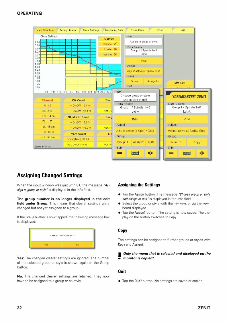
Assigning Changed Settings
When the input window was quit with OK, the message “As-
sign to group or style” is displayed in the Ino ield.
The group number is no longer displayed in the edit
field under Group. This means that clearer settings were
changed but not yet assigned to a group.
I the Group button is now tapped, the ollowing message box
is displayed:
Yes: The changed clearer settings are ignored. The number
o the selected group or style is shown again on the Group
button.
No: The changed clearer settings are retained. They now
have to be assigned to a group or an style.
Assigning the Settings
• Tap the Assign button. The message “Choose group or style
and assign or quit” is displayed in the Ino ield.
• Select the group or style with the +/– keys or via the key-
board displayed.
• Tap the Assign? button. The setting is now saved. The dis-
play on the button switches to Copy.
Copy
The settings can be assigned to urther groups or styles with
Copy and Assign?.
!Only the menu that is selected and displayed on the
monitor is copied!
Quit
•
Tap the Quit? button. No settings are saved or copied.

7/16/2019 YM Zenit Manual-LZE 044843 003en
http://slidepdf.com/reader/full/ym-zenit-manual-lze-044843-003en 23/83
ZENIT 23
OPERATING
The clearer data or clearer settings o the open menu can be
saved to a USB lash drive and printed as PDF.
!Make sure that the USB stick is virus-free. LOEPFE
assumes no liability for possible damage to the
system (loss of data etc.) that could be caused
by viruses!
• Insert the USB stick in the ront panel.
• Wait until the Print button becomes active.
• Tap the Print button and conirm the START Print Job? mes-
sage with Yes.
The PDF ile is now created and saved to the stick.
!Saving the data can take some time. Do not remove
the USB flash drive until the red warning screen dis-
appears!

7/16/2019 YM Zenit Manual-LZE 044843 003en
http://slidepdf.com/reader/full/ym-zenit-manual-lze-044843-003en 24/83
24 ZENIT
OPERATING
Adjust
Initial Startup / Change of Software
To compensate or the deviations o the individual spindles,
an automatic Spindle Adjust on all spindles is perormed
during the irst adjustment ater the startup o the equipment
or ater a sotware change.
The ollowing message box is displayed: “ Startup Adjust for
Group x”.
!During the automatic Spindle Adjust, the first 80 m of
yarn on all spindles are not cleared.
Note : If sensing heads are replaced on a machine, a manual
Spindle Adjust has to be carried out on these spindles. (See
Diagnosis menu.)
Putting into Operation / Lot Change
When putting the system into operation and or every lot
change, it must be deined how the yarn to be wound is to be
cleared, i. e. which quality is to be guaranteed by the clearer:
The clearer channel setting must deine the clearer limit.
By means o adjustment, the current yarn count or yarn
structure, respectively, must be read in and the basic val-ue determined.
Lot Start
!Before every lot start, it must be ensured that the
correct clearer settings were assigned to the re-
spective group.

7/16/2019 YM Zenit Manual-LZE 044843 003en
http://slidepdf.com/reader/full/ym-zenit-manual-lze-044843-003en 25/83
ZENIT 25
OPERATING
Adjust process
!
The Adjust process calibrates the clearer for the
yarn to be wound. Adjust must be performed with
utmost care since it affects the clearing quality.
Example :
The yarn lot in group 1 is to be changed and the same
yarn quality is required for the yarn to be wound (same
clearer setting).
• All spindles of group 1 must be stopped!
• Check all clearer settings or group 1.
• In the Edit ield, tap the Adjust button. The display chang-es to “Start adjust” .
• Tap the Assign button. The message “Choose a group and
assign or quit” is displayed in the ino ield.
• Select group 1 with the +/– keys or via the called up key-
board.
• Tap the Assign? button. Group 1 is now selected. (Tap the
Quit? button to interrupt the operation.)
On the Adjust button, “Adjust active (x spdl) / Stop” is displayed
with the selected number o pilot spindles o group 1.
• Start the same number o pilot spindles as deined in the
Base Setting menu. To ensure correct start conditions, a
cut is perormed ater 10 m. Ater a wound length o an-
other 70 m, the adjust cut is perormed. This length is
needed to deine the yarn count or yarn structure.
Ater the successul completion o the Adjust process, “Ad-
just completed / Start” is displayed on the button.
I it was not possible to successully complete all preselected
pilot spindles, the message “Adjust completed (x spdl) / Start”
is displayed. X stands or the number o successully com-
pleted pilot spindles. In this case, we recommend repeating
the Adjust process.
• To perorm a check, initiate a cut at the selected pilot
spindles and allow it to wind on again. In the Yarn Struc-
ture menu, observe the Act. DiaDiff% value; it should vary
between + and –. (The size o the dierence depends on
the regularity o the yarn.)
!The other spindles may be started only when the
display on the Adjust button is “ Adjust completed /
Start ”.
!The wound yarn (80 m) could still have faults since the clearing is not active during the Adjust process.
Display on the Adjust Button
Start adjust / Quit
The Adjust button was tapped.
• Tap Assign button, select the group and start the pilot
spindles. The button now has “Adjust active (x spdl) / Stop”
displayed.
• The operation can be aborted by tapping the Quit button.
Adjust active (x spdl) / Stop
The adjustment can be carried out.
• Start the displayed number o pilot spindles.
• By tapping the Adjust button, the display changes to “Stop
adjust”.
Stop adjust / Quit
The adjustment can be cancelled.
• I the group is now selected with Assign, the adjustment
is canceled and the display switches to “Adjust cancelled” .
• The operation can be aborted by tapping the Quit button.
Adjust cancelled / Start
The adjustment was cancelled.
• By tapping the Adjust button, the display changes to “Start
adjust” . The adjustment can be started.
Adjust completed (x spdl) / Start
It was not possible to successully complete the adjustment
with all spindles.
• By tapping the Adjust button, the display changes to “Start
adjust” . The adjustment can be repeated.
Adjust completed / Start
The adjustment was successully completed.
• By tapping the Adjust button, the display changes to “Start
adjust” . The adjustment can be started.
Adjust undefined / Start
It was attempted to carry out an adjustment on an undeined
group or a style.
7/16/2019 YM Zenit Manual-LZE 044843 003en
http://slidepdf.com/reader/full/ym-zenit-manual-lze-044843-003en 26/83
26 ZENIT
DIALOG
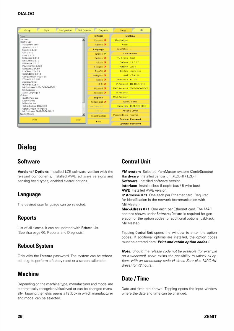
Dialog
Software
Versions / Options Installed LZE sotware version with the
relevant components, installed AWE sotware versions and
sensing head types, enabled clearer options.
Language
The desired user language can be selected.
Reports
List o all alarms. It can be updated with Refresh List.
(See also page 66, Reports and Diagnosis )
Reboot System
Only with the Foreman password. The system can be reboot-
ed, e. g. to perorm a actory reset or a screen calibration.
Machine
Depending on the machine type, manuacturer and model are
automatically recognized/displayed or can be changed manu-ally. Tapping the ields opens a list box in which manuacturer
and model can be selected.
Central Unit
YM system Selected YarnMaster system (Zenit/Spectra)
Hardware Installed central unit (LZE-II / LZE- III)
Software Installed sotware version
Interface Installed bus (Loepe bus / 5-wire bus)
AWE Installed AWE version
IP Adresse 0 / 1 One each per Ethernet card. Required
or identiication in the network (communication with
MillMaster)
Mac-Adress 0 / 1 One each per Ethernet card. The MAC
address shown under Software / Options is required or gen-
eration o the option codes or additional options (LabPack,
MillMaster).
Tapping Central Unit opens the window to enter the optioncodes. I additional options are installed, the option codes
must be entered here. Print and retain option codes !
Note: Should the release code not be available (for example
on a weekend), there exists the possibility to unlock all op-
tions with an emercency code (4 times Zero plus MAC-Ad-
dress) for 72 hours.
Date / Time
Date and time are shown. Tapping opens the input windowwhere the date and time can be changed.

7/16/2019 YM Zenit Manual-LZE 044843 003en
http://slidepdf.com/reader/full/ym-zenit-manual-lze-044843-003en 27/83
ZENIT 27
DIALOG
Access Level / Password
To prevent the modiication or deletion o data by unauthor-
ized persons, data inputs are protected with passwords.
I a menu item is tapped which is protected with a password,
the Access Level window is displayed. The required password
level is shown in Password Level.
Enter the new password (5 numbers max.) on the displayed
keyboard and conirm with OK.
The ollowing our password levels exist:
Display
Operator
Foreman
Service
Password Level Display : Most o the data and settings can
also be viewed and printed without password.
Changing the Password
During the startup, the oreman password is 1291, the opera-
tor password is 4711.
!It is recommended to change these passwords after
startup!
• Tap Foreman Password or Operator Password, respectively.
• Enter the new password on the displayed keyboard andconirm with OK.
• Conirm the changed password with Yes.

7/16/2019 YM Zenit Manual-LZE 044843 003en
http://slidepdf.com/reader/full/ym-zenit-manual-lze-044843-003en 28/83
28 ZENIT
CONFIGURATION
ConfigurationBasic system settings.
System
CheckLen Splice
Yarn length with which the splice check is perormed ater
a cut or ater a restart. The splice check length is automat-
ically set to 25 cm. It can be changed to a value between
0 and 120 cm.
Set CheckLenSplice to 0 cm to deactivate the splice check.
Total Spindles
Enter the number o installed spindles or this machine.
Headstock
Input o machine head location: Let or right.
Alarm Display
Selection o alarms to be displayed in a message box.
None No alarms are displayed
All All alarms are displayed
Technical Only the technical alarms are displayed:
System Alarm, Offline, etc.
Textile Only the “textile” alarms are displayed:
Off Count, Cluster, etc.
The respective error messages are displayed in the Dialog menu under Reports.
Yarn Count
The yarn numbering system (Nm, Nec, New, Tex, Den) is
selectable.
7/16/2019 YM Zenit Manual-LZE 044843 003en
http://slidepdf.com/reader/full/ym-zenit-manual-lze-044843-003en 29/83
ZENIT 29
CONFIGURATION
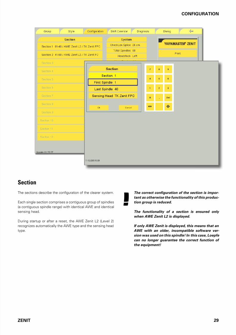
Section
The sections describe the coniguration o the clearer system.
Each single section comprises a contiguous group o spindles
(a contiguous spindle range) with identical AWE and identical
sensing head.
During startup or ater a reset, the AWE Zenit L2 (Level 2)
recognizes automatically the AWE type and the sensing head
type.
!The correct configuration of the section is impor-
tant as otherwise the functionality of this produc-
tion group is reduced.
The functionality of a section is ensured only
when AWE Zenit L2 is displayed.
If only AWE Zenit is displayed, this means that an
AWE with an older, incompatible software ver-
sion was used on this spindle! In this case, Loepfe can no longer guarantee the correct function of
the equipment!

7/16/2019 YM Zenit Manual-LZE 044843 003en
http://slidepdf.com/reader/full/ym-zenit-manual-lze-044843-003en 30/83
30 ZENIT
GROUP
Group
The working range or a maximum o 12 dierent lots can be
determined.
• Select the group.
• Enter the irst and the last spindle o the working range.
• Enter or change style and/or lot names via the alphanu-
meric keyboard.
• Save the input with the Assign command.
• Deine all other groups accordingly.
!To maintain the functionality of all sensing heads, a
group should not be created across section limits.
Note : Predefined clearer settings can be assigned to this
group in the Style menu.

7/16/2019 YM Zenit Manual-LZE 044843 003en
http://slidepdf.com/reader/full/ym-zenit-manual-lze-044843-003en 31/83
ZENIT 31
GROUP
Samples
T K Y M Z e n i t C
T K Y M Z
e n i t A / B
Sections Groups
Z e n i t C
Z e n i t F C
Z e n i t F P C
Z e n i t
Z e n i t F
Z e n i t F P
Section 1 01-60 / AWE Zenit L2 / TK Zenit FPC Group 1 01-60 / TK Zenit FPC (subdivision possible)
Section 1 01-60 / AWE Zenit L2 / TK Zenit FC Group 1 01-60 / TK Zenit FC (subdivision possible)
Section 1 01-60 / AWE ZenitL2 / TK Zenit C Group 1 01-60 / TK Zenit C (subdivision possible)
Section 1 01-40 / AWE Zenit L2 / TK Zenit FPC
Section 2 41–60 / AWE Zenit L2 / TK Zenit FC
Group 1 01-60 / TK Zenit FC
If a group is created over two sections with different sensing head
types, the functionality of the whole group is equivalent to the
lowest TK type. The complete working range looses the capability
to clear synthetic foreign matter (P).
Error message: “Reduced TK functionality! Functionality of whole
group reduced!”
To maintain the unctionality o all sensing heads, at least one
separate group per section must be created:
Group 1 01-40 / TK Zenit FPC (subdivision possible)
Group 2 41-60 / TK Zenit FC (subdivision possible)
Section 1 01-40 / AWE Zenit L2 / TK Zenit FC
Section 2 41-60 / AWE ZenitL2 / TK Zenit F
Group 1 01-60 / INVALID!!!
If a group is created over two sections with different sens-
ing head types (A (UR), B, or C), the functionality of this
group is not ensured!
Error message: “Incompatible TK!”
To maintain the unctionality o all sensing heads, at least one
separate group per section must be created:
Group 1 01-40 / TK Zenit FC (subdivision possible)
Group 2 41-60 / TK Zenit F (subdivision possible)
7/16/2019 YM Zenit Manual-LZE 044843 003en
http://slidepdf.com/reader/full/ym-zenit-manual-lze-044843-003en 32/83
32 ZENIT
STYLE
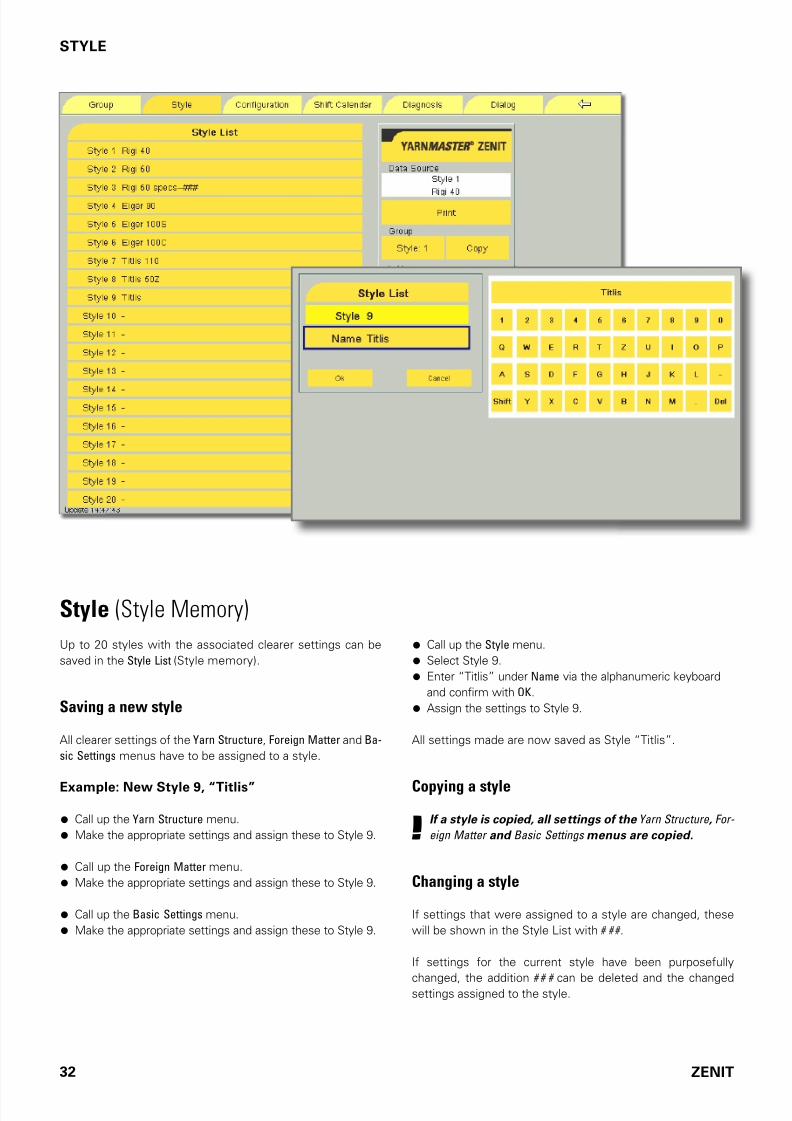
Style (Style Memory)
Up to 20 styles with the associated clearer settings can be
saved in the Style List (Style memory).
Saving a new style
All clearer settings o the Yarn Structure, Foreign Matter and Ba-
sic Settings menus have to be assigned to a style.
Example: New Style 9, “Titlis”
• Call up the Yarn Structure menu.
• Make the appropriate settings and assign these to Style 9.
• Call up the Foreign Matter menu.
• Make the appropriate settings and assign these to Style 9.
• Call up the Basic Settings menu.
• Make the appropriate settings and assign these to Style 9.
• Call up the Style menu.
• Select Style 9.
• Enter “Titlis” under Name via the alphanumeric keyboard
and conirm with OK.
• Assign the settings to Style 9.
All settings made are now saved as Style “Titlis”.
Copying a style
!If a style is copied, all settings of the Yarn Structure , For-
eign Matter and Basic Settings menus are copied.
Changing a style
I settings that were assigned to a style are changed, these
will be shown in the Style List with # # # .
I settings or the current style have been purposeully
changed, the addition # # # can be deleted and the changedsettings assigned to the style.
7/16/2019 YM Zenit Manual-LZE 044843 003en
http://slidepdf.com/reader/full/ym-zenit-manual-lze-044843-003en 33/83
ZENIT 33
STYLE
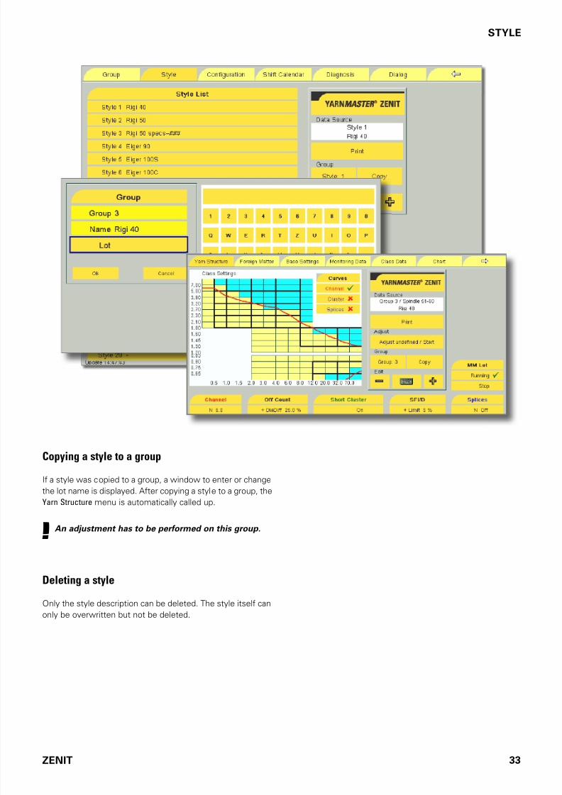
Copying a style to a group
I a style was copied to a group, a window to enter or change
the lot name is displayed. Ater copying a style to a group, the
Yarn Structure menu is automatically called up.
! An adjustment has to be performed on this group.
Deleting a style
Only the style description can be deleted. The style itsel can
only be overwritten but not be deleted.

7/16/2019 YM Zenit Manual-LZE 044843 003en
http://slidepdf.com/reader/full/ym-zenit-manual-lze-044843-003en 34/83
34 ZENIT
BASE SETTINGS
Base SettingsRepetitions
It must be deined how oten the exceeding o the limiting
value is tolerated (0 – 9).
Murata 21C In Off Count and Short Off Count, the maximum
number o repetitions (9) is automatically set and cannot be
changed. Cycle repetitions and alarms are processed by the
winding machine.
I the limiting value is exceeded, the spindle is blocked aterthe set number o repetitions.
The 7-Segment Display at the sensing head blinks con-
tinuously. The reason or spindle blocking is displayed on
the sensing head.
The spindel is in alarm. Reset spindle alarm: see page 69.
By the constant communication between the evaluation unit
computer and the spindle computer, the speciied ault length
(80 m max.) is drawn rom the cone.
NSLT Startup / F Startup / P Startup
With these settings, the bobbins with requent aults can be
detected. I requent startup cuts in the NSLT channel or or-
eign matter classes are registered, the spindle will be blocked
ater the number o repetitions set.

7/16/2019 YM Zenit Manual-LZE 044843 003en
http://slidepdf.com/reader/full/ym-zenit-manual-lze-044843-003en 35/83
ZENIT 35
BASE SETTINGS
Pilot Spindles
At a yarn change (Adjust) the yarn reerence value o the irst
80 m o yarn are measured and stored with the pilot spin-
dles. Each winding place o the group can be used as pilot
spindle.
Deine at least 10% o the spindles o every group as pilot
spindles. For groups o 10 spindles or less, select at least
two pilot spindles.
Data Acquisition
Mode
Last With the Last setting, the current data o a group or
spindle are indicated or the last 100 km, or example.
First With the First setting, the detection o monitor-
ing and classiication data o the current production is
stopped at e.g. 100 km Window Length (selectable). This
would mean or a group o 50 spindles that the irst 2 kmo every spindle are displayed together. With 1000 m/min
spindle speed, 100 km are reached in 2 min.
Cone With the Cone setting, the data o each individ-
ual cone will be shown in the Monitoring Data and Class
Data menus and automatically deleted ater changing.
The current data o the group are displayed or the last
e.g.100 km (Window Length).
Window Length
In Window Length, the observation length can be selectedbetween 10 –1000 km.
Reset Data
Under Reset Data the stored Monitoring Data and Class Data can
be erased. (The shit data are retained.)
• Activate Reset.
• Enter Yes in the message box “RESET Monitoring Data and
Class Data ?” .

7/16/2019 YM Zenit Manual-LZE 044843 003en
http://slidepdf.com/reader/full/ym-zenit-manual-lze-044843-003en 36/83
36 ZENIT
BASE SETTINGS
Fine Adjust
Mode
Single Ater a lot change, the yarn reerence value is
measured by a number o pilot spindles. Derived rom
this, the reerence value is ormed and sent to every
other spindle o the group. The individual average value
is then determined over approx. 24 km and adapted, i
required.
Continuous With Continuous Fine Adjust, the above pro-cedure is no longer completed. The measured yarn value
is continuously compared to the calculated mean value.
Non-textile changes, such as temperature, yarn tension,
humidity, etc. which influence the yarn diameter are being
compensated. Larger deviations rom the measured value
(even over a long period o time) trigger an alarm.
Diameter Base (Group)
Diameter
The determined diameter basis is shown ater an Adjust pro-
cess. This value is equivalent to the average yarn signal o
the group.
!This value should be changed by hand only in special
cases!
Fine Adjust Diff %
Deviation in percent o the yarn diameter averaged over all
spindles rom the basic value (adjustment value).
!A continuous deviation of this indication means a
yarn count deviation!

7/16/2019 YM Zenit Manual-LZE 044843 003en
http://slidepdf.com/reader/full/ym-zenit-manual-lze-044843-003en 37/83
ZENIT 37
BASE SETTINGS
Special FunctionsSplice Check ON / OFF
Switching the splice check on and o.
Note : If the Splice Check is switched off, the Splice menu area
in the Yarn Structure menu is disabled and the splice curve is
no longer displayed.
Reduction
Ater an initial start or adjust, many cuts can be registeredwith very sensitive settings in the yarn count channel or ault
cluster channel. To avoid these cuts, the sensitivity can be
reduced as required, i. e. the diameter limit value can be in-
creased by 0% to 250%.
The reduction is automatically canceled or every spindle a-
ter approx. 12 km o wound yarn.
The OFF setting switches o the yarn count channel as well as
the cluster channel during the irst approx. 12 km.
When an Spindle Adjust is perormed or a spindle, this change
o sensitivity also becomes active or approximately 12 km.
Reduction for a Cone Change
At a cone change, the limits or the long ault length (LL) and
the thin place length (-L) are set to 2 m. The diameter limits
or long aults (DL) and diameter decrease (-D) are less sensi-
tive according to the set reduction.
When the reduction is switched o, the long ault channel
as well as the thin place channel are switched o or the
irst 12 m.
Note : The yarn count channel and the foreign matter clearing are not active during the first 10 m after every cone change,
inde pendent of the set reduction.
F Sensor
The F-Sensor or this group can be switched o when oreign
matter clearing is not to be active on a group. The F-Mode
becomes inactive and the Foreign Matter menu as well as the
F-Clearing Data are no longer displayed.

7/16/2019 YM Zenit Manual-LZE 044843 003en
http://slidepdf.com/reader/full/ym-zenit-manual-lze-044843-003en 38/83
38 ZENIT
BASE SETTINGS
F Mode
The display area o the Foreign Matter Class window can be
selected:
Dark / Bright The “dark” and the “bright” area o the
class window will be displayed (classiication o all oreign
matter).
Dark The “dark” area o the class window will be dis-
played (classiication o dark oreign matter in the bright
yarn).
Cut Retries
I it is not possible to cut the thread, the spindle is blocked
ater the set number o cut repetitions. The maximum ault
length (80 m) is suctioned o the cone.
DFS Threshold / F Bright Var / F Dark Var
This inormation is to be used exclusively by service techni-cians or trained personnel.
Configuration Codes
!The configuration code may be changed only in
agreement with LOEPFE. The incorrect setting of
the configuration code can have serious conse-
quences for the clearer function!
Ater a actory reset or sotware update, the settings have to
be checked and possibly adapted to the old settings.
Note : It is recommended to copy to USB flash drive and ar-
chive all settings, before a factory reset or a software update!

7/16/2019 YM Zenit Manual-LZE 044843 003en
http://slidepdf.com/reader/full/ym-zenit-manual-lze-044843-003en 39/83
ZENIT 39
BASE SETTINGS
Test ModeYarnMaster Zenit has a test mode or
Cut Type
D Class Class cuts
F Class Foreign matter class cuts
Should a yarn ault be examined, select the corresponding cut
type or the corresponding number o the class ield ( D Class /
F Class).
I such a a ault is cut, the respective spindle remains idle. Re-
set o spindle blocking: see page 69.
On the following systems, the machines must also
be switched to test mode:
– M 21C – Espero i – Espero Nuovo – AC 238 – VJ Excello
Test Mode of Murata 21C Equipment:
• Set the VOS key switch to the «SET» position.
• Select menu F31 (YarnDectSampl)
• Make the appropriate choice and conirm with “Enter”
• Set the VOS key switch to the Monitor position.
• Conirm the question whether to save with key 1.
The setting is saved.
Proceed as ollows or the special cuts such as D Class/
F Class or P Cut:
• Select “more” and “0-Cut” and save.
• Remove the plastic cover and set the right switch
(SW5) to ON.

7/16/2019 YM Zenit Manual-LZE 044843 003en
http://slidepdf.com/reader/full/ym-zenit-manual-lze-044843-003en 40/83
40 ZENIT
BASE SETTINGS
D Class / F Class
Depending on the yarn ault to be examined, enter the num-
ber o the corresponding class as per below shown Number
Code tables.
7.0
5.0
3.9
3.2
2.7
2.3
2.1
1.8
1.60
1.45
1.30
1.20
0.83
0.80
0.75
0.65
0.5 1 1.5 2 3 4 6 8 12 20 32 70 cm
7
8
15 23
16
31
24
39
32
47
40
55
48
63
56
71
64
79
72
87
80
95
88
103
96
111
104
119
112
127
120
0
Number Code Table for D Class
0
7
8
15 23
16
31 39 47 55 63
71
64
79
72
87
80
95
88
103
96
111
104
119
112
127
120
24 32 40 48 56
9.0
6.0
4.0
3.0
2.0
1.5
1.0
0.7
0.5 1.0 1.5 2.0 3.0 4.0 8.0 cm
-9.0
-6.0
-4.0
-3.0
-2.0
-1.5
-1.0
-0.7
Class 110
Class 35
Number Code Table for F Class

7/16/2019 YM Zenit Manual-LZE 044843 003en
http://slidepdf.com/reader/full/ym-zenit-manual-lze-044843-003en 41/83
ZENIT 41
BASE SETTINGS
Display TK
It can be deined what the TK is to display ater a cut/spindle
start. (See also “7-Segment Display”, page 77)
Deault settings are marked with an asterisk (*).
!If required, these settings should be altered by in-
structed personnel only!
* Cut/Alarm Type
All textile yarn cuts and the corresponding cut alarms.
* Count Difference +/– 5%
A yarn diameter deviation o more than +/– 5% is displayed:
— Deviation smaller than +/– 5%
— Deviation more than – 5%
— Deviation more than + 5%
* Programstate Special
System Ino :
A Adjust is running
d Doing (cone change)
S Start signal standby (during Power On)
P Parameter standby (during StartUp)
* Technical Alarm
Alternating display o technical alarms :
A / 1 alternating Knie short-circuit
A / 3 alternating NTP signal line interruption
A / 4 alternating Knie blocking
A / 5 alternating Transer alarm

7/16/2019 YM Zenit Manual-LZE 044843 003en
http://slidepdf.com/reader/full/ym-zenit-manual-lze-044843-003en 42/83
42 ZENIT
YARN STRUCTURE
Yarn StructureDuring startup and lot change, the parameters or convention-
al clearing according to channels have to be set.
Channel
The settings o the clearer channels deine the limits or yarn
clearing (clearing curve):
N = Diameter limit or neps
DS = Diameter limit or short aultsLS = Limit or length o short aults
DL = Diameter limit or longs aults and double ends
LL = Limit or long aults length
-D = Limit o diameter reduction or thin places
-L = Limit or thin place length
All diameter limits are relative to the normal yarn diameter
(basis).
Clearing curve (red) The clearing curve is deined by the
settings o the dierent clearer channels. Yarn aults exceed-
ing this curve are cut.
Coarse Yarn Limitation
For coarse yarns, the Adjust process can determine a diame-
ter base larger than 868 mV. This has the eect that the com-
plete setting range (measuring range) is no longer available.
Accordingly, the diameter limit value or neps is automatical-
ly reduced or the channel settings and splice settings. The
changed settings are marked red and are shown in brackets.
The ollowing alarm message is displayed:
Coarse Yarn Limitation
Note: If the neps channel was switched off, it will be acti-
vated and set to the diameter limit value which was reduced
accordingly. If the yarn cannot be cleared in this manner, the neps channel has to be switched off manually.

7/16/2019 YM Zenit Manual-LZE 044843 003en
http://slidepdf.com/reader/full/ym-zenit-manual-lze-044843-003en 43/83
ZENIT 43
YARN STRUCTURE
Off Count
These settings make possible the detection o alse bobbins
or yarn with a larger o-count deviation.
+ DiaDiff / – DiaDiff
Depending on the quality or irregularity o the yarn, a dia-
meter deviation between ±3% and ±44% (dierence to ba-
sic value) can be selected. It can be set independently or the
positive as well as negative diameter deviation.
Coarse / Fine
According to the diameter deviation set, the yarn count devia-
tion is displayed or Coarse and Fine.
CntLen
The reerence length in which the average diameter dier-
ence is determined can be set between 10 and 50 m. This
allows or optimizing the detection o bobbin misplacementsand count variations.
+ Cuts /– Cuts
The number o cuts due to a positive or negative deviation o
the yarn diameter are listed separately.
This display makes possible the optimizing o the settings.
Short Off Count
CntLen
As opposed to the yarn count channel, the shorts count chan-
nel allows separate acquisition o yarn with a count devia-
tion over a length of less than 10 m. The reerence length
determining the average yarn count deviation can be set be-
tween 1 and 32 m.

7/16/2019 YM Zenit Manual-LZE 044843 003en
http://slidepdf.com/reader/full/ym-zenit-manual-lze-044843-003en 44/83
44 ZENIT
YARN STRUCTURE
Short/Long/Thin Cluster
These settings serve to detect clusters whose individual
aults are normally tolerated because they are outside o the
clearing curve. When these aults occur repeatedly over a
short distance, they can still have a negative eect.
To record periodic clusters, a deeper lying curve is deined
or the short, long and thin aults. Faults above or, on the thin
cluster, below these curves, are included in the cluster.
On / Off : The unction o the Short / Long / Thin Clusterchannels can be switched on or o. I a value is entered or
Observation Length and Fault, it is switched on. I OFF is select-
ed, it is switched o.
Yarn Count
Count
The wound yarn count is entered here as inormation. The
yarn numbering system (Nm, NeC, New, Tex, Den) can be
selected in the Configuration menu.
Act. DiaDiff
Indicates the eective diameter dierence o the yarn signal
o the spindle which started last rom the basis.

7/16/2019 YM Zenit Manual-LZE 044843 003en
http://slidepdf.com/reader/full/ym-zenit-manual-lze-044843-003en 45/83
ZENIT 45
YARN STRUCTURE
!
Faults / Observation Length
These two settings deine the limits o the accumulation den-
sity to the length unit or the aults which are above the clus-
ter curve.
When the set number o aults is exceeded within the set ob-
servation length, the spindle is blocked ater the set number
o repetitions.
Act. Faults
All events (irregularities) above the cluster curve are continu-
ously counted via the set Window Length (Base Settings menu).
The number obtained in this manner is converted to the ob-
servation length and displayed as setting suppor t in Act. Faults.
The set number of faults must be significantly
higher than the displayed events (Act. Faults).
If the number of counted events is 10% higher
than the set number of faults, cluster cuts can oc-
cur more frequently. (If necessary, increase the
«Diameter» value).
Diameter
Yarn diameter setting range:
Short (DS) 1.10 – 4.00
Long (DL) 1.04 – 2.00
Thin ( -D) - 6% – - 60%
The setting range reers to the normal yarn diameter. For ex-
ample, i the same setting is chosen as or the channel set-
ting (DS / DL / -D), it corresponds to the normal clearing curve
set. The number 1.0 would correspond to the base, viz. the
normal yarn diameter.
Length
Reerence length setting range:
Short (LS ) 1.0 cm – 10 cm
Long (LL) 6.0 cm – 200 cm
Thin (-L) 2.0 cm – 200 cm
7/16/2019 YM Zenit Manual-LZE 044843 003en
http://slidepdf.com/reader/full/ym-zenit-manual-lze-044843-003en 46/83
46 ZENIT
YARN STRUCTURE
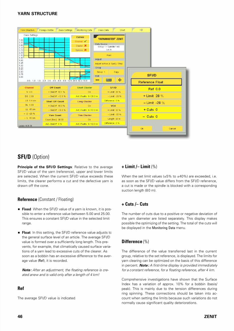
SFI/D (Option)
Principle of the SFI/D Settings: Relative to the average
SFI/D value o the yarn (reerence), upper and lower limits
are selected. When the current SFI/D value exceeds these
limits, the clearer perorms a cut and the deective yarn is
drawn o the cone.
Reference (Constant / Floating)
Fixed When the SFI/D value o a yarn is known, it is pos-
sible to enter a reerence value between 5.00 and 25.00.
This ensures a constant SFI/D value in the selected limit
range.
Float In this setting, the SFI/D reerence value adjusts tothe general surace level o an article. The average SFI/D
value is ormed over a sufciently long length. This pre-
vents, or example, that climatically caused surace varia-
tions o a yarn lead to excessive cuts o the clearer. As
soon as a bobbin has an excessive dierence to the aver-
age value (Ref), it is recorded.
Note : After an adjustment, the floating reference is cre-
ated anew and is valid only after a length of 4 km!
RefThe average SFI/D value is indicated.
+ Limit /– Limit (%)
When the set limit values (±5% to ±40%) are exceeded, i.e.
as soon as the SFI/D value diers rom the SFI/D reerence,
a cut is made or the spindle is blocked with a corresponding
suction length (80 m).
+ Cuts /– Cuts
The number o cuts due to a positive or negative deviation o
the yarn diameter are listed separately. This display makes
possible the optimizing o the setting. The total o the cuts will
be displayed in the Monitoring Data menu.
Difference (%)
The dierence o the value transerred last in the current
group, relative to the set reerence, is displayed. The limits or
yarn clearing can be optimized on the basis o this dierence
in percent. Note : A first-time display is provided immediately
for a constant reference, for a floating reference, after 4 km.
Comprehensive investigations have shown that the Surace
Index has a variation o approx. 10% or a bobbin (basis/
peak). This is mainly due to the tension dierences duringring spinning. These connections should be taken into ac-
count when setting the limits because such variations do not
normally cause signiicant quality deteriorations.

7/16/2019 YM Zenit Manual-LZE 044843 003en
http://slidepdf.com/reader/full/ym-zenit-manual-lze-044843-003en 47/83
ZENIT 47
YARN STRUCTURE
VCV (Option)
Variable CV Channel
The clearer calculates continuously the VCV values rom the
yarn pieces with the set check length and compares these
with its loating mean value.
Note : These values cannot be compared with the optical CV
values of the statistics or the data collected in the laboratory
because the check lengths as well as the cutting lengths for
calculation are different.
+ Limit /– Limit (%))
When the set limit values are exceeded (± 5% to ± 100%),i. e. as soon as the VCV value deviates accordingly rom the
mean value, a cut or a spindle blockage takes place with the
respective extraction length (1 to 50 m).
Length
The check length can be set between 1 m and 50 m.
+ Cuts /– Cuts
The number o cuts due to a positive or negative deviation o
the yarn diameter are listed separately.
Difference (%)
The deviation o the VCV value transmitted last in the current
group, relative to the mean value, is displayed. This allows or
optimizing the limit values.
Note : A first-time display of the deviation is performed after
4 km of wound yarn as from an adjustment.

7/16/2019 YM Zenit Manual-LZE 044843 003en
http://slidepdf.com/reader/full/ym-zenit-manual-lze-044843-003en 48/83
48 ZENIT
YARN STRUCTURE
Splice
The values set here are active during the irst 25 cm, i. e. in
the range where the splice runs through the sensing head.
The splice check length is automatically set to 25 cm. It can
be set in the range 0–120 cm as required. (See Configuration
menu.)
The splice check can be switched on and o in the Base Set-
tings menu.
UpY (Static Upper Yarn Detection)
In order to reliably detect a double-yarn o the cone, UpY must
not be set higher than 1.36 (36% diameter increase). This
setting should be checked and perhaps modiied at yarn ma-
terial change.
Coarse Yarn Limitation
See page 42.

7/16/2019 YM Zenit Manual-LZE 044843 003en
http://slidepdf.com/reader/full/ym-zenit-manual-lze-044843-003en 49/83
ZENIT 49
YARN STRUCTURE
MM Lot
These ields are active only when MillMaster is connected.
Running / Stop
Current status o the lot: Running
The data acquisition o the lot can be stopped with Stop.
The ollowing message box is shown:
“Stop production? Yes /No”
Production is manually stopped with Yes. MillMaster receives
a message and data acquisition is stopped or this lot (pro-
duction group).
Stopped / Start
Current status o the lot: Stopped
The data acquisition o the lot can be started with Start.
The ollowing message is shown:
“Start production? Yes/No”
Production is manually started with Yes. MillMaster receives
a message and data acquisition is started or this lot (produc-
tion group).
7/16/2019 YM Zenit Manual-LZE 044843 003en
http://slidepdf.com/reader/full/ym-zenit-manual-lze-044843-003en 50/83
50 ZENIT
YARN STRUCTURE
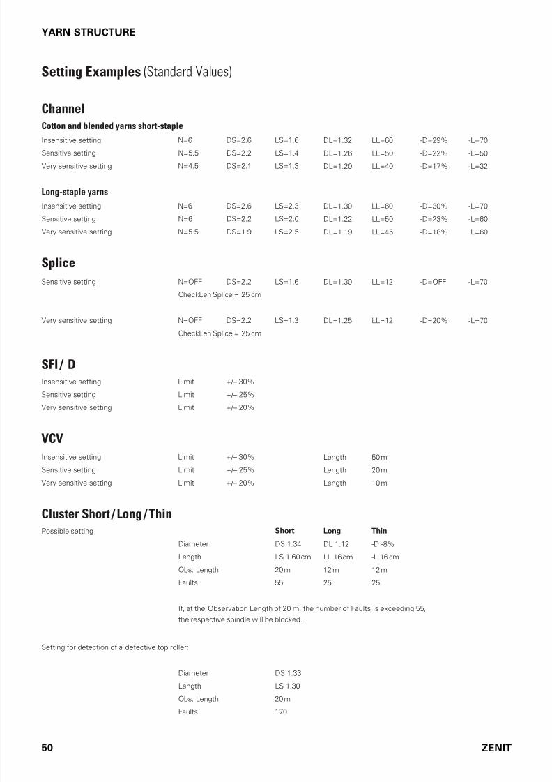
Setting Examples (Standard Values)
Channel
Cotton and blended yarns short-staple
Insensitive setting N=6 DS=2.6 LS=1.6 DL=1.32 LL=60 -D=29% -L=70
Sensitive setting N=5.5 DS=2.2 LS=1.4 DL=1.26 LL=50 -D=22% -L=50
Very sensitive setting N=4.5 DS=2.1 LS=1.3 DL=1.20 LL=40 -D=17% -L=32
Long-staple yarns
Insensitive setting N=6 DS=2.6 LS=2.3 DL=1.30 LL=60 -D=30% -L=70
Sensitive setting N=6 DS=2.2 LS=2.0 DL=1.22 LL=50 -D=23% -L=60
Very sensitive setting N=5.5 DS=1.9 LS=2.5 DL=1.19 LL=45 -D=18% -L=60
Splice
Sensitive setting N=OFF DS=2.2 LS=1.6 DL=1.30 LL=12 -D=OFF -L=70
CheckLen Splice = 25 cm
Very sensitive setting N=OFF DS=2.2 LS=1.3 DL=1.25 LL=12 -D=20% -L=70
CheckLen Splice = 25 cm
SFI / DInsensitive setting Limit +/– 30%
Sensitive setting Limit +/– 25%
Very sensitive setting Limit +/– 20%
VCV
Insensitive setting Limit +/– 30% Length 50 m
Sensitive setting Limit +/– 25% Length 20 m
Very sensitive setting Limit +/– 20% Length 10 m
Cluster Short / Long / ThinPossible setting Short Long Thin
Diameter DS 1.34 DL 1.12 -D -8%
Length LS 1.60 cm LL 16 cm -L 16 cm
Obs. Length 20 m 12 m 12 m
Faults 55 25 25
I, at the Observation Length o 20 m, the number o Faults is exceeding 55,
the respective spindle will be blocked.
Setting or detection o a deective top roller:
Diameter DS 1.33
Length LS 1.30
Obs. Length 20 m
Faults 170

7/16/2019 YM Zenit Manual-LZE 044843 003en
http://slidepdf.com/reader/full/ym-zenit-manual-lze-044843-003en 51/83
ZENIT 51
YARN STRUCTURE
Class Clearing
Clearing according to classes allows the creation o com-
pletely optional clearer characteristics. An advantage or an-
cy yarn, core-spun yarn etc.
The use o class clearing in combination with conventional
clearing oten achieves better results when short and long
aults occur at the same time.
Class Settings
Blue class fields = Class clearing is active
Yellow class fields = Class clearing is not active
The displayed clearing curve is deined by the settings o the
clearer channels. Yarn aults situated inside o this curve are
cut, while aults outside the curve remain in the yarn.
During clearing according to classes, speciic aults can also
be cut outside the clearing curve (select the desired ields).
Note: Class settings (blue) are not active during the splice
check.
Splice Class Settings
The splice class settings are active during each spindle start
or the irst 0–120 cm (CheckLen splice).
To show the Splice Class Settings window, Splices must be
activated.
Purple class fields = Splice class clearing is active
Yellow class fields = Splice class clearing is not active
The displayed splice curve is deined by the settings o the
splice channels. When clearing according to classes, the splic-
es are also cut in the activated class felds outside the clear-
ing curve.

7/16/2019 YM Zenit Manual-LZE 044843 003en
http://slidepdf.com/reader/full/ym-zenit-manual-lze-044843-003en 52/83
52 ZENIT
YARN STRUCTURE
Coarse Yarn Limitation
I a diameter base higher than 868 mV is determined during
adjustment, the class settings are tightened to the next class
below the coarse yarn boundary line, i required and i already
switched on. (Class Settings, Figure 1 and 2)
I the yarn cannot be cleared in this manner, the classes have
to be switched o completely in the respective area. (Marked
grey in Figure 3)
Figure 1
Figure 2
Figure 3

7/16/2019 YM Zenit Manual-LZE 044843 003en
http://slidepdf.com/reader/full/ym-zenit-manual-lze-044843-003en 53/83
ZENIT 53
FOREIGN MATTER
Foreign Matter (F)Foreign matter can be cleared only by classes.
The oreign matter detection requires the use o the sensing
heads TK YM ZENIT F or TK YM ZENIT FP
The display mode Dark or Dark/Bright can be selected in the
Base Settings menu.
Dark/Bright
Dark
F Class Settings
To speciy oreign matter clearing, the Normal mode must be
activated ().
Blue class fields = class clearing is active
7/16/2019 YM Zenit Manual-LZE 044843 003en
http://slidepdf.com/reader/full/ym-zenit-manual-lze-044843-003en 54/83
54
TITEL
ZENIT
FOREIGN MATTER
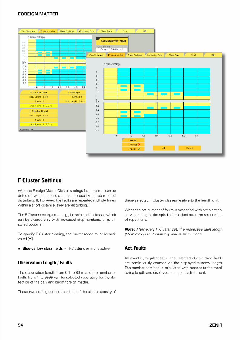
these selected F Cluster classes relative to the length unit.
When the set number o aults is exceeded within the set ob-
servation length, the spindle is blocked ater the set number
o repetitions.
Note : After every F Cluster cut, the respective fault length
(80 m max.) is automatically drawn off the cone.
Act. Faults
All events (irregularities) in the selected cluster class ields
are continuously counted via the displayed window length.
The number obtained is calculated with respect to the moni-
toring length and displayed to support adjustment.
F Cluster Settings
With the Foreign Matter Cluster settings ault clusters can be
detected which, as single aults, are usually not considered
disturbing. I, however, the aults are repeated multiple times
within a short distance, they are disturbing.
The F Cluster settings can, e. g., be selected in classes which
can be cleared only with increased step numbers, e. g. oil-
soiled bobbins.
To speciy F Cluster clearing, the Cluster mode must be acti-
vated ().
Blue-yellow class fields = F Cluster clearing is active
Observation Length / Faults
The observation length rom 0.1 to 80 m and the number o
aults rom 1 to 9999 can be selected separately or the de-
tection o the dark and bright oreign matter.
These two settings deine the limits o the cluster density o
7/16/2019 YM Zenit Manual-LZE 044843 003en
http://slidepdf.com/reader/full/ym-zenit-manual-lze-044843-003en 55/83
ZENIT 55
FOREIGN MATTER
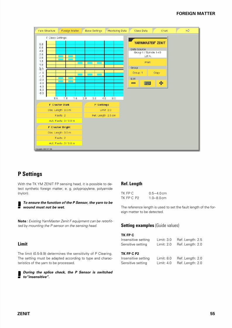
P Settings
With the TK YM ZENIT FP sensing head, it is possible to de-
tect synthetic oreign matter, e. g. polypropylene, polyamide
(nylon).
!To ensure the function of the P Sensor, the yarn to be
wound must not be wet.
Note : Existing YarnMaster Zenit F equipment can be retrofit-
ted by mounting the P sensor on the sensing head.
Limit
The limit (0.5-9.9) determines the sensitivity o P Clearing.
The setting must be adapted according to type and charac-
teristics o the yarn to be processed.
!During the splice check, the P Sensor is switched
to“insensitive”.
Ref. Length
TK FP C 0.5 – 4.0 cm
TK FP C P2 1.0– 8.0 cm
The reerence length is used to set the ault length o the or-
eign matter to be detected.
Setting examples (Guide values)
TK FP C
Insensitive setting Limit: 3.0 Re. Length: 2.5
Sensitive setting Limit: 2.0 Re. Length: 2.0
TK FP C P2
Insensitive setting Limit: 8.0 Re. Length: 2.0
Sensitive setting Limit: 4.0 Re. Length: 2.0

7/16/2019 YM Zenit Manual-LZE 044843 003en
http://slidepdf.com/reader/full/ym-zenit-manual-lze-044843-003en 56/83
56 ZENIT
MONITORING DATA
Monitoring DataCut Data
The total o all cut aults or events relative to the length dis-
played in Cut Declaration.
This data can be optionally viewed per spindle or group.
Note : When the sums of the Nep Cuts, Short Cuts, Long
Cuts and Thin Cuts are compared with Total Cuts in the corre-
sponding classification window, differences are possible be-
cause, depending on the setting, cuts can also be performed outside the displayed classes.
Cuts
Total Yarn Cuts Total o textile yarn aults
Short Off Count Cuts Yarn count deviation cuts in the short
count range
Off Count Cuts Yarn count deviation cuts
SFI/D Cuts Surace index cuts
F Cuts Foreign matter cuts
P Cuts Synthetic oreign matter cuts:PP, PE etc.)
Short Cluster Cuts Short ault cluster cuts
Long Cluster Cuts Long ault cluster cuts
Thin Cluster Cuts Thin place cluster cuts
F Cluster Cuts Foreign matter cluster cuts
VCV Cuts Cut resulting rom a deviation o the
VCV value rom the mean value
Bunch Cuts Cuts caused by bunches or similar
running aults
DBunch Cuts Delayed cuts caused by bunches or
similar running aults
Upper Yarn Cuts Cut caused by double yarn o thecone
Splices
Splice Cuts Cut splices
Splices Total o all wound splices
Splice Repetitions Caused by splice cuts, upper yarn
cuts, splices not completed
Alarms
Number o blockages ater exceeding the set number o rep-
etitions o the group or spindle.

7/16/2019 YM Zenit Manual-LZE 044843 003en
http://slidepdf.com/reader/full/ym-zenit-manual-lze-044843-003en 57/83
ZENIT 57
MONITORING DATA
Selection
Display mode can be selected.
Production
The data o the current production are displayed via the length
speciied in Cut Declaration (e. g. the last 1000 km).
Current Shift
Data o the current shit.
Previous shift
Data o the previous shit.
Cut Declaration
Mode
The data acquisition mode (Last, First, Cone) selected in the
Base Settings menu is displayed.
Length (Window Length)
The wound length to which the data reer is displayed.
Last Cut
In the classiication per spindle, the last cause o a cut or this
spindle is displayed.

7/16/2019 YM Zenit Manual-LZE 044843 003en
http://slidepdf.com/reader/full/ym-zenit-manual-lze-044843-003en 58/83
58 ZENIT
MONITORING DATA
Last Cut Display
Splice cut Channel Splice CH / N S L T (Neps, Short, Long, Thin)
Splice cut Class Splice CL / N S L T (Neps, Short, Long, Thin)
Channel cut Channel / N S L T (Neps, Short, Long, Thin)
Nonclassiied channel cut [Channel] / N S L T (Neps, Short, Long, Thin)
Class cut Class / N S L T (Neps, Short, Long, Thin)
Cut outside o indicated class ields (Class) / N S L T (Neps, Short, Long, Thin)
Foreign matter cut F / Dark, Bright
Foreign matter cut during splice check F Splice / Dark, Bright
Foreign matter cluster cut F Cluster / Dark, Bright
Foreign matter cut PP, PE etc. P
Short Cluster cut Cluster / S
Long Cluster cut Cluster / L
Thin Cluster cut Cluster / TSurace Index cut SFI/D / +, –
VCV cut VCV / +, –
O Count cut O Count / +, –
Short O Count cut Short Count / +, –
Base calibration cut Adjust
Upper Yarn cut Upper Yarn
Yarn bunch cut Bunch
Delayed yarn bunch cut DBunch
Machine cut Additional
Run-out with yarn ault Cut
Run-out without yarn ault No Cut
Drum wrap cut Drum WrapCut startup Startup
System, test button, beore Adjust System
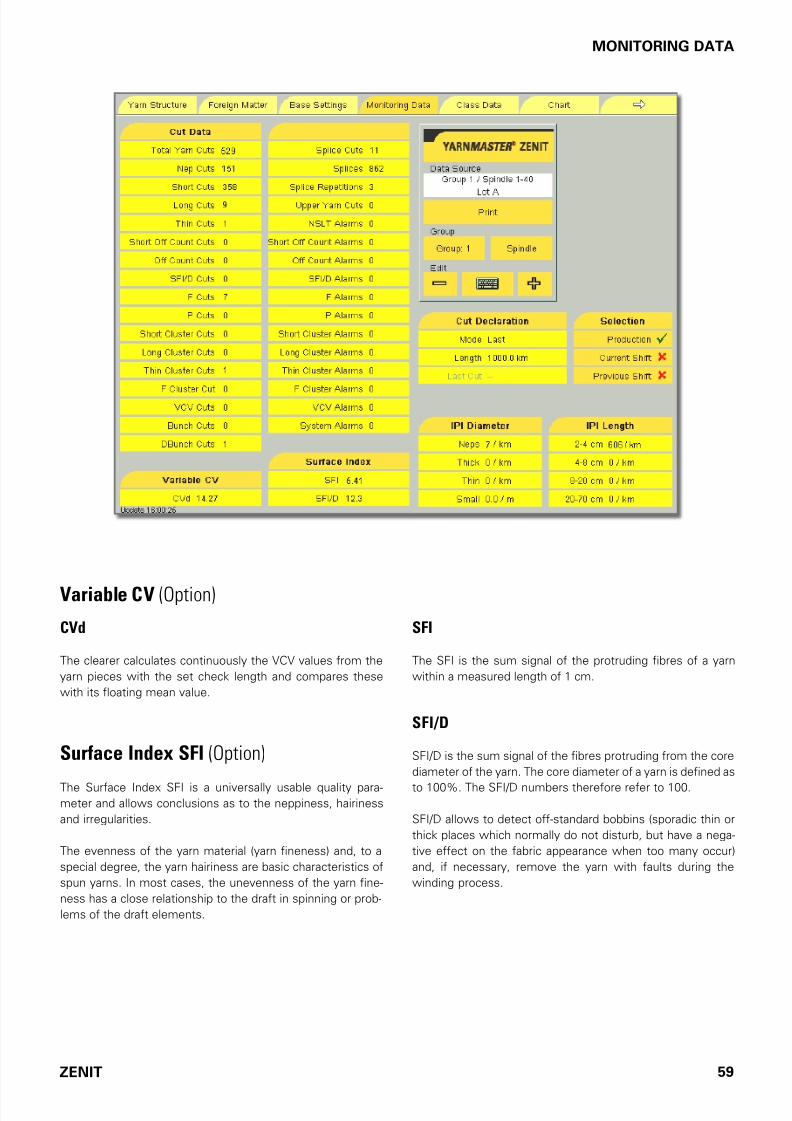
7/16/2019 YM Zenit Manual-LZE 044843 003en
http://slidepdf.com/reader/full/ym-zenit-manual-lze-044843-003en 59/83
ZENIT 59
MONITORING DATA
SFI
The SFI is the sum signal o the protruding ibres o a yarn
within a measured length o 1 cm.
SFI/D
SFI/D is the sum signal o the ibres protruding rom the core
diameter o the yarn. The core diameter o a yarn is deined as
to 100%. The SFI/D numbers thereore reer to 100.
SFI/D allows to detect o-standard bobbins (sporadic thin or
thick places which normally do not disturb, but have a nega-
tive eect on the abric appearance when too many occur)
and, i necessary, remove the yarn with aults during the
winding process.
Variable CV (Option)
CVd
The clearer calculates continuously the VCV values rom the
yarn pieces with the set check length and compares these
with its loating mean value.
Surface Index SFI (Option)
The Surace Index SFI is a universally usable quality para-meter and allows conclusions as to the neppiness, hairiness
and irregularities.
The evenness o the yarn material (yarn ineness) and, to a
special degree, the yarn hairiness are basic characteristics o
spun yarns. In most cases, the unevenness o the yarn ine-
ness has a close relationship to the drat in spinning or prob-
lems o the drat elements.

7/16/2019 YM Zenit Manual-LZE 044843 003en
http://slidepdf.com/reader/full/ym-zenit-manual-lze-044843-003en 60/83
60 ZENIT
MONITORING DATA
Imperfections IPI (Option)
The classical yarn clearing in the winding process is design-
ed or the recording o thick/thin places in the yarn which are
deined according to the respective ault classes.
In yarn ault classiication, seldom and requent yarn aults
are distinguished. The general rule is that the shorter the ault
length or the smaller the diameter variation, the more re-
quent the events. In textile usage, requent yarn aults are
also reerred to as Imperections.
The raw material, card wires, eccentric top rollers/bottom roll-ers, deective aprons, rings and ring travelers etc. have a sig-
niicant inluences on the Imperections.
The recording o the Imperections must be considered as de-
tailed online quality control in the winding process.
IPI Diameter
Diameter-related Imperections: In addition to the requent
yarn aults (Neps, Thicks, Thins), YarnMaster Zenit also clas-
siies the so-called very requent events (Small), the “small”
Imperections. These small Imperections are used to evalu-
ate the evenness o the checked yarn.
IPI Length
Length-related Imperections: In addition to the diameter-
related Imperections, length-related Imperections (rom
2–4 cm, 4–8 cm, 8–20 cm and 20–70 cm) are also classiied.

7/16/2019 YM Zenit Manual-LZE 044843 003en
http://slidepdf.com/reader/full/ym-zenit-manual-lze-044843-003en 61/83
ZENIT 61
CLASS DATA
Class Data Class Clearing Data
YarnMaster Zenit classiies all yarn aults in every group and
or every spindle. Faults o the yarn to be cleared are assigned
to certain ault classes based on the length and diameter.
Using this detailed inormation concerning the count as well
as length and thickness o the yarn aults, an optimum set-
ting o the clearer parameters can be perormed very ast and
eectively.
The numbers in the individual class ields indicate the cuts
and ault sums which remained in the yarn or the corre-
sponding classes relative to the wound length which is dis-
played on the screen.
Red numbers = Cut yarn aults
Black numbers = Yarn “aults” remaining in the yarn
Coarse yarn limitation I the coarse yarn limitation has
been activated, cuts and classiications above the coarse yarn
limitation are added to the respective classes below this line.
This data can be optionally viewed per spindle or group.
In case o classiication per spindle, the last cut ault is also
shown in its respective class ield. The exact cut position is
indicated (marked green). This indication is revised at the next
spindle stop.
Total Cuts displays the sum o the cut aults o the complete
class ields.
Note : Due to the completely independently operating soft- ware of the conventional clearing and the classification, it is
possible that faults which correspond to a short and a long
fault are displayed as cut below the clearer curve.
Mode
Coarse or ine classiication can be selected:
Coarse = Classiication data o the 23 main classes
Fine = Classiication data o all 128 classes
Selection / Cut Declaration
See Monitoring Data.
Classification per spindle

7/16/2019 YM Zenit Manual-LZE 044843 003en
http://slidepdf.com/reader/full/ym-zenit-manual-lze-044843-003en 62/83
62 ZENIT
CLASS DATA
F Clearing Data
YarnMaster Zenit F classiies all yarn aults in every group and
or every spindle.
No clearing data are displayed in class BS1. This is due to the
high sensitivity o this class.
Splice Classification Data
The classiication data are acquired in a special coarse clas-
siication raster optimized or splices.
For the irst 0 – 120 cm in which the splice runs through the
sensing head (splice check length), the splices are displayed
in the respective position.
The setting o the splice check length can be changed as re-
quired in the Configuration menu.
BS1

7/16/2019 YM Zenit Manual-LZE 044843 003en
http://slidepdf.com/reader/full/ym-zenit-manual-lze-044843-003en 63/83
ZENIT 63
CHART
ChartGraic representation o the cut data shown in the Data Item
List in orm o a bar chart.
Blue bars The values are scaled to the set Window Length.
Green bars The values are absolute or the length wound up
to then. Note : As long as the set length is not
reached by all spindles, of the group the cut num-
bers can still vary!
Red Line The red line shows the mean value o the cut da-
ta, calculated over the wound length.
Length Wound length (Window Length) in kilometers to
which the cut data reer.
Selection of Cut Data
Group / Machine With + or – the representation o an indi-
vidual group or an overview over the whole machine can be
selected.
Spindle I a single spindle is selected, it is marked red in thechart. Tapping the chart displays the cut data o this spindle.
Scale
Full Range Scale rom zero to the highest value o the dis-
played group.
Optimized Range (Spread) Scale rom the lowest to the
highest value o the displayed group. This representation is
used to make the delection better visible.
Relative Range Negative and positive deviations o the val-
ues o the spindles rom the mean value.
Percentage Negative and positive deviations o the spindles
rom the mean value in percent.
Values
The cut data o the spindles can be shown or hidden.
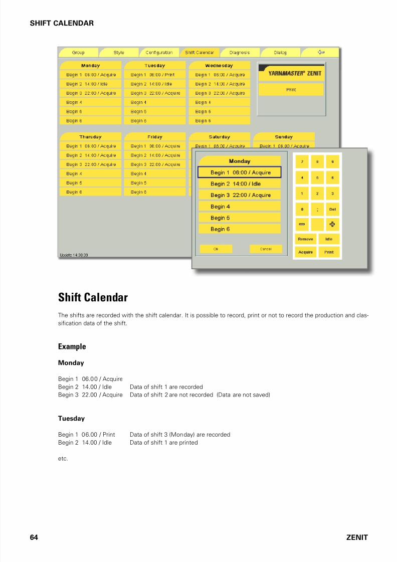
7/16/2019 YM Zenit Manual-LZE 044843 003en
http://slidepdf.com/reader/full/ym-zenit-manual-lze-044843-003en 64/83
64 ZENIT
SHIFT CALENDAR
Shift CalendarThe shits are recorded with the shit calendar. It is possible to record, print or not to record the production and clas-
siication data o the shit.
Example
Monday
Begin 1 06.00 / Acquire
Begin 2 14.00 / Idle Data o shit 1 are recorded
Begin 3 22.00 / Acquire Data o shit 2 are not recorded (Data are not saved)
Tuesday
Begin 1 06.00 / Print Data o shit 3 (Monday) are recorded
Begin 2 14.00 / Idle Data o shit 1 are printed
etc.
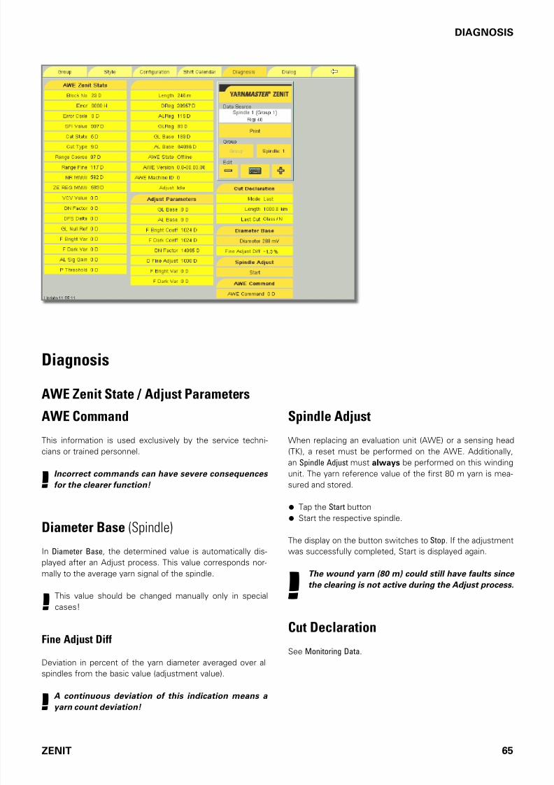
7/16/2019 YM Zenit Manual-LZE 044843 003en
http://slidepdf.com/reader/full/ym-zenit-manual-lze-044843-003en 65/83
ZENIT 65
DIAGNOSIS
Diagnosis
AWE Zenit State / Adjust Parameters
AWE Command
This inormation is used exclusively by the service techni-
cians or trained personnel.
!Incorrect commands can have severe consequences
for the clearer function!
Diameter Base (Spindle)
In Diameter Base, the determined value is automatically dis-played ater an Adjust process. This value corresponds nor-
mally to the average yarn signal o the spindle.
!This value should be changed manually only in special
cases!
Fine Adjust Diff
Deviation in percent o the yarn diameter averaged over all
spindles rom the basic value (adjustment value).
!A continuous deviation of this indication means a
yarn count deviation!
Spindle Adjust
When replacing an evaluation unit (AWE) or a sensing head
(TK), a reset must be perormed on the AWE. Additionally,
an Spindle Adjust must always be perormed on this winding
unit. The yarn reerence value o the irst 80 m yarn is mea-
sured and stored.
• Tap the Start button
• Start the respective spindle.
The display on the button switches to Stop. I the adjustment
was successully completed, Start is displayed again.
!The wound yarn (80 m) could still have faults since
the clearing is not active during the Adjust process.
Cut Declaration
See Monitoring Data.

7/16/2019 YM Zenit Manual-LZE 044843 003en
http://slidepdf.com/reader/full/ym-zenit-manual-lze-044843-003en 66/83
66 ZENIT
REPORTS AND DIAGNOSIS
Reports and Diagnosis
Depending on the setting in the Configuration menu, the textile, the technical, all or or none alarms are displayed with a message
box on the screen.
Hide The alarm message is hidden.
Previous The previous alarm message is displayed.
Clear The displayed alarm message is deleted
The list o all alarm messages is displayed in the Dialog menu.
Textile Alarms
Message Explanation / Cause Action
OffCnt Alarm
ShortCnt Alarm
Yarn count o-limit.
Set diameter deviation exceeded.
Remove bobbin.
Reset spindle alarm and restart spindle.
Faulty yarn is automatically removed rom
the cone (max. 80 m).
NSLT Alarm Yarn ault alarm.
Preselected number o yarn count startup cuts is
exceeded.
Remove bobbin.
Reset spindle alarm and restart spindle.
Faulty yarn is automatically removed rom
the cone.
Cluster S Alarm
Cluster L Alarm
Cluster T Alarm
Fault cluster alarm.
Excessive ault accumulation.
Set number o aults exceeded.
Remove bobbin.
Reset spindle alarm and restart spindle.
Faulty yarn is automatically removed rom
the cone (max. 80 m).
F Alarm Foreign matter alarm.
Preselected number o oreign matter startup cuts
is exceeded.
Clean optics.
Remove bobbin.
Reset spindle alarm and restart spindle.
F Cluster Alarm Foreign matter cluster alarm.
Preselected number o oreign matter cluster deects
is exceeded.
Remove bobbin.
Reset spindle alarm and restart spindle.
Faulty yarn is automatically removed rom
the cone (max. 80 m).
P Alarm Foreign matter alarm or synthetic ibers PP, PE, etc.Preselected number o PP / PE oreign matter cuts
during start-up is exceeded.
Clean sensor.Remove bobbin.
Reset spindle alarm and restart spindle.
SFI/D Alarm Surace Index alarm.
Preselected number o SFI/D cuts is exceeded.
Remove bobbin.
Reset spindle alarm and restart spindle.
Faulty yarn is automatically removed rom
the cone (max. 80 m).
VCV Alarm Deviation rom determined VCV value.
Preselected number o VCV cuts is exceeded
Remove bobbin.
Reset spindle alarm and restart spindle.
Faulty yarn is automatically removed rom
the cone (max. 50 m).
! Schlafhorst AC 238/146: In addition remove fault manually from the cone!
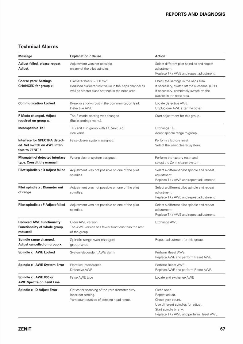
7/16/2019 YM Zenit Manual-LZE 044843 003en
http://slidepdf.com/reader/full/ym-zenit-manual-lze-044843-003en 67/83
ZENIT 67
REPORTS AND DIAGNOSIS
Technical Alarms
Message Explanation / Cause Action
Adjust failed, please repeat
Adjust.
Adjustment was not possible
on any o the pilot spindles.
Select dierent pilot spindles and repeat
adjustment.
Replace TK / AWE and repeat adjustment.
Coarse yarn: Settings
CHANGED for group x!
Diameter basis > 868 mV
Reduced diameter limit value in the neps channel as
well as stricter class settings in the neps area.
Check the settings in the neps area.
I necessary, switch o the N channel (OFF).
I necessary, completely switch o the
classes in the neps area.
Communication Locked Break or short-circuit in the communication lead.
Deective AWE.
Locate deective AWE:
Unplug one AWE ater the other.
F Mode changed, Adjust
required on group x.
The F mode setting was changed
(Basic settings menu).
Start adjustment or this group.
Incompatible TK! TK Zenit C in group with TK Zenit B or
vice versa.
Exchange TK.
Adapt spindle range to group.
Interface for SPECTRA detect-
ed. Set switch on AWE Inter-
face to ZENIT !
False clearer system assigned. Perorm a actory reset
Select the Zenit clearer system.
Mismatch of detected interface
type. Consult the manual!
Wrong clearer system assigned. Perorm the actory reset and
select the Zenit clearer system.
Pilot spindle x : D Adjust failed Adjustment was not possible on one o the pilot
spindles.
Select a dierent pilot spindle and repeat
adjustment.
Replace TK / AWE and repeat adjustment.
Pilot spindle x : Diameter out
of range
Adjustment was not possible on one o the pilot
spindles.
Select a dierent pilot spindle and repeat
adjustment.
Replace TK / AWE and repeat adjustment.
Pilot spindle x : F Adjust failed Adjustment was not possible on one o the pilot
spindles.
Select a dierent pilot spindle and repeat
adjustment.
Replace TK / AWE and repeat adjustment.
Reduced AWE functionality!
Functionality of whole group
reduced!
Older AWE version.
The AWE version has ewer unctions than the rest
o the group.
Exchange AWE.
Spindle range changed,Adjust cancelled on group x.
Spindle range was changedgroup-wide.
Repeat adjustment or this group.
Spindle x : AWE Locked System-dependent AWE alarm Perorm Reset AWE.
Replace AWE and perorm Reset AWE.
Spindle x : AWE System Error Electrical intererence
Deective AWE
Perorm Reset AWE.
Replace AWE and perorm Reset AWE.
Spindle x : AWE 800 or
AWE Spectra on Zenit Line
False AWE type Locate and exchange AWE
Spindle x : D Adjust Error Optics or scanning o the yarn diameter dirty.
Incorrect zeroing.
Yarn count outside o sensing head range.
Clean optic.
Repeat adjust.
Check yarn count.
Use dierent spindles or adjust.
Start spindle briely.
Replace TK / AWE and perorm Reset AWE.

7/16/2019 YM Zenit Manual-LZE 044843 003en
http://slidepdf.com/reader/full/ym-zenit-manual-lze-044843-003en 68/83
68 ZENIT
REPORTS AND DIAGNOSIS
Message Explanation / Cause Action
Spindle x : D Sensing Light
out of Range
Light sensor or scanning the yarn diameter
out o tolerance.Optic dirty.
TK deective.
Clean optic.
Start spindle briely.Replace TK, and perorm Reset AWE.
Replace AWE and perorm Reset AWE.
Spindle x : F Adjust Error Optical system or oreign matter detection dirty.
Yarn count or yarn color outside o sensing head range.
Large number o oreign ibers succeeding one another.
Clean optic.
Repeat adjust.
Check yarn count or color respectively.
Change bobbins.
Use dierent spindle or Adjust.
Spindle x : F Sensing Light
out of Range
Light sensor or oreign matter detection
out o tolerance.
Optic dirty.
Incorrect setting.TK deective.
Clean optic.
Start spindle briely.
Replace TK, and perorm Reset AWE.
Replace AWE and perorm Reset AWE.
Spindle x : Group number: ??? AWE which is not assigned to a group.
Assignment o group number lacking.
Assign all spindles to group.
Spindle x : Incompatible AWE
software version
AWE reports a wrong sotware version. Install correct AWE sotware
Exchange AWE and perorm Reset AWE.
Spindle x : Invalid AWE Ma-
chine Type
AWE reports a wrong machine type,
i. e. the wrong AWE sotware was loaded.
Check AWE sotware.
Import correct AWE sotware.
Exchange AWE and perorm Reset AWE.
Spindle x : No Sensing Head No TK connected. Insert TK.
Check connector.
Spindle x : No Speed Informa-
tion
Drum signals lacking.
Cable break.
Sensor or spindle computer deective.
Start spindle briely.
Replace AWE and perorm Reset AWE.
Exchange sensor or spindle computer.
Spindle x : No Yarn Break Knie locked through iber accumulation.
Knie dull.
Sensing head coil ruptured.
Knie power supply lacking.
Clean TK.
Exchange knie.
Check knie power supply.
Replace TK / AWE and perorm Reset AWE.
Spindle x : Reduced TK func-
tionality! Functionality of
whole group reduced!
The TK version has ewer unctions than the rest
o the production group.
Exchange TK.
Adapt the spindle range o the group.
Spindle x : System Alarm System error.
Electrical intererence.
Deective AWE.
Perorm Reset AWE.
Replace AWE and perorm Reset AWE.
Spindle x : Locked System-dependent AWE alarm. Perorm Reset AWE.
Replace AWE and perorm Reset AWE.
Spindle x: Offline No communication.
AWE does not communicate with ZE.
Perorm Reset AWE.
Replace AWE and perorm Reset AWE.
Startup Adjust for Group x New unit sotware was installed.
An adjustment was perormed during the start
on each spindle.
None

7/16/2019 YM Zenit Manual-LZE 044843 003en
http://slidepdf.com/reader/full/ym-zenit-manual-lze-044843-003en 69/83
ZENIT 69
REPORTS AND DIAGNOSIS
Spindle Blocking - Display / Reset
Machine Type Display on Winding Unit Reset
Murata 21C Start switch is lit in yellow To start spindle: Turn the Start switch by 180 degrees
Orion
Polar
Smaro
Spindle is lit in red (red light blinks) Alarm reset: Push black button
To start spindle: Push white button
Espero i
VJ Excello
Espero Nuovo
Spero
Spindle is lit in red (red light blinks) Alarm reset: Push red button
To start spindle: Push green button
EJP 438
DTM 439
Spindle is lit in red and yellow (textile alarms)
Red light blinks (technical alarms)
Alarm reset: Push on red light
The bobbin is ejected, the ault length is suctioned o
and winding continues automatically (textile alarms)
AC 238 / 146 Spindle is lit in red and yellow (textile alarms)Red light blinks (technical alarms)
Alarm reset: Perorm TK resetTo start spindle: Turn switch
AC 238 / 147 Spindle is lit in red and yellow (textile alarms)
Red light blinks (technical alarms)
Alarm reset: Push on red/yellow light
The bobbin is ejected, the ault length is suctionned o
and winding continues automatically (textile alarms)

7/16/2019 YM Zenit Manual-LZE 044843 003en
http://slidepdf.com/reader/full/ym-zenit-manual-lze-044843-003en 70/83
70 ZENIT
CHECKS AND MAINTENANCE
Checks and Maintenance
General
The yarn clearing YarnMaster Zenit installation requires hardly
any maintenance. Regular checks o the yarn clearing installa-
tion are vital, not only to examine the correct settings but also
to assure its proper unction.
Moreover, it is recommended to have a yearly clearer check
carried out by an authorized Service Station.
!Maintenance works must be made by trained and au-
thorized personnel only !
DailyCentral Unit LZE
• Check the desired settings.
Checking the Adjust value.
When the setting is correct, the Act.DiaDiff setting (Yarn
Structure menu) should not be greater than 10% ater ev-
ery spindle stop.
• Select Reports in Dialog menu.
Yarn-caused spindle blockages as well as events caused
by process and system are displayed. (See table Reports
and Diagnosis)
Sensing Heads TK
• Check the 7-Segment Display. When the base is set cor-
rectly, the horizontal bar must be in the middle while the
yarn is running. Bar at the top or bottom indicates yarn di-
ameter deviations o more than +/- 5%.
Weekly
Sensing Heads TK
Knife (Cut control)
• Initiate a cut at each sensing head with the Test button.
• The knie should react and be able to cut a double end.
• Ater each cut, the knie must return to its initial position.
• I the plastic part remains visible, open the housing and
clean the cutting device.
• I necessary, replace the knie according to the illustration.
!The knife must be inserted the other way round on
Espero i, Espero Nuovo and Excello sensing heads!
Yarn Guide
To ensure that the yarn aults are detected, the thread must
run at the bottom o both yarn guides.
• Check the yarn guides or deects (cracks, indentations by
thread).
• I necessary, replace the thread guide in the yarn guideplate (igure 1) or the sensing head cover with the perma-
nently mounted yarn guide plate (igure 2).
T10
T8 T10
Figure 1 Figure 2
T8
T10
T10
Yarn guide Plate
Thread guide
Cover
Yarnguide plate

7/16/2019 YM Zenit Manual-LZE 044843 003en
http://slidepdf.com/reader/full/ym-zenit-manual-lze-044843-003en 71/83
ZENIT 71
CHECKS AND MAINTENANCE
Cleaning the Optics
In cases o substantial dirt accumulation, the cleaning o the
optic ield by means o cotton swabs is recommended.
!Under no circumstances should hard/sharp objects
be used for cleaning! Risk of damage!
!
If marking paint, Paraffin or antistatic oils are used,
the optics must be cleaned in shorter intervals.
Light soiling such as dust can be removed using our proven
TK-Clean (Part No. 014359.900 ) cleaning agent.
Heavy soiling ( i. e. wax residue) can be removed using one o
the ollowing agents:
“Zippo Premium Lighter Fluid” lighter luid
“Ronsonol Lighter Fluid” lighter luid
Medical grade benzene (Do not use benzene, see Prohi-
bited Solvents!)
n-Heptane (C7
H16
)
Cypar7, Cycloaliphat (C7), a SHELL product
Note : These solvents are highly inflammable, hazardous
goods and excluded from normal air and surface trans porta-
tion. For this reason, they have to be procured locally. As a re-
sult of their world-wide availability and good cleaning effect,
we recommend the use of lighter fluids.
Forbidden Substances
!Loepfe strictly declines any responsibility for dam-
age claims resulting from the use of un suitable
cleaning substances!
The substances listed below must be avoided by all means,
as their use will destroy the optical system:
Aromatic hydrocarbons, e.g. benzene, benzole, toluol
All kinds o alcohol, e.g. methanol, ethanol
Spirit
Acetone
Automobile and aviation gasoline
Replacement of AWE or Sensing Head
When replacing an AWE or a sensing head, it must
be ensured that an identical AWE or an identical
sensing head is used! Do not mix different Zenit
versions within one machine! The functionality
of the equipment is not guaranteed when differ-
ent versions (A(UR), B or C) are used within a ma-
chine/group!
A alse AWE or TK version causes the display o an error
message.
When replacing the AWE or a sensing head, a reset must be
perormed on the AWE. Press the test button on the sensing
head or ive seconds = Reset AWE.
Additionally, a Spindle Adjust must always be perormed on
this winding unit. (See the Diagnosis menu.)
!The wound yarn (80 m) could still have faults since
the clearing is not active during the Adjust process.
I unjustifed yarn count or cluster alarms are determined a-
ter a Spindle Adjust, the reduction has to be increased in the
Base Settings menu.
!
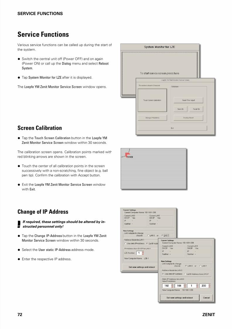
7/16/2019 YM Zenit Manual-LZE 044843 003en
http://slidepdf.com/reader/full/ym-zenit-manual-lze-044843-003en 72/83
72 ZENIT
SERVICE FUNCTIONS
Change of IP Address
!If required, these settings should be altered by in-
structed personnel only!
• Tap the Change IP-Address button in the Loepfe YM Zenit
Monitor Service Screen window within 30 seconds.
• Select the User static IP-Address address mode.
• Enter the respective IP address.
Screen Calibration
• Tap the Touch Screen Calibration button in the Loepfe YM
Zenit Monitor Service Screen window within 30 seconds.
The calibration screen opens. Calibration points marked with
red blinking arrows are shown in the screen.
• Touch the center o all calibration points in the screen
successively with a non-scratching, ine object (e.g. ball
pen tip). Conirm the calibration with Accept button.
• Exit the Loepfe YM Zenit Monitor Service Screen window
with Exit.
Service Functions
Various service unctions can be called up during the start o
the system.
• Switch the central unit o (Power OFF) and on again
(Power ON) or call up the Dialog menu and select Reboot
System.
• Tap System Monitor for LZE ater it is displayed.
The Loepfe YM Zenit Monitor Service Screen window opens.

7/16/2019 YM Zenit Manual-LZE 044843 003en
http://slidepdf.com/reader/full/ym-zenit-manual-lze-044843-003en 73/83
ZENIT 73
SERVICE FUNCTIONS
Factory Reset
!A factory reset deletes all settings and data, they have
to be entered again.
!It is recommended to copy to USB flash drive and
archive all settings and, if required, the data for all
groups, before a factory reset!
• Tap the Factory Reset button in the Loepfe YM Zenit Monitor
Service Screen window and continue with Yes.
The actory reset is perormed.
• Exit the Loepfe YM Zenit Monitor Service Screen window
with Exit.
• Previous to the factory reset assure that the switch at
the AWE interface is at position “AWE ZENIT” .
The Select YM-System dialog ield opens.
• Select “Zenit” and conirm with OK.
Reset of Fine Adjust Values
I required, all ine adjust values on all AWEs can be reset:
• Tap the Reset Fine Adjust button in the Loepfe YM Zenit
Monitor Service Screen window and continue with Yes.
The ine adjust values are reset.
• Exit the Loepfe YM Zenit Monitor Service Screen window
with Exit.
Ater a Reset Fine Adjust, the ine adjust values are automati-
cally determined again.
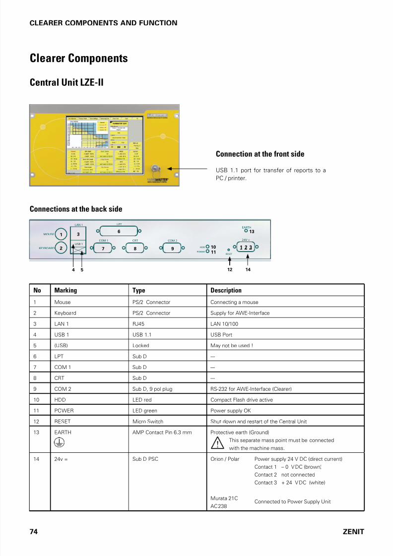
7/16/2019 YM Zenit Manual-LZE 044843 003en
http://slidepdf.com/reader/full/ym-zenit-manual-lze-044843-003en 74/83
74 ZENIT
SERVICE FUNCTIONSCLEARER COMPONENTS AND FUNCTION
Clearer Components
Central Unit LZE-II
Connection at the front side
USB 1.1 port or transer o reports to a
PC / printer.
Connections at the back side
24V =COM 2CRTCOM 1
LPT
USB 1
KEYBOARD
MOUSE
HDD
POWER
RESET
LAN 1EARTH
2
3
4
6
7
5
8 9 1011
14
13
12
1 2 3
1
No Marking Type Description1 Mouse PS/2 Connector Connecting a mouse
2 Keyboard PS/2 Connector Supply or AWE-Interace
3 LAN 1 RJ45 LAN 10/100
4 USB 1 USB 1.1 USB Port
5 (USB) Locked May not be used !
6 LPT Sub D ---
7 COM 1 Sub D ---
8 CRT Sub D ---
9 COM 2 Sub D, 9 pol plug RS-232 or AWE-Interace (Clearer)
10 HDD LED red Compact Flash drive active
11 POWER LED green Power supply OK
12 RESET Micro Switch Shut down and restart o the Central Unit
13 EARTH AMP Contact Pin 6.3 mm Protective earth (Ground)
This separate mass point must be connected
with the machine mass.
14 24v = Sub D PSC Orion / Polar Power supply 24 V DC (direct current)
Contact 1 – 0 V DC (brown)
Contact 2 not connected
Contact 3 + 24 V DC (white)
Murata 21C
AC 238Connected to Power Supply Unit
!

7/16/2019 YM Zenit Manual-LZE 044843 003en
http://slidepdf.com/reader/full/ym-zenit-manual-lze-044843-003en 75/83
ZENIT 75
SERVICE FUNCTIONSCLEARER COMPONENTS AND FUNCTION
Central Unit LZE-III
Connection at the front side
USB 2.0 port or transer o reports to a PC / printer.
Connections at the back side
The LZE-III has an internal uninterruptible power supply (UPS). Write operations in progress to the Compact Flash board are
terminated normally and no new write operations begun during interruption. The buer capacity o the UPS is suicient to op-
erate the LZE-III or a maximum o 5 seconds with the monitor switched o. During current interruption, the monitor and theUSB port are switched o. Touchscreen entries are not possible during this time. Central unit LZE-III starts normally when the
regular power supply is available again.
Marking Type Description
LAN 0 / LAN 1 RJ45 LAN 10 / 100 / 1000
USB 0 / USB 1 USB 2.0 USB Port
LOEPFE 1 Sub-D, 9 pol plug 2/5-wire-bus
HDD LED red Compact Flash drive active
PWR LED green / red Power supply OK
Reset Micro Switch Automatic restart o central unit.
Caution: Saved data will be lost!
AMP Contact Pin 6.3 mm PE Protective Earth (Ground)
This separate mass point must be connected
with the machine mass.
Power Sub D PSC Orion / Polar Power supply 24 V DC (direct current)
Contact 1 – 0 V DC (brown)
Contact 2 not connected
Contact 3 + 24 V DC (white)
M21C / Espero i
Espero Nuovo
Smaro / Spero
AC 238 / EJP 438
DTM 439 / VJ Excello Connected to Power Supply Unit
(Power ON/OFF) Micro Switch Shut down to standby mode (5V) and restart o central unit.
!
!
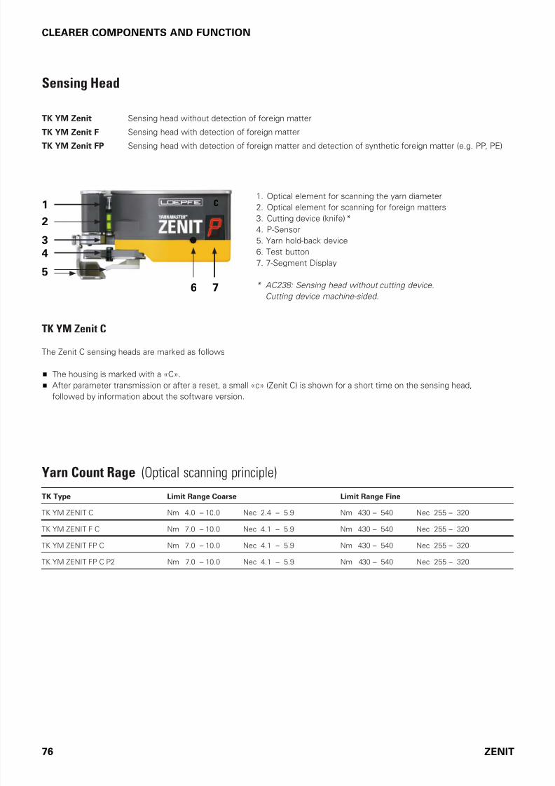
7/16/2019 YM Zenit Manual-LZE 044843 003en
http://slidepdf.com/reader/full/ym-zenit-manual-lze-044843-003en 76/83
76 ZENIT
SERVICE FUNCTIONSCLEARER COMPONENTS AND FUNCTION
C1
2
6 7
3
5
4
Sensing Head
TK YM Zenit Sensing head without detection o oreign matter
TK YM Zenit F Sensing head with detection o oreign matter
TK YM Zenit FP Sensing head with detection o oreign matter and detection o synthetic oreign matter (e.g. PP, PE)
1. Optical element or scanning the yarn diameter
2. Optical element or scanning or oreign matters
3. Cutting device (knie) *
4. P-Sensor
5. Yarn hold-back device
6. Test button
7. 7-Segment Display
* AC238: Sensing head without cutting device.
Cutting device machine-sided.
TK Type Limit Range Coarse Limit Range Fine
TK YM ZENIT C Nm 4.0 – 10.0 Nec 2.4 – 5.9 Nm 430 – 540 Nec 255 – 320
TK YM ZENIT F C Nm 7.0 – 10.0 Nec 4.1 – 5.9 Nm 430 – 540 Nec 255 – 320
TK YM ZENIT FP C Nm 7.0 – 10.0 Nec 4.1 – 5.9 Nm 430 – 540 Nec 255 – 320
TK YM ZENIT FP C P2 Nm 7.0 – 10.0 Nec 4.1 – 5.9 Nm 430 – 540 Nec 255 – 320
TK YM Zenit C
The Zenit C sensing heads are marked as ollows
The housing is marked with a «C».
Ater parameter transmission or ater a reset, a small «c» (Zenit C) is shown or a short time on the sensing head,
ollowed by inormation about the sotware version.
Yarn Count Rage (Optical scanning principle)

7/16/2019 YM Zenit Manual-LZE 044843 003en
http://slidepdf.com/reader/full/ym-zenit-manual-lze-044843-003en 77/83
ZENIT 77
SERVICE FUNCTIONSCLEARER COMPONENTS AND FUNCTION
Mounting of P-Sensors
Existing YarnMaster Zenit F equipment can be retroitted by
mounting the P-Sensor onto the sensing head.
With P-Sensor Without P-Sensor
Sensing Head Display (7-Segment Display)
.
• Replace cover with yarn guide plate
by cover with P sensor.
• New article number Ater retroitting to P, the supplied
label must be stuck over the article number.
System Additional
Nep (Channel) Nep (Class)
Short (Channel) Short (Class)
Long (Channel) Long (Class)
Thin (Channel) Thin (Class)
Short Count plus Short Count minus
OffCount plus OffCount minus
SFI/D plus SFI/D minus
F (Foreign matter) dark F bright
P (Synthetics)Bunch DBunch
VCV plus
Cluster short Cluster long or thin
F Cluster dark F Cluster bright
Joint (Splice) S or N Joint (Splice) L or T
Upper Yarn
flashing light indicates ALARM CUT TYPE
Sensing head YarnMaster ZENIT
Cut type
Yarn runs - Diameter difference < +/- 5%
Yarn runs - Diameter difference > + 5%
Yarn runs - Diameter difference > - 5%
Adjust is running
Doffing (cone change)
Start signal standby (during power on)
Parameter standby (during StartUp)
alternating light indicates TECHNICAL ALARM
User defined DisplaySee “Display TK” at central unit.
Initial SettingAll display information on this code table correspond to initial manufacturing settings
only (default values are marked with an asterisk *)
System Info
Spindle
TK YM ZENIT F C SOP
130156 0011 0410
4021.4677.27
045601.030
TK YM ZENIT F C SOP
130156 0011 0410
4021.4677.27
045601.030
4021.4677.29
+P 045602.020
Caution: Do not attach labels to the marked area!
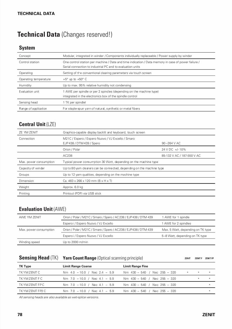
7/16/2019 YM Zenit Manual-LZE 044843 003en
http://slidepdf.com/reader/full/ym-zenit-manual-lze-044843-003en 78/83
78 ZENIT
TECHNICAL DATA
Technical Data (Changes reserved!)
System
Concept Modular, integrated in winder / Components individually replaceable / Power supply by winder
Control station One control station per machine / Date and time indication / Data memory in case of power failure /
Serial connection to industrial PC and to evaluation units
Operating Setting of the conventional clearing parameters via touch screen
Operating temperature +5° up to +50° C
Humidity Up to max. 95% relative humidity not condensing
Evaluation unit 1 AWE per spindle or per 2 spindles (depending on the machine type)
integrated in the electronics box of the spindle control
Sensing head 1 TK per spindlel
Range of application For staple-spun yarn of natural, synthetic or metal fibers
Central Unit (LZE)
ZE YM ZENIT Graphics-capable display backlit and keyboard, touch screen
Connection M21C / Espero / Espero Nuovo / VJ Excello / Smaro
EJP 438 / DTM 439 / Spero 90 –264 V AC
Orion / Polar 24 V DC +/- 10%
AC238 85-132 V AC / 187-550 V AC
Max. power consumption Typical power consumption 30 Watt, depending on the machine type
Capacity of winder Up to 80 yarn clearers can be connected, depending on the machine type
Groups Up to 12 yarn qualities, depending on the machine type
Dimension Ca. 483 x 266 x 120 mm (B x H x T)
Weight Approx. 6.0 kg
Printing Printout (PDF) via USB stick
Evaluation Unit (AWE)
AWE YM ZENIT Orion / Polar / M21C / Smaro / Spero / AC 238 / EJP 438 / DTM 439 1 AWE for 1 spindle
Espero i / Espero Nuovo / VJ Excello 1 AWE for 2 spindles
Max. power consumption Orion / Polar / M21C / Smaro / Spero / AC 238 / EJP 438 / DTM 439 Max. 5 Watt, depending on TK type
Espero i / Espero Nuovo / VJ Excello 5 –8 Watt, depending on TK type
Winding speed Up to 2000 m/min
Sensing Head (TK) Yarn Count Range (Optical scanning principle) ZENIT ZENIT F ZENIT FP
TK Type Limit Range Coarse Limit Range Fine
TK YM ZENIT C Nm 4.0 – 10.0 / Nec 2.4 – 5.9 Nm 430 – 540 / Nec 255 – 320 * * *
TK YM ZENIT F C Nm 7.0 – 10.0 / Nec 4.1 – 5.9 Nm 430 – 540 / Nec 255 – 320 * *
TK YM ZENIT FP C Nm 7.0 – 10.0 / Nec 4.1 – 5.9 Nm 430 – 540 / Nec 255 – 320 *
TK YM ZENIT FP2 C Nm 7.0 – 10.0 / Nec 4.1 – 5.9 Nm 430 – 540 / Nec 255 – 320 *
All sensing heads are also available as wet-splice versions.

7/16/2019 YM Zenit Manual-LZE 044843 003en
http://slidepdf.com/reader/full/ym-zenit-manual-lze-044843-003en 79/83
ZENIT 79
TECHNICAL DATA
Conventional Clearing According to Channels ZENIT ZENIT F ZENIT FP
Channel / Splice Channel
N Diameter limit for neps 1.5 to 7.0 * * *
DS Diameter limit for short faults 1.1 to 4.0 * * *
LS Limit for short fault length 1.0 cm to 10 cm * * *
DL Diameter limit for long faults 1.04 to 2.0 * * *
LL Limit for long fault length 6.0 cm to 200 cm * * *
–D Limit of diameter decrease -6% to - 60% * * *
–L Limit for thin place length 2.0 cm to 200 cm * * *
Upper Yarn
UpY Diameter limit for upper yarn detection 1.04 to 2.0 * * *
Clearing According to Classes / Fine Classification ZENIT ZENIT F ZENIT FP
Thick places 96 thick-place classes * * *
Diameter limit 1.2 to >7.0 * * *
Limit for fault length <0.5 cm to >70.0 cm * * *
Thin places 32 thin-place classes * * *
Diameter decrease <-35 % to -17 % * * *
Limit for fault length 2.0 cm to >70.0 cm * * *
Splice 128 Splice classes for short, long and thin faults * * *
Foreign matter 64 foreign matter classes each dark and bright * *
Darkness scale Dark 0.7 to >9.0 * *
Darkness scale Bright -0.7 to <-9.0 * *
Limit for fault length <0.5 cm to >8.0 cm * *
Classifying (Coarse Classification) ZENIT ZENIT F ZENIT FP
Thick places 19 thick-place classes * * *
Diameter limit 1.3 to >5.0 * * *
Limit for fault length 0.5 cm to >32.0 cm * * *
Thin places 4 thin-place classes* * *
Diameter decrease <-35 % to -20 % * * *
Limit for fault length 12.0 cm to >32.0 cm * * *
Splice 26 splice classes range overlapping of short, long an thin faults * * *
Foreign matter 16 foreign matter classes each dark and bright * *
Darkness scale Dark 0.7 to >6.0 * *
Darkness scale Bright -0.7 to <-6.0 * *
Limit for fault length <1.0 cm to >4.0 cm * *
Online Fault Classification
Per spindle and group with indication of cut and remaining faults of each class * * *

7/16/2019 YM Zenit Manual-LZE 044843 003en
http://slidepdf.com/reader/full/ym-zenit-manual-lze-044843-003en 80/83
80 ZENIT
TECHNICAL DATA
Data Acquisition ZENIT ZENIT F ZENIT FP
Mode FIRST : Classification window stops at selected length (10–1000 km) * * *
Mode LAST : Floating window. Selected length (10–1000 km) * * *
Mode CONE: Group: Floating window. Selected length (10–1000 km)
Spindle: The data are cleared when the length is reached
* * *
Clearing of Synthetic Foreign Matter (PP, PE, etc.) ZENIT ZENIT F ZENIT FP
Foreign matters PP PE Limit for electrical charge (sensitivity) 0.5 to 9.9 *
Reference length TK YM ZENIT FP C 0.5 cm to 4.0 cm *
Reference length TK YM ZENIT FP C P2 1.0 cm to 8.0 cm *
Yarn Monitoring ZENIT ZENIT F ZENIT FP
Yarn Count Channel (Cops Mix-up)
Diameter deviation ±3% to ±44% * * *
Reference length 10 m to 50 m * * *
Short Count Channel
Diameter deviation ±3% to ±44% * * *
Reference length 1 m to 32 m * * *
Cluster (Fault Accumulations)
Diameter Short Cluster 1.10 to 4.00 * * *
Long Cluster 1.04 to 2.00 * * *
Thin Cluster -6% to -60% * * *
Length Short Cluster 1.0 cm to 10 cm * * *
Long Cluster 6.0 cm to 200 cm * * *
Thin Cluster 2.0 cm to 200 cm * * *
Observation length 0.1 m to 80 m * * *
Maximum fault number relative to the set observation length 1 to 9999 * * *
F Cluster (Accumulations of Foreign Matter)
Detection according to 64 SIRO classes each dark and bright * *
Observation length 0.1 m to 80 m * *
Maximum fault number relative to the set observation length 1 to 9999 * *
Repetitions
Number of repetitions 0 to 9 * * *
Alarms
Automatic locking when reaching the limits of yarn fault cuts during start-up * * *
Automatic spindle locking when exceeding set number of yarn count cuts * * *
Automatic spindle locking when exceeding set number of fault cluster cut * * *
Automatic locking when reaching the set limits of foreign matter cuts during start-up * *
Automatic locking when reaching the set limits of foreign matter cluster cuts * *

7/16/2019 YM Zenit Manual-LZE 044843 003en
http://slidepdf.com/reader/full/ym-zenit-manual-lze-044843-003en 81/83
ZENIT 81
TECHNICAL DATA
LabPack (Option) ZENIT ZENIT F ZENIT FP
Surface Index (SFI)
Online quality data monitoring per spindle and group * * *
Surface Index Channel (SFI/D)
Floating or constant reerence 5.0 to 25.0 * * *
Limits +/– (maximum deviation rom reerence value) ±5% to ±40% * * *
Number o repetitions 0 to 5 * * *
Check length 80 m * * *
Automatic spindle locking when exceeding set number o Surace Index (SFI/D) channel cuts and
repetitions respectively
* * *
Variable CV Channel (VCV)
Limite +/- (maximum deviation rom mean value) ±5% to ±100% * * *
Number o repetitions 0 to 5 * * *
Check length 1 m to 50 m * * *
Automatic spindle locking when exceeding set number o Variable CV Channel (VCV) channel cuts and
repetitions respectively
* * *
Imperfections
Number of frequent yarn faults according to diameter limit per 1000 m
Neps Diameter limit >1.80 * * *
Thick Diameter limit >1.30 to <1.80 * * *
Thin Diameter limit <0.75 * * *
Number per meter
Small Positive deviation: Diameter limit 1.20 to 1.30 * * *
Negative deviation: Diameter limit 0.80 to 0.75 * * *
Number of frequent yarn faults according to length limit per 1000 m
4 yarn ault classes length-reerred in the range o 2 cm to 70 cm * * *
Positive and negative deviations with diameter limits >1.20 to <0.80 * * *
Installation Monitoring ZENIT ZENIT F ZENIT FP
Alarms
4 yarn ault classes length-reerred in the range o * * *
Positive and negative deviations with diameter limits * * *
Central Data Collection ZENIT ZENIT F ZENIT FP
Data Collection with Loepfe MillMaster
Central units can be linked with Ethernet * * *
Remote control o clearer parameter * * *
Central collection o quality data up to spindle level * * *
Central collection o production data up to spindle level * * *

7/16/2019 YM Zenit Manual-LZE 044843 003en
http://slidepdf.com/reader/full/ym-zenit-manual-lze-044843-003en 82/83

7/16/2019 YM Zenit Manual-LZE 044843 003en
http://slidepdf.com/reader/full/ym-zenit-manual-lze-044843-003en 83/83
ww.loepfe.co
Loepe Brothers Ltd.
CH-8623 Wetzikon/ Switzerland
Phone +41 43 488 11 11
Fax +41 43 488 11 00
www.loepe.com


![Gimp Manual[1]](https://static.dokumenty.site/doc/80x56/542e579b219acd46518b5854/gimp-manual1.jpg)