SBORNÍK X. KONFERENCE PIGMENTY A POJIVA CONFERENCE PROCEEDINGS OF THE X. CONFERENCE ON PIGMENTS AND BINDERS 6.–7. listopad 2017 06–07/11/2017 Kongres hotel JEZERKA, Seč, Česká republika Congress hotel JEZERKA, Seč, Czech Republic ORGANIZÁTOR/ORGANISER: CHEMAGAZÍN Ústav chemie a technologie makromolekulárních látek, Fakulta chemicko-technologická, Univerzita Pardubice
Transcript
SBORNÍKX. KONFERENCE PIGMENTY A POJIVACONFERENCE PROCEEDINGS OF THE X. CONFERENCE ON PIGMENTS AND BINDERS
6.–7. listopad 201706–07/11/2017
Kongres hotel JEZERKA, Seč, Česká republikaCongress hotel JEZERKA, Seč, Czech Republic
ORGANIZÁTOR/ORGANISER:CHEMAGAZÍN Ústav chemie a technologie makromolekulárních látek, Fakulta chemicko-technologická, Univerzita Pardubice
X. K
ON
FER
ENC
E PI
GM
ENTY
A P
OJI
VA •
X. C
ON
FERE
NC
E O
N P
IGM
ENTS
AN
D B
IND
ERS
ISBN 978-80-906269-2-8
Quelle: http://www.barcode-generator.de
KPP2017-obalka.indd 1 31.10.17 8:53
X. KONFERENCE PIGMENTY A POJIVA6.–7. listopad 2017 • Kongres hotel JEZERKA, Seč
www.pigmentyapojiva.cz
THE X. CONFERENCE ON PIGMENTS AND BINDERS06–07/11/2017 • Congress hotel JEZERKA, Seč, Czech Republic
Distribuci na Slovensku zajišťuje:[email protected]@eurosarm.cz+420 597 485 910+420 605 235 457
Disperzní pojivaPryskyřiceElastomerySíťovadla a tvrdidlaPigmenty a plnivaRozpouštědlaSmáčedlaDispergátoryReologické modi�kátoryKoalescentyOdpěňovačeHydrofobní aditivaMatovadla
Od 1.1.2018 pod značkou
SP
EKTR
OM
ETR
Y A
MIK
RO
SK
OPY
DL
OU
HÁ
ŽIV
OT
NO
ST
| V
ÝK
ON
NO
ST
| Š
IRO
KÁ
NA
BÍD
KA
PŘ
ÍSL
UŠ
EN
ST
VÍ
| J
ED
NO
DU
CH
Á O
BS
LU
HA
DIS
TR
IBU
TOR
ww
w.b
ruke
rop
tics
.cz
VE
RT
EX
80
v
LUM
OS
TE
NS
OR
II
s m
ikro
sko
pem
H
YP
ER
ION
ALP
HA
Mul
tiRA
MS
EN
TE
RR
A II
BR
AVO
FT-
IR s
pe
ktr
om
etr
y a
mik
rosk
op
y p
ro n
ejr
ůzn
ějš
í ap
lik
ace
od
R&
D a
ž p
o r
uti
nn
í prá
ci
Ko
mp
letn
í so
rtim
en
t R
aman
ov
ých
pří
stro
jů o
d h
and
he
ldu
až
po
po
kro
čil
ý R
&D
mik
rosk
op
Sborník/Conference proceedings
X. KONFERENCE PIGMENTY A POJIVA X. CONFERENCE ON PIGMENTS
AND BINDERS
Vydavatel/Editor:CHEMAGAZÍN s.r.o.
Vědecký výbor/Scientific committee:Dr. Ing. Petr ANTOŠ, Ph.D., EURING, EurChem – předseda
Prof. Ing. Andréa KALENDOVÁ, Ph.D.Prof. Ing. Pavla ROVNANÍKOVÁ, CSc.
Ing. Adolf GOEBEL, Ph.D.Ing. Michal POLEDNO, Ph.D.
Mgr. Petr RYŠÁNEK
Organizátor/Organiser:CHEMAGAZÍN s.r.o.,
Univerzita Pardubice, Fakulta chemicko-technologická, Ústav chemie a technologie makromolekulárních látek
THE POSSIBILITIES OF INFORMATION SEARCHING REGARDING THE FULFILLMENT OF LEGAL OBLIGATIONS FOR SVHC AND OTHER SUBSTANCES USED IN PAINTS, COATINGS AND BINDERSMOŽNOSTI HLEDÁNÍ INFORMACÍ Z HLEDISKA PLNĚNÍ LEGISLATIVNÍCH POVINNOSTÍ U SVHC A JINÝCH LÁTEK POUŽÍVANÝCH V BARVÁCH, POVLACÍCH A POJIVECHASRESAHEGNOVÁ Z. . . . . . . . . . . . . . . . . . . . . . . . . . . . . . . . . . . . . . . . . . . . . . . . . . . . . . . . . . 32
CONTROL OF SURFACE PROPERTIES OF TRANSPARENT WATERBORNE LACQUERS BASED ON ACRYLIC LATEXESŘÍZENÍ POVRCHOVÝCH VLASTNOSTÍ TRANSPARENTNÍCH VODOU ŘEDITELNÝCH LAKŮ NA BÁZI AKRYLÁTOVÝCH LATEXŮMACHOTOVÁ J., ČERNOŠKOVÁ E., RÜCKEROVÁ A., PUKOVÁ K. . . . . . . . . . . . . . . . . . . . . . . 33
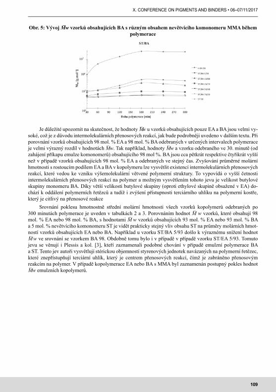
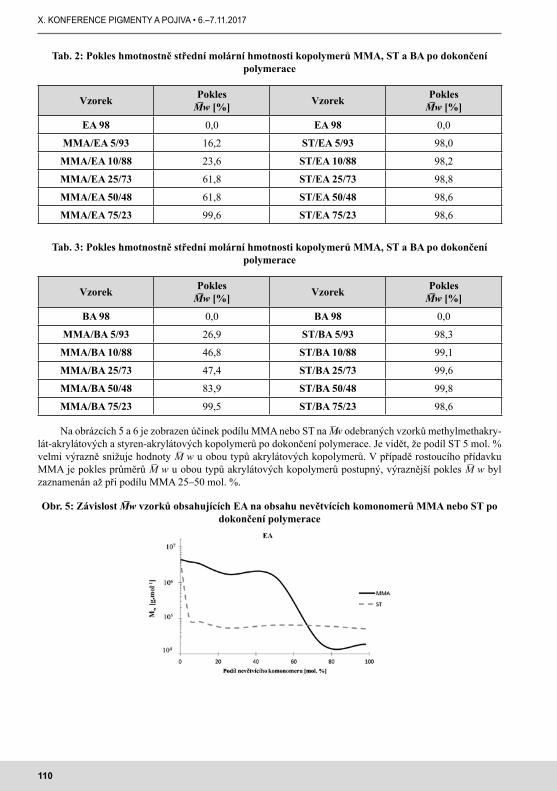
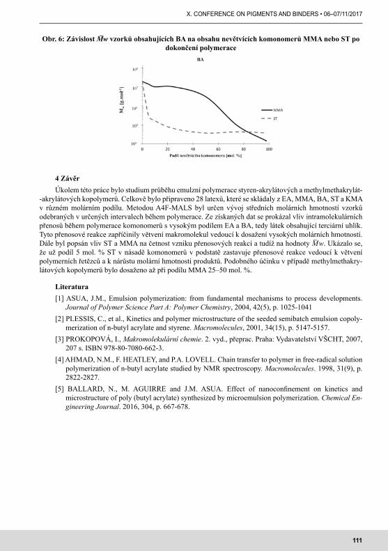
VÝVOJ MOLEKULOVÉ HMOTNOSTI STYREN-AKRYLÁTOVÝCH A METHYLMETHAKRYLÁT-AKRYLÁTOVÝCH EMULZNÍCH KOPOLYMERŮDEVELOPMENT OF THE MOLECULAR WEIGHT OF STYREN-ACRYLATE AND METHYLMETHACRYLATE-ACRYLATE EMULSION COPOLYMERSVÁLKA R., MACHOTOVÁ J., PODZIMEK Š. . . . . . . . . . . . . . . . . . . . . . . . . . . . . . . . . . . . . . . . 105
SYNTHESIS OF STAR POLYMERS APPLICABLE AS FILLER FOR POLYURETHANE COATINGS BY IONIC POLYMERIZATIONSYNTÉZA HVĚZDICOVITÝCH POLYMERŮ PRO POLYURETHANOVÉ NÁTĚRY POMOCÍ IONTOVÉ POLYMERACEBOHÁČIK P., PODZIMEK Š., ŠPAČEK V., BANDŽUCH J., MACHOTOVÁ J., KADLECOVÁ M. 112
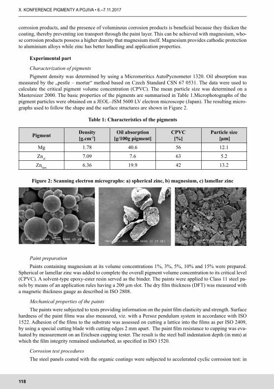
ANTICORROSIVE PROPERTIES OF ORGANIC COATINGS WITH A HIGH CONTENT OF ZINC AND MAGNESIUM METALANTIKOROZNÍ VLASTNOSTI ORGANICKÝCH POVLAKŮ S VYSOKÝM OBSAHEM KOVOVÉHO ZINKU A HOŘČÍKUVOLTROVÁ Z., KALENDOVÁ A., KOHL M., ŠEFL V., PROŠEK T. . . . . . . . . . . . . . . . . . . . . . . . 116
EFFECT OF CONDUCTIVE POLYMERS ON PROTECTIVE PROPERTIES OF ZINC-PIGMENTED COATINGSVLIV VODIVÝCH POLYMERŮ NA OCHRANNÉ VLASTNOSTI ZINKEM PIGMENTOVANÝCH NÁTĚROVÝCH HMOTNOVOTNÁ M., KOHL M., KALENDOVÁ A., ŠEFL V., PROŠEK T. . . . . . . . . . . . . . . . . . . . . . . . 121
COATING MATERIALS FOR ANTI-CORROSION PROTECTION CONTAINING CHEMICAL AND PHYSICAL PROPERTIES OF PIGMENTS BASED ON MIXED OXIDES OF IRONNÁTĚROVÉ HMOTY PRO ANTIKOROZNÍ OCHRANU S OBSAHEM CHEMICKY A FYZIKÁLNĚ PŮSOBÍCÍCH PIGMENTŮ NA BÁZI SMĚSNÝCH OXIDŮ ŽELEZAMIKEŠOVÁ Z., KALENDOVÁ A. . . . . . . . . . . . . . . . . . . . . . . . . . . . . . . . . . . . . . . . . . . . . . . . . . 125
STUDY OF THE ANTICORROSIVE PROPERTIES OF PAINTS WITH PIGMENTS SURFACE TREATED BY POLYPARAPHENYLENEDIAMINESTUDIUM ANTIKOROZNÍ ÚČINNOSTI NÁTĚROVÝCH HMOT S OBSAHEM PIGMENTŮ POVRCHOVĚ UPRAVENÝCH PPDAHÁJKOVÁ T., KALENDOVÁ A. . . . . . . . . . . . . . . . . . . . . . . . . . . . . . . . . . . . . . . . . . . . . . . . . . . 130
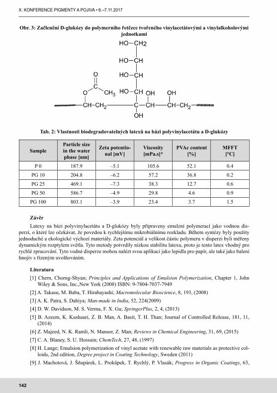
BIODEGRADABILNÍ POLYMERNÍ SYSTÉMY NA BÁZI D-GLUKÓZYD-GLUCOSE BASED BIODEGRADABLE POLYMERIC SYSTEMSPUKOVÁ K., MACHOTOVÁ J., MIKULÁŠEK P., RÜCKEROVÁ A. . . . . . . . . . . . . . . . . . . . . . . . 139
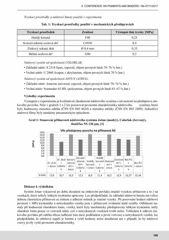
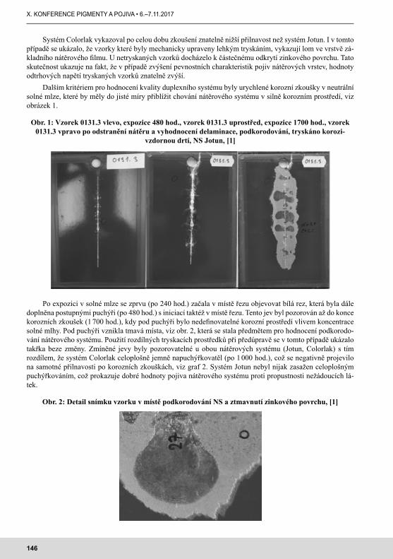
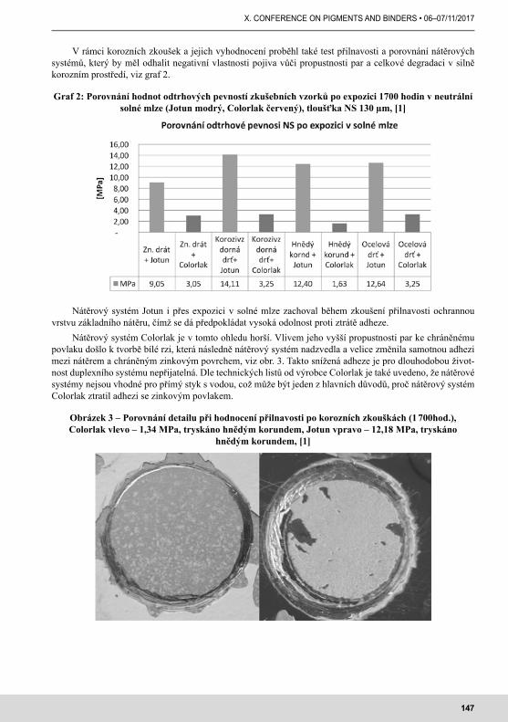
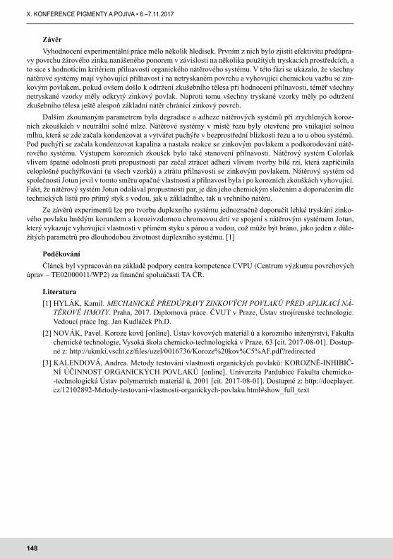
MECHANICKÉ PŘEDÚPRAVY ZINKOVÝCH POVRCHŮ A POROVNÁNÍ NÁTĚROVÝCH HMOT PRO DUPLEXNÍ SYSTÉMMECHANICAL PRETREATMENT OF ZINC SURFACE AND COMPARISON OF COATING MATERIALS FOR THE DUPLEX SYSTEMHYLÁK K., KUDLÁČEK J., KREIBICH V., SVOBODA J. . . . . . . . . . . . . . . . . . . . . . . . . . . . . . . . 149
11
X. CONFERENCE ON PIGMENTS AND BINDERS • 06–07/11/2017
WATER BASED COATINGS WITH IMPROVED FLAME STABILITY DUE TO PHOSPHAZENE DERIVATE APPLICATIONVODOU ŘEDITELNÉ NÁTĚRY SE ZVÝŠENOU ODOLNOSTÍ PROTI HOŘENÍ V DŮSLEDKU POUŽITÍ DERIVÁTU FOSFAZENURÜCKEROVÁ A., MACHOTOVÁ J., PUKOVÁ K., KALENDOVÁ A. . . . . . . . . . . . . . . . . . . . . . . 150
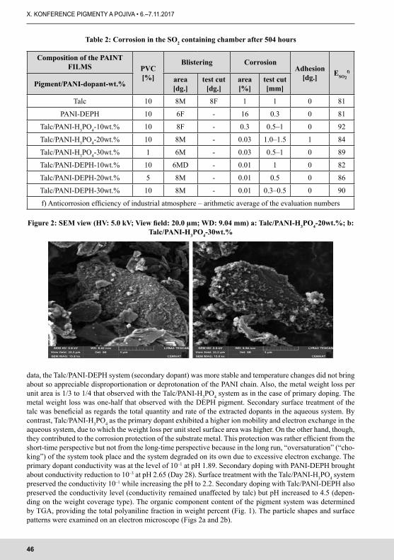
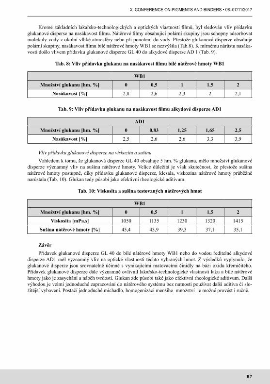
SummaryTitanium dioxide is the most widely used pigment in the world, its consumption is growing evenly. TiO2 is
a substance of unique properties usable in a number of applications that in many ways can not be replaced by other real substituents. The paper presents a list of the main application directions in pigment and
non-pigment use of TiO2, focuses on state and market changes and current segment threats.Key word
1. Úvod Oxid titaničitý je průmyslově vyráběn více než 100 let. Jeho základními užitnými vlastnostmi jsou bar-
vivost a bělost; tyto jsou průmyslově nejvíce využívány k pigmentaci hmot v různých aplikačních odvětvích, kde TiO2 je označován jako titanová běloba. Druhou v současnosti rozvíjející se možností, je užití TiO2 pro nepigmentové aplikace, tzn. zejména UV absorbce, katalýza a fotokatalýza.
2. Celosvětová spotřeba TiO2 a uplatnění v jednotlivých oblastechOxid titaničitý je nejvíce používaným pigmentem na světě, jeho spotřeba roste rovnoměrně s vývojem
HDP, v letošním roce dosáhne bezmála 6,5 milionů tun a je předpoklad, že do roku 2025 by mohla dosáhnout až 9 miliónů tun. Ve spotřebě je aktuálně dominující Čína, spotřebuje třetinu celosvětové produkce TiO2. Na druhém místě je Evropa následována Severní Amerikou.
Reakcí na spotřebu jsou rostoucí výrobní kapacity a to především v Asii. V Evropě lze až na drobné výjimky sledovat spíše útlum rozvoje produkce.
U řady výrobců TiO2 došlo v posledních letech ke značným změnám. Byly realizovány četné fúze, od-prodeje či vydělení výrob z hlavních oborů činností některých velkých společností. Před několika lety byly v čele produkce až desítky výrobců a to zvučných názvů, nyní je výsledkem pět nejsilnějších: CHEMOURS, VENATOR, TRONOX, KRONOS a čínský HENAN BILIONS. Pro průmysl barev to není optimální situace a to jak z důvodu stále menší konkurence na trhu, tak i rostoucích cen.
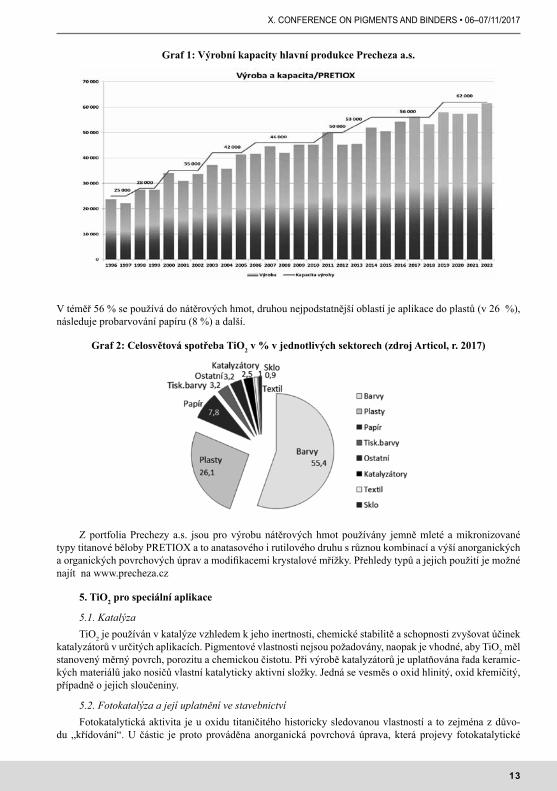
Co se týká zástupce domácí produkce, PRECHEZA a.s, jako moderní evropský výrobce s více než 120 letou historií nabízí pod obchodní značkami PRETIOX přes dvě desítky titanových bělob pro nátěrové hmoty, plasty, stavebnictví, pryž, papírenský průmysl, speciální aplikace (potravinářský a farmaceutický průmysl). Vývoj a produkce jednotlivých druhů jsou strategicky plánovány dle marketingových analýz a vývoje celo-světové poptávky. Aktuálně probíhá intenzifikace výrobní kapacity na 62 kt TiO2/rok.
3. Výroba, trendy a současný stav evropské legislativy Výroba probíhá celosvětově dvěma postupy- sulfátovým (s výtěžností TiO2 40–65%) a chloridovým
(93–96% TiO2), objevují se i nové technologie jako je ARGEX a nově i TiO2 ukrajinské společnosti VELTA, ale prozatím bez praktické instalace.
Ve smyslu řešení ekologické otázky výroby TiO2 jsou kalkulovány uhlíkové stopy jednotlivých výroben. Závody s neekologickou produkcí snižují výrobu nebo jsou zastaveny. Takto již bylo zastaveno na 70 přede-vším malých výrob v Číně.
Poslední hrozbou je nejen pro průmysl výroby TiO2, ale především pro veškeré navázané aplikační vý-roby návrh na změnu klasifikace TiO2 jako potenciálního karcinogenu (kategorie 2).
4. Tradiční použití titanové běloby Titanová nachází využití ve všech tradičních oblastech, kde jsou vítány její pigmentové vlastnosti.
13
X. CONFERENCE ON PIGMENTS AND BINDERS • 06–07/11/2017
V téměř 56 % se používá do nátěrových hmot, druhou nejpodstatnější oblastí je aplikace do plastů (v 26 %), následuje probarvování papíru (8 %) a další.
Graf 2: Celosvětová spotřeba TiO2 v % v jednotlivých sektorech (zdroj Articol, r. 2017)
Z portfolia Prechezy a.s. jsou pro výrobu nátěrových hmot používány jemně mleté a mikronizované typy titanové běloby PRETIOX a to anatasového i rutilového druhu s různou kombinací a výší anorganických a organických povrchových úprav a modifikacemi krystalové mřížky. Přehledy typů a jejich použití je možné najít na www.precheza.cz
5. TiO2 pro speciální aplikace
5.1. Katalýza TiO2 je používán v katalýze vzhledem k jeho inertnosti, chemické stabilitě a schopnosti zvyšovat účinek
katalyzátorů v určitých aplikacích. Pigmentové vlastnosti nejsou požadovány, naopak je vhodné, aby TiO2 měl stanovený měrný povrch, porozitu a chemickou čistotu. Při výrobě katalyzátorů je uplatňována řada keramic-kých materiálů jako nosičů vlastní katalyticky aktivní složky. Jedná se vesměs o oxid hlinitý, oxid křemičitý, případně o jejich sloučeniny.
5.2. Fotokatalýza a její uplatnění ve stavebnictvíFotokatalytická aktivita je u oxidu titaničitého historicky sledovanou vlastností a to zejména z důvo-
du „křídování“. U částic je proto prováděna anorganická povrchová úprava, která projevy fotokatalytické
Graf 1: Výrobní kapacity hlavní produkce Precheza a.s.
14
X. KONFERENCE PIGMENTY A POJIVA • 6.–7.11.2017
aktivity značně omezí. Pokud je ale proces fotokatalýzy řízen a zasazen do odolných matric, může být naopak přínosným nikoliv k jejich odbourávání, ale k odbourávání nežádoucích organických látek.
Současné trendy ve všech oblastech jsou orientovány na snižování nákladů na údržbu, ale i na ekolo-gickou prospěšnost staveb, potažmo vlastních stavebních hmot. Jedním z případů řešení mohou být úpravy povrchů stavebních hmot fotokatalyticky aktivním oxidem titaničitým, jenž je přidáván jako přímá příměs do hmoty (matrice). Fotokatalytické vlastnosti přispívají jak k dlouhodobě zlepšenému vzhledu povrchových vrstev, tak k eliminaci škodlivých polutantů z ovzduší.
6. Novinky z R&D Precheza a.s.
6.1. Vysoce povrchově upravené druhyNejdůležitějším z nově vyvinutých vysoce upravených rutilových druhů je speciální typ pro laminátový
papír RGLP2 s optimalizovanou anorganickou povrchovou úpravou, zlepšenou světlostálostí v porovnání s předchozí RGLP a vysokým stupněm zádržnosti v papírovině.
6.2. Nová povrchová úprava u RGU Na základě potřeby vyřazení výrobku RG18 bylo nutno optimalizovat vlastnosti RGU tak , aby splňoval
jeho kvalitativní parametry. Nový RGU je charakterizován kombinací výborné zapracovatelnosti a optic-kých vlastností a optimalizován v dispergovatelnosti (včetně možnosti použití dissolverů bez mlecího media) a v snížení spotřeby pojiva (jak v rozpouštědlových, tak i ve vodných systémech).
6.3 Nová povrchová úprava u plastikářského druhu RGXInovovaný materiál PRETIOX RGX byl vyvinut pro pigmentaci vícevrstvých fólií a PE určeného pro
laminaci na papír. Vyznačuje se zejména snadnější zapracovatelností do plastů, dobrou dispergovatelností a lepšími tokovými vlastnostmi. To umožňuje zpracovateli snadněji přepravovat pigment ve výrobě a zároveň vzhledem k lepší zapracovatelnosti zvýšit produkci své výroby (připravovat masterbatch o vyšší koncentraci při zachování požadované kvality).
7. Závěr I přes některé potenciální hrozby je předpoklad, že průmysl výroby TiO2 bude nadále v takové kondici,
jež mu umožní produkovat látku jedinečných vlastností. V mnoha ohledech nelze reálně TiO2 nahradit sub-stituenty, především s dodržením požadavku na docílení původních vlastností produktu, jež TiO2 obsahoval.
Další informace o portfoliu a aplikacích je možno získat na www.precheza.cz, respektive od pracovníků Technického servisu a.s. Precheza.
15
X. CONFERENCE ON PIGMENTS AND BINDERS • 06–07/11/2017
IS THERE ANY SCIENTIFIC REASONING FOR TiO2 CLASSIFICATION?EXISTUJÍ VĚDECKÉ DŮVODY PRO KLASIFIKACI TiO2?
SummaryFrench authority sent a proposal to ECHA for TiO2 classification as inhalation carcinogen cat.1B. This
proposal was refused with more than 500 statements during public consultation and only 7 statements were in agreement with the proposal. After close evaluation, the presented studies can be divided to animal and
human. Only animal studies with excessive and prolonged exposition to TiO2 dust provided some tumor indication. All human studies led to conclusion that there is no cancer relation to TiO2 exposition. Although scientific evidence indicates clearly that TiO2 is harmless, RAC committee recommends to classify it as the
inhalation carcinogen cat.2. We, as TiO2 producer are ready to take place in any reasonable study which can encourage rebuttal of this decision.
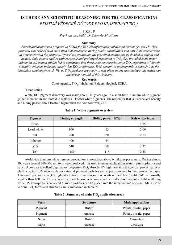
IntroductionWhite TiO2 pigment discovery was made about 100 years ago. In a short time, titanium white pigment
gained momentum and started to replace all known white pigments. The reason for that is its excellent opacity and hiding power, about twofold higher than the next follower, ZnS.
Table 1: White pigments overview
Pigment Tinting strength Hiding power [ft2/lb] Refraction index
Chalk 1.55
Lead white 100 15 2.00
ZnO 200 20 2.03
Lithopon 400 44
ZnS 540 58 2.37
TiO2 1150 115 2.55
Worldwide titanium white pigment production is nowadays above 6 mil.tons per annum. During almost 100 years around 300–500 mil.tons were produced. It is used in many applications mainly paints, plastics and paper. Above its excellent pigmentary properties TiO2 absorbs UV light and this feature can protect paint or plastics against UV induced deterioration if pigment particles are properly covered by inert protective layer. This same phenomenon (UV light absorption) is used in sunscreen where particles of rutile TiO2 are usually smaller than 100 nm. This decrease of particle size is accompanied with decrease in visible light scattering while UV absorption is enhanced as more particles can be placed into the same volume of cream. Main use of various TiO2 forms and structures are summarised in Table 2.
Table 2: Summary of main TiO2 application areas
Form Structure Main applications
Pigment Rutile Paints, plastic, paper
Pigment Anatase Paints, plastic, paper
Nano Rutile Cosmetics
Nano Anatase Catalysts
16
X. KONFERENCE PIGMENTY A POJIVA • 6.–7.11.2017
Although there is no sign of any negative issue during almost 100 years of TiO2 extensive use, French authority ANSES (ANSES – Agence nationale de sécurité sanitaire de l’alimentation, de l’environnement et du travail) sent to ECHA the proposal for harmonised classification and labelling. In this proposal ANSES suggested to classify TiO2 as an inhalation carcinogen cat.1B. Such classification would have de-trimental effect not only on TiO2 pigment production in Europe but more importantly on any downstream users – paint, plastic, paper industry, cosmetics and numerous smaller applications. Due to waste legislation, any material with more than 0.1% of TiO2 (which is almost anything, due to TiO2 omnipresence in natural materials) would be classified as hazardous waste and could not be recycled. After this proposal, more than 500 comments from all kinds of stakeholders were sent to ECHA most of them questioning and challenging this proposal. Only 7 comments were in favour to French proposal, almost exclusively from member state authorities, similar to ANSES.
Animal studiesANSES proposal covers all aspects of toxicology and all possible routes of administration. From all
covered fields, only inhalation route was indicated as producing carcinoma in laboratory animals. Authors evaluated 8 laboratory studies which are summarised in Table 3. One can clearly see that positive results (results in which lung tumors emerged) can be found only in studies with extreme dose connected with long term exposition and only in rats. Other animals do not manifest such results. The extreme dust concentration from first study can be observed only in volcanic eruptions and/or industrial disasters. Together with prolon-ged exposition it is totally unrealistic scenario. The visibility in such conditions could be computed [1] and for 250 mg/m3 the visibility is below 20 m. None of the mentioned studies comply with OECD guidelines for inhalation toxicity testing.
Table 3: Animal studies overview
Lee (1985) – extreme dust concentration (up to 250 mg/m3), inhalation, rats, 2 years, 6 hours a day, 5 days in week – positive
Heinrich (1995) – high concentration (over 10 mg/m3), rats and mice, inhalation, 2 years, 18 hours a day, 5 days in week – positive rats, negative mice
Muhle (1995) – reasonable concentration (5 mg/m3), rats, inhalation, 2 years, 6 hours a day, 5 days a weeku – negative
Thyssen (1978) – high concentration (15 mg/m3), inhalation, rats, 12 weeks, 6 hours a day, 5 days a week – negative
Pott (2005) – instillation, high dose (120 mg/animal) + Tween80, 2.5 years – positive
Xu (2010) – instillation in combination with positive carcinogen DHPN, high dose (50 mg/animal), 16 weeks, – positive
Yokohira (2009) – instillation in combination with positive carcinogen DHPN, reasonable dose 0.5 mg/animal – negative
Human studiesSeveral human studies (Table 4), both epidemiological or case control studies was quite recently perfor-
med. All of them with similar outcome – no relation of TiO2 exposure to any kind of carcinoma or standardised mortality. Some studies cover quite long period of exposition with average 30 years. Due to measures which are employed at TiO2 production plants concentration during exposition was lower than that used in animal studies. Workers in TiO2 producing plants are group of people exposed to TiO2 dust much regularly and in higher concentration than general public so if there is no risk for them the risk for general public is far lower..
17
X. CONFERENCE ON PIGMENTS AND BINDERS • 06–07/11/2017
Table 4: Human studies overview
Boffeta (2001) – 1923 persons, 857 confirmed lung tumours, 533 healthy subjects, 533 subjects with other tumours – no correlation between tumours occurrence and TiO2 exposition
Ramanakumar (2008) – 2748 persons, 1236 confirmed lung tumours, 1512 without tumours – no corre-lation between tumours occurrence and TiO2 exposition
Chen and Fayerweather (1988) – 1575 persons working in TiO2 production sites, exposition 0–20 mg/m3, – no correlation between tumours occurrence and TiO2 exposition, no fibrosis
Fryzek (2004) – 4241 persons, exposition 1–6 mg/m3, standardised mortality and lung tumours monito-red, SM same as expected in common population no correlation between tumours occurrence and mortality with TiO2 exposition
Boffeta (2004) – 15017 workers in 11 european companies producing TiO2, time span 27–47 years (altogether 371067 person-years), exposition 0.1–5 mg/m3, average 1.98 mg/m3, slightly increased lung carcinoma mortality (1.23) – differs according to country from 0.76 in Finland to 1.51 in Germany), no correlation between tumours occurrence and TiO exposition
Ellis (2012) – not mentioned in ANSES proposal [2], 5054 workers i TiO2 production (USA), followed in period 1935–2006, average observation time 29 years, 145151 person-years, mortality comparable to USA average, no correlation between TiO2 exposition and mortality from any cause
Discussion and conclusionsResults suggests that rats are overly sensitive to dust exposure and develop lung cancer due to lung over-
load readily (http://www.ecetoc.org/report2/species-differences-and-mechanisms-of-lung-tumour-formati-on-in-rats/relevance-of-lung-overload-for-humans/). This was confirmed several times and it is known that outcome from animal studies are often misleading (http://www.pcrm.org/research/healthcare-professionals/research-compendium/an-examination-of-animal-experiments; Animal models of stroke: are they relevant to human disease? doi: 10.1161/01.STR.21.1.1 Stroke. 1990;21:1–3), . Animal studies were even used to prevent identification of cigarette smoke as carcinogenic [3]. (cit. “There have been many such experiments here and abroad, and none have been able to produce carcinoma of the lung in animals.”). Only extensive human epi-demiological data found clear relation of cigarette smoke exposure and lung cancer.
Although published data seems to be clearly against any TiO2 categorisation RAC decided to recommend that TiO2 should be classed to inhalation carcinogen category 2. Such classification if implemented could be problematic not only to TiO2 producers but maybe in much greater extend to our customers. Some legislation already enforced in EU will trigger immediate consequences for TiO2 use and TiO2 containing waste disposal. During RAC meeting several issues were raised, not all RAC members were favourable to classification and more importantly TiO2 mode of action was suggested to be the same as in other PSLT (poorly soluble low toxicity) particles, which opens door to classify any dust material.
We are ready to cooperate in any reasonable research which could address TiO2 carcinogenity to close data gaps perceived by some stakeholders and RAC committee members to either confirm or rebut this sug-gestion to classify TiO2.
References[1] BADDOCK, M.C. et al, 2014. A visibility and total suspended dust relationship. Atmospheric Envi-
ronment, 89, pp. 329–336[2] Ellis, E.D. et al.: Occupational exposure and mortality among workers at three titanium dioxide
plants, American Journal of Industrial Medicine, Volume 56, Issue 3, p. 282–291, March 2013[3] Clarence C. Little, Sc.D. Some Phases of the Problem of Smoking and Lung Cancer, N Engl J Med
1961; 264:1241–1245 June 15, 1961
18
X. KONFERENCE PIGMENTY A POJIVA • 6.–7.11.2017
COMPOSITE PHOTOCATALYST BASED ON TiO2 – ACTIVE CARBONKOMPOZITNÍ FOTOKATALYZÁTORY NA BÁZI TiO2 – AKTIVNÍ UHLÍ
1 Technopark Kralupy University of Chemistry and Technology Prague2 Department of Inorganic Technology, University of Chemistry and Technology Prague
SummaryComposite photocatalysts based on TiO2 – active carbon (AC) are promising materials for pollutant removal due to the combination of high adsorption ability of AC and photocatalytic activity of TiO2. The objective of this work was to determine the influence of the TiO2/AC fraction on the photocatalytic efficiency of pollutant removal in gaseous (using standard ISO methods) and liquid phase. It was observed that the composite pho-tocatalyst TiO2-AC exhibits a synergistic increase of pollutant removing ability which can be demonstrated
on removal of NOx from the gaseous phase. In the case of pure TiO2, under UV irradiation the concentration of inlet NO decreases but the concentration of NO2 (in fact more toxic than the initial NO) increases. This is
caused by the accumulation of HNO3 on the surface of TiO2 which reacts with NO to NO2. Composites TiO2-AC exhibit much higher resistance to nitric acid accumulation compared to pure TiO2 due to the
significantly higher surface area (460 m2/g) in relation to pure TiO2 (45 m2/g).Key words
TiO2, active carbon, photocatalysis
Introduction Semiconductor photocatalysis represents a promising method which can be applied in various cleaning
application (removal of dyes, volatile organic carbon (VOC)) or in the form of self-cleaning surfaces which are not susceptible to soiling (typical facade paints containing photoactive TiO2). This paper is focused on the preparation and characterization of composite photocatalysts containing TiO2 – active carbon (AC) which combine high surface area of the active carbon and photocatalytic activity of TiO2. Photocatalytic activity of prepared materials was tested via removal of an aqueous pollutant – the azodye Acid Orange 7 in a batch photoreactor and also via removal of gaseous pollutants using ISO standard methods.
Experimental partComposite photocatalysts of various ratios of commercial TiO2 P25 (Evonik) and Active Carbon, (Penta
Chemicals) were prepared as follows. In the first method, a suspension with 2.5 g/dm3 of TiO2 and the corre-sponding amount of active carbon (AC) was prepared to obtain samples with different AC/TiO2 ratios from 7–70% [1]. The second method of preparation is based on hydrothermal treatment of suspensions of TiO2 and AC using NaOH (1.5 mol/dm3) as a mineralizer. The hydrothermal treatment was performed at 150 °C and a pressure of 50 bar for 12 hours [2].
Photocatalytic activity was determined according to standard ISO methods (ISO 22197-1 removal of NOx and ISO 22197-2 removal of acetaldehyde). Photocatalytic activity was also determined using a stirred batch photoreactor using Acid Orange 7 as a model compound. From the powder material, particle layers were prepared (using a sedimentation method) with a constant amount of TiO2 (0.5 mgTiO2/cm2).
Results and discussion
XRD, BET and particle size characterizationAccording to XRD, the phase composition of photocatalyst prepared by the mixing method, or by the
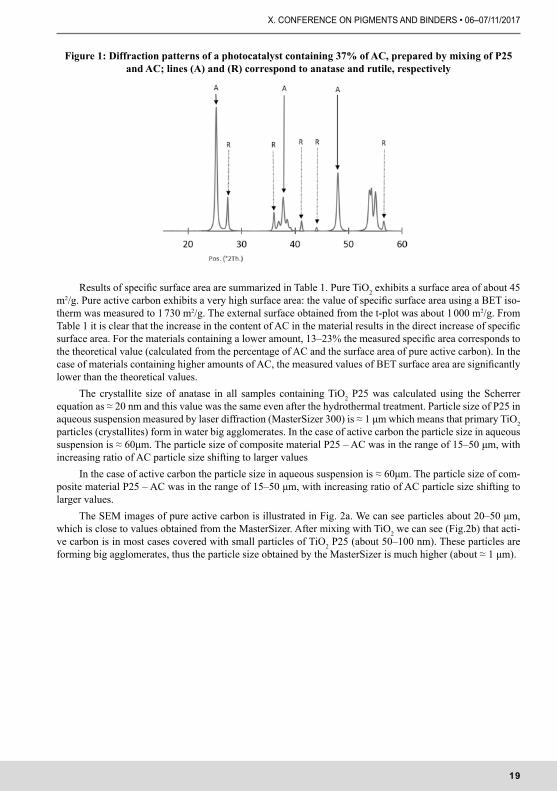
mixing method with subsequent hydrothermal treatment corresponds to a composition of original P25 photo-catalyst consisting of ~75% of anatase and ~25% of rutile. Thus the hydrothermal treatment has no influence on anatase/rutile composition. XRD patterns of photocatalysts containing 37% of AC prepared by mixing method are shown in Fig. 1.
19
X. CONFERENCE ON PIGMENTS AND BINDERS • 06–07/11/2017
Figure 1: Diffraction patterns of a photocatalyst containing 37% of AC, prepared by mixing of P25 and AC; lines (A) and (R) correspond to anatase and rutile, respectively
Results of specific surface area are summarized in Table 1. Pure TiO2 exhibits a surface area of about 45 m2/g. Pure active carbon exhibits a very high surface area: the value of specific surface area using a BET iso-therm was measured to 1 730 m2/g. The external surface obtained from the t-plot was about 1 000 m2/g. From Table 1 it is clear that the increase in the content of AC in the material results in the direct increase of specific surface area. For the materials containing a lower amount, 13–23% the measured specific area corresponds to the theoretical value (calculated from the percentage of AC and the surface area of pure active carbon). In the case of materials containing higher amounts of AC, the measured values of BET surface area are significantly lower than the theoretical values.
The crystallite size of anatase in all samples containing TiO2 P25 was calculated using the Scherrer equation as ≈ 20 nm and this value was the same even after the hydrothermal treatment. Particle size of P25 in aqueous suspension measured by laser diffraction (MasterSizer 300) is ≈ 1 μm which means that primary TiO2 particles (crystallites) form in water big agglomerates. In the case of active carbon the particle size in aqueous suspension is ≈ 60μm. The particle size of composite material P25 – AC was in the range of 15–50 μm, with increasing ratio of AC particle size shifting to larger values
In the case of active carbon the particle size in aqueous suspension is ≈ 60μm. The particle size of com-posite material P25 – AC was in the range of 15–50 μm, with increasing ratio of AC particle size shifting to larger values.
The SEM images of pure active carbon is illustrated in Fig. 2a. We can see particles about 20–50 μm, which is close to values obtained from the MasterSizer. After mixing with TiO2 we can see (Fig.2b) that acti-ve carbon is in most cases covered with small particles of TiO2 P25 (about 50–100 nm). These particles are forming big agglomerates, thus the particle size obtained by the MasterSizer is much higher (about ≈ 1 μm).
20
X. KONFERENCE PIGMENTY A POJIVA • 6.–7.11.2017
Table 1: Values of specific surface area measured using BET isotherm for samples with various AC
Sample BET Sg [m2/g]
pure TiO2 P25 45
pure active carbon 1732
mixing method TiO2-AC 13 % 226
mixing method TiO2-AC 23 % 340
mixing method TiO2-AC 37 % 460
mixing method TiO2-AC 50 % 608
mixing method TiO2-AC 70 % 697
mixing method with subsequent hydrothermal treatment TiO2-AC 23 % 400
mixing method with subsequent hydrothermal treatment TiO2-AC 37 % 643
mixing method with subsequent hydrothermal treatment TiO2-AC 50% 868
mixing method with subsequent hydrothermal treatment TiO2-AC 70% 1 216
Figure 2a: SEM images of pure active carbon
Figure 2b: SEM images of pure active carbon covered by TiO2 P25 (sample TiO2-AC 23%)
21
X. CONFERENCE ON PIGMENTS AND BINDERS • 06–07/11/2017
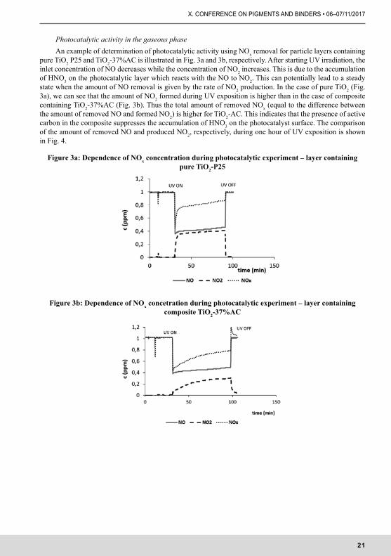
Photocatalytic activity in the gaseous phaseAn example of determination of photocatalytic activity using NOx removal for particle layers containing
pure TiO2 P25 and TiO2-37%AC is illustrated in Fig. 3a and 3b, respectively. After starting UV irradiation, the inlet concentration of NO decreases while the concentration of NO2 increases. This is due to the accumulation of HNO3 on the photocatalytic layer which reacts with the NO to NO2. This can potentially lead to a steady state when the amount of NO removal is given by the rate of NO2 production. In the case of pure TiO2 (Fig. 3a), we can see that the amount of NO2 formed during UV exposition is higher than in the case of composite containing TiO2-37%AC (Fig. 3b). Thus the total amount of removed NOx (equal to the difference between the amount of removed NO and formed NO2) is higher for TiO2-AC. This indicates that the presence of active carbon in the composite suppresses the accumulation of HNO3 on the photocatalyst surface. The comparison of the amount of removed NO and produced NO2, respectively, during one hour of UV exposition is shown in Fig. 4.
Figure 3a: Dependence of NOx concentration during photocatalytic experiment – layer containing pure TiO2-P25
Figure 3b: Dependence of NOx concetration during photocatalytic experiment – layer containing composite TiO2-37%AC
22
X. KONFERENCE PIGMENTY A POJIVA • 6.–7.11.2017
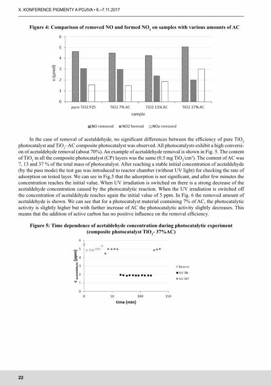
Figure 4: Comparison of removed NO and formed NO2 on samples with various amounts of AC
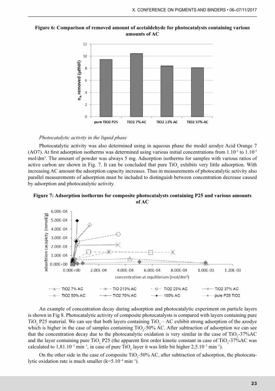
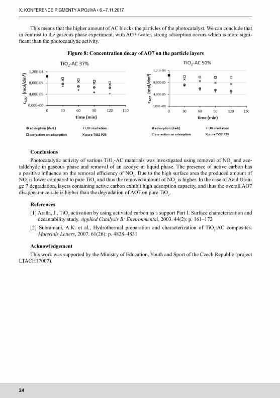
In the case of removal of acetaldehyde, no significant differences between the efficiency of pure TiO2 photocatalyst and TiO2–AC composite photocatalyst was observed. All photocatalysts exhibit a high conversi-on of acetaldehyde removal (about 70%). An example of acetaldehyde removal is shown in Fig. 5. The content of TiO2 in all the composite photocatalyst (CP) layers was the same (0.5 mg TiO2/cm2). The content of AC was 7, 13 and 37 % of the total mass of photocatalyst. After reaching a stable initial concentration of acetaldehyde (by the pass mode) the test gas was introduced to reactor chamber (without UV light) for checking the rate of adsorption on tested layer. We can see in Fig.5 that the adsorption is not significant, and after few minutes the concentration reaches the initial value. When UV irradiation is switched on there is a strong decrease of the acetaldehyde concentration caused by the photocatalytic reaction. When the UV irradiation is switched off the concentration of acetaldehyde reaches again the initial value of 5 ppm. In Fig. 6 the removed amount of acetaldehyde is shown. We can see that for a photocatalyst material containing 7% of AC, the photocatalytic activity is slightly higher but with further increase of AC the photocatalytic activity slightly decreases. This means that the addition of active carbon has no positive influence on the removal efficiency.
Figure 5: Time dependence of acetaldehyde concentration during photocatalytic experiment (composite photocatalyst TiO2- 37%AC)
23
X. CONFERENCE ON PIGMENTS AND BINDERS • 06–07/11/2017
Figure 6: Comparison of removed amount of acetaldehyde for photocatalysts containing various amounts of AC
Photocatalytic activity in the liquid phasePhotocatalytic activity was also determined using in aqueous phase the model azodye Acid Orange 7
(AO7). At first adsorption isotherms was determined using various initial concentrations from 1.10-3 to 1.10-5 mol/dm3. The amount of powder was always 5 mg. Adsorption isotherms for samples with various ratios of active carbon are shown in Fig. 7. It can be concluded that pure TiO2 exhibits very little adsorption. With increasing AC amount the adsorption capacity increases. Thus in measurements of photocatalytic activity also parallel measurements of adsorption must be included to distinguish between concentration decrease caused by adsorption and photocatalytic activity.
Figure 7: Adsorption isotherms for composite photocatalysts containing P25 and various amounts of AC
An example of concentration decay during adsorption and photocatalytic experiment on particle layers is shown in Fig 8. Photocatalytic activity of composite photocatalysts is compared with layers containing pure TiO2 P25 material. We can see that both layers containing TiO2 – AC exhibit strong adsorption of the azodye which is higher in the case of samples containing TiO2-50% AC. After subtraction of adsorption we can see that the concentration decay due to the photocatalytic oxidation is very similar in the case of TiO2-37%AC and the layer containing pure TiO2 P25 (the apparent first order kinetic constant in case of TiO2-37%AC was calculated to 1,81.10–3 min–1, in case of pure TiO2 layer it was little bit higher 2,5.10–3 min–1).
On the other side in the case of composite TiO2-50% AC, after subtraction of adsorption, the photocata-lytic oxidation rate is much smaller (k=5.10–4 min–1).
24
X. KONFERENCE PIGMENTY A POJIVA • 6.–7.11.2017
This means that the higher amount of AC blocks the particles of the photocatalyst. We can conclude that in contrast to the gaseous phase experiment, with AO7 /water, strong adsorption occurs which is more signi-ficant than the photocatalytic activity.
Figure 8: Concentration decay of AO7 on the particle layers
ConclusionsPhotocatalytic activity of various TiO2-AC materials was investigated using removal of NOx and ace-
taldehyde in gaseous phase and removal of an azodye in liquid phase. The presence of active carbon has a positive influence on the removal efficiency of NOx. Due to the high surface area the produced amount of NO2 is lower compared to pure TiO2 and thus the removed amount of NOx is higher. In the case of Acid Oran-ge 7 degradation, layers containing active carbon exhibit high adsorption capacity, and thus the overall AO7 disappearance rate is higher than the degradation of AO7 on pure TiO2.
References[1] Araña, J., TiO2 activation by using activated carbon as a support Part I. Surface characterization and
decantability study. Applied Catalysis B: Environmental, 2003. 44(2): p. 161–172[2] Subramani, A.K. et al., Hydrothermal preparation and characterization of TiO2:AC composites.
Materials Letters, 2007. 61(26): p. 4828–4831
AcknowledgementThis work was supported by the Ministry of Education, Youth and Sport of the Czech Republic (project
LTACH17007).
25
X. CONFERENCE ON PIGMENTS AND BINDERS • 06–07/11/2017
α-Fe2O3/TiO2 PHOTOANODES FOR ENERGY AND ENVIRONMENTAL APPLICATIONS
α-Fe2O3/TiO2 FOTOANODY PRO ENERGETICKÉ A ENVIRONMENTÁLNÍ APLIKACE
1 Department of Inorganic Technology, University of Chemistry and Technology, Technická 5, 166 28 Prague 6, Czech Republic
2 Institute of Physics ASCR, v.v.i., Na Slovance 2 182 21 Prague 8 Czech Republic
SummaryIron oxide (α-Fe2O3) is a promising photoanode material for either photoassisted water electrolysis or
photoelectrochemical (PEC) oxidation of water pollutants. This paper deals with the preparation of α-Fe2O3/TiO2 bilayer films with the aim of minimising their low stability in acidic media and thus improve the PEC efficiency. Bi-layers of TiO2 and α-Fe2O3 were prepared on conductive fluorine doped tin oxide (FTO) glass by subsequent deposition of i) α-Fe2O3 layers prepared by high-power impulse magnetron
sputtering (HiPIMS) followed by annealing at 650–750 °C and ii) TiO2 (sol-gel method using dip-coating). The influence of annealing tempereature and hematite layer thickness on the composition and photoelectro-
1 IntroductionTitania (TiO2) and hematite (α-Fe2O3) have potential applications as semiconducting photoanodes for
either hydrogen production via photoassisted water electrolysis or photoelectrochemical (PEC) oxidation of water pollutants. The advantages of TiO2 are its low price, high stability and nontoxicity. However, only a very small part of sunlight (4%) is absorbed. Iron oxide (α-Fe2O3) has a favourable band gap (2.0–2.2 eV), which allows absorbing a substantial fraction of the solar spectrum, resulting in the theoretical maximum power con-version efficiency of 27%. But there are also limitations, e.g. the nonideal position of hematite’s conduction band, which is too low for spontaneous water reduction, and its low stability in acidic media. The latter can be minimised by coverering it by a thin titania film.
Hematite semiconducting Fe2O3 thin films have already been deposited by reactive high power impulse magnetron sputtering (HIPIMS) [1–4]. A pure iron target was reactively sputtered in an Ar + O2 gas mixture. Dense hematite Fe2O3 thin films with n-type conductivity and high photocurrents in a junction with an alkaline electrolyte (up to ≈ 1 mA/cm2 at 100 mW AM1.5 spectrum) were obtained by this technique. The HIPIMS mode of magnetron discharge excitation was responsible for the high ionization degree of sputtered particles, high ion flux to the substrate during the working pulse and, simultaneously, low heating flux to the substrate. Due to the back attraction of ionized sputtered particles to the target the deposition rate of HIPIMS magnetron is usually lower than in case of DC magnetron systems [5, 6].
Since only a small thickness (20–100 nm) of Fe2O3 hematite semiconductor films is usually needed due to the short diffusion length of carriers, the HIPIMS technology is perspective for this application. The aim of the present work was the preparation of bilayer α-Fe2O3/TiO2 thin films on FTO substrate. The influence of an-nealing tempereature and α-Fe2O3 layer thickness on the composition and photoelectrochemical performance of such photoanodes was evaluated.
2 Experimental
Film depositionAll films were prepared on conductive fluorine doped tin oxide (FTO) glass (TCO22-15, Solaronix,
Switzerland).
26
X. KONFERENCE PIGMENTY A POJIVA • 6.–7.11.2017
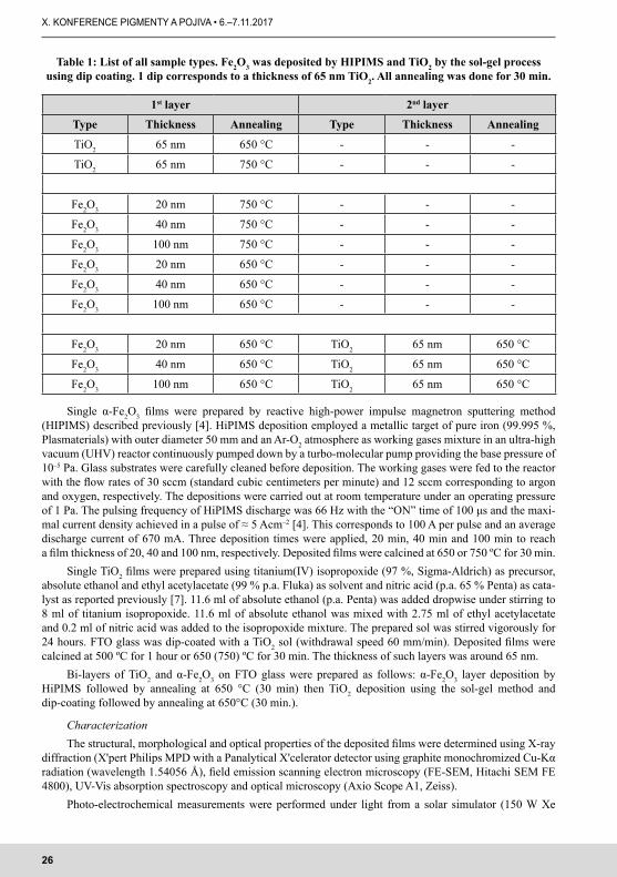
Table 1: List of all sample types. Fe2O3 was deposited by HIPIMS and TiO2 by the sol-gel process using dip coating. 1 dip corresponds to a thickness of 65 nm TiO2. All annealing was done for 30 min.
1st layer 2nd layer
Type Thickness Annealing Type Thickness Annealing
TiO2 65 nm 650 °C - - -
TiO2 65 nm 750 °C - - -
Fe2O3 20 nm 750 °C - - -
Fe2O3 40 nm 750 °C - - -
Fe2O3 100 nm 750 °C - - -
Fe2O3 20 nm 650 °C - - -
Fe2O3 40 nm 650 °C - - -
Fe2O3 100 nm 650 °C - - -
Fe2O3 20 nm 650 °C TiO2 65 nm 650 °C
Fe2O3 40 nm 650 °C TiO2 65 nm 650 °C
Fe2O3 100 nm 650 °C TiO2 65 nm 650 °C
Single α-Fe2O3 films were prepared by reactive high-power impulse magnetron sputtering method (HIPIMS) described previously [4]. HiPIMS deposition employed a metallic target of pure iron (99.995 %, Plasmaterials) with outer diameter 50 mm and an Ar-O2 atmosphere as working gases mixture in an ultra-high vacuum (UHV) reactor continuously pumped down by a turbo-molecular pump providing the base pressure of 10–5 Pa. Glass substrates were carefully cleaned before deposition. The working gases were fed to the reactor with the flow rates of 30 sccm (standard cubic centimeters per minute) and 12 sccm corresponding to argon and oxygen, respectively. The depositions were carried out at room temperature under an operating pressure of 1 Pa. The pulsing frequency of HiPIMS discharge was 66 Hz with the “ON” time of 100 μs and the maxi-mal current density achieved in a pulse of ≈ 5 Acm–2 [4]. This corresponds to 100 A per pulse and an average discharge current of 670 mA. Three deposition times were applied, 20 min, 40 min and 100 min to reach a film thickness of 20, 40 and 100 nm, respectively. Deposited films were calcined at 650 or 750 ºC for 30 min.
Single TiO2 films were prepared using titanium(IV) isopropoxide (97 %, Sigma-Aldrich) as precursor, absolute ethanol and ethyl acetylacetate (99 % p.a. Fluka) as solvent and nitric acid (p.a. 65 % Penta) as cata-lyst as reported previously [7]. 11.6 ml of absolute ethanol (p.a. Penta) was added dropwise under stirring to 8 ml of titanium isopropoxide. 11.6 ml of absolute ethanol was mixed with 2.75 ml of ethyl acetylacetate and 0.2 ml of nitric acid was added to the isopropoxide mixture. The prepared sol was stirred vigorously for 24 hours. FTO glass was dip-coated with a TiO2 sol (withdrawal speed 60 mm/min). Deposited films were calcined at 500 ºC for 1 hour or 650 (750) ºC for 30 min. The thickness of such layers was around 65 nm.
Bi-layers of TiO2 and α-Fe2O3 on FTO glass were prepared as follows: α-Fe2O3 layer deposition by HiPIMS followed by annealing at 650 °C (30 min) then TiO2 deposition using the sol-gel method and dip-coating followed by annealing at 650°C (30 min.).
CharacterizationThe structural, morphological and optical properties of the deposited films were determined using X-ray
diffraction (X'pert Philips MPD with a Panalytical X'celerator detector using graphite monochromized Cu-Kα radiation (wavelength 1.54056 Å), field emission scanning electron microscopy (FE-SEM, Hitachi SEM FE 4800), UV-Vis absorption spectroscopy and optical microscopy (Axio Scope A1, Zeiss).
Photo-electrochemical measurements were performed under light from a solar simulator (150 W Xe
27
X. CONFERENCE ON PIGMENTS AND BINDERS • 06–07/11/2017
arc lamp (Newport) with AM1.5G filter, irradiance 1 sun (100 mW/cm2) or monochromatic LED irradiation (360–620 nm) using a three electrode arrangement in a three compartment glass cell. An aqueous solution of NaOH was used as electrolyte. α-Fe2O3 on FTO glass was used as photoanode, platinum sheet as cathode and Ag/AgCl as reference electrode (0.196 V vs. SHE). The exposed photoanode area (1 cm2) was defined by Teflon tape. The electric contact was made by pressing stainless steel to the upper part of FTO layer, not covered by α-Fe2O3.
Linear voltammetry was carried out with a sweep rate of 5 mV/s under periodical (5 s light/5 s dark) front side illumination of the electrolyte/electrode interface (“EE”, through the electrolyte). The photocurrents were measured using a Voltalab10 PGZ-100 potentiostat (software VoltaMaster 4). The starting potential was around –0.5 V (Ag/AgCl), sweeping was positive towards the end potential in the range 0.7– 1.0 V (vs. Ag/AgCl). If not specified, the irradiation was from the electrolyte/electrode interface (EE) but for selected films also irradiation from the substrate/electrode interface (SE) was used.
3 Results
3.1 HIPIMS hematite films, influence of annealing temperature and layer thickness.
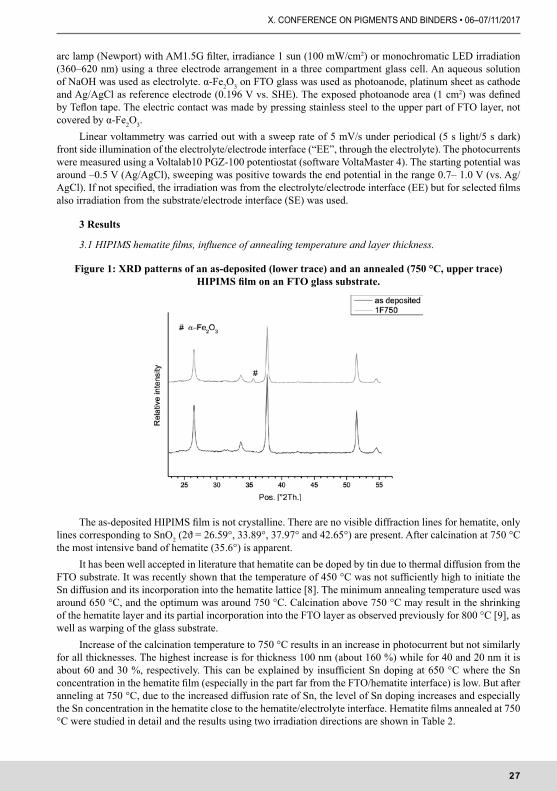
Figure 1: XRD patterns of an as-deposited (lower trace) and an annealed (750 °C, upper trace) HIPIMS film on an FTO glass substrate.
The as-deposited HIPIMS film is not crystalline. There are no visible diffraction lines for hematite, only lines corresponding to SnO2 (2ϑ = 26.59°, 33.89°, 37.97° and 42.65°) are present. After calcination at 750 °C the most intensive band of hematite (35.6°) is apparent.
It has been well accepted in literature that hematite can be doped by tin due to thermal diffusion from the FTO substrate. It was recently shown that the temperature of 450 °C was not sufficiently high to initiate the Sn diffusion and its incorporation into the hematite lattice [8]. The minimum annealing temperature used was around 650 °C, and the optimum was around 750 °C. Calcination above 750 °C may result in the shrinking of the hematite layer and its partial incorporation into the FTO layer as observed previously for 800 °C [9], as well as warping of the glass substrate.
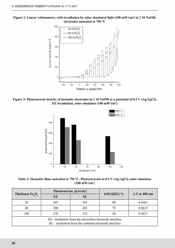
Increase of the calcination temperature to 750 °C results in an increase in photocurrent but not similarly for all thicknesses. The highest increase is for thickness 100 nm (about 160 %) while for 40 and 20 nm it is about 60 and 30 %, respectively. This can be explained by insufficient Sn doping at 650 °C where the Sn concentration in the hematite film (especially in the part far from the FTO/hematite interface) is low. But after anneling at 750 °C, due to the increased diffusion rate of Sn, the level of Sn doping increases and especially the Sn concentration in the hematite close to the hematite/electrolyte interface. Hematite films annealed at 750 °C were studied in detail and the results using two irradiation directions are shown in Table 2.
28
X. KONFERENCE PIGMENTY A POJIVA • 6.–7.11.2017
Figure 2: Linear voltammetry with irradiation by solar simulated light (100 mW/cm2) in 1 M NaOH; electrodes annealed at 750 °C
Figure 3: Photocurrent density of hematite electrodes in 1 M NaOH at a potential of 0.5 V (Ag/AgCl), EE irradiation, solar simulator (100 mW/cm2)
Table 2: Hematite films annealed at 750 °C, Photocurrents at 0.5 V (Ag/AgCl), solar simulator (100 mW/cm2)
Thickness Fe2O3
Photocurrent, [µA/cm2]i(SE)/i(EE) % 1-T at 400 nm
EE SE
20 445 365 80 0.6461
40 380 265 70 0.8625
100 270 132 50 0.9631
EE– irradiation from the electrolyte/electrode interfaceSE – irradiation from the substrate/electrode interface
29
X. CONFERENCE ON PIGMENTS AND BINDERS • 06–07/11/2017
The decrease of photocurrent with an increase of layer thickness has been observed already before [3] and is connected with the short diffusion length. Sn doping by diffusion from the FTO substrate can compens-ate it but not homogeneously throught the bulk of the film. The photocurrents for the SE irradiation are lower than for EE irradiation. This is again due to the low minority carrier diffusion length: carriers formed far away from the semiconductor / electrolyte interface recombine before reaching the space charge region – especially in thicker electrodes.
3.2 Bi- layer hematite/TiO2
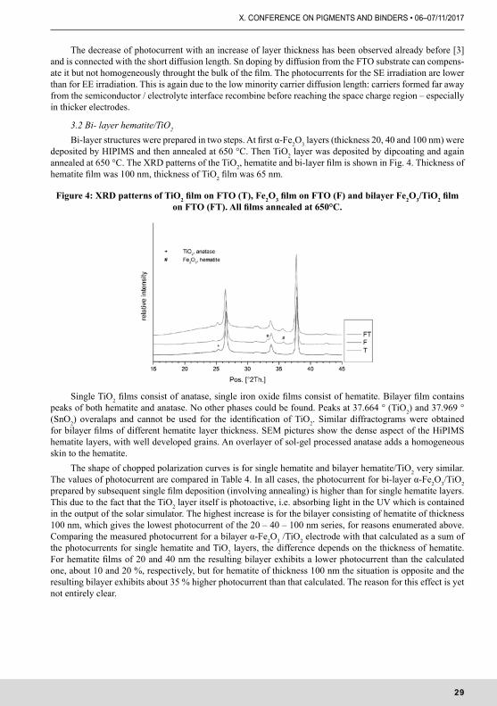
Bi-layer structures were prepared in two steps. At first α-Fe2O3 layers (thickness 20, 40 and 100 nm) were deposited by HIPIMS and then annealed at 650 °C. Then TiO2 layer was deposited by dipcoating and again annealed at 650 °C. The XRD patterns of the TiO2, hematite and bi-layer film is shown in Fig. 4. Thickness of hematite film was 100 nm, thickness of TiO2 film was 65 nm.
Figure 4: XRD patterns of TiO2 film on FTO (T), Fe2O3 film on FTO (F) and bilayer Fe2O3/TiO2 film on FTO (FT). All films annealed at 650°C.
Single TiO2 films consist of anatase, single iron oxide films consist of hematite. Bilayer film contains peaks of both hematite and anatase. No other phases could be found. Peaks at 37.664 ° (TiO2) and 37.969 ° (SnO2) overalaps and cannot be used for the identification of TiO2. Similar diffractograms were obtained for bilayer films of different hematite layer thickness. SEM pictures show the dense aspect of the HiPIMS hematite layers, with well developed grains. An overlayer of sol-gel processed anatase adds a homogeneous skin to the hematite.
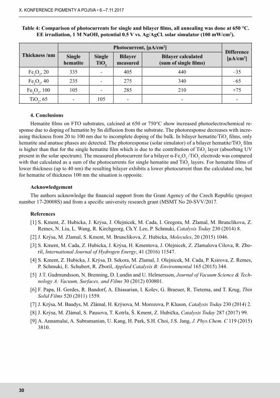
The shape of chopped polarization curves is for single hematite and bilayer hematite/TiO2 very similar. The values of photocurrent are compared in Table 4. In all cases, the photocurrent for bi-layer α-Fe2O3/TiO2 prepared by subsequent single film deposition (involving annealing) is higher than for single hematite layers. This due to the fact that the TiO2 layer itself is photoactive, i.e. absorbing light in the UV which is contained in the output of the solar simulator. The highest increase is for the bilayer consisting of hematite of thickness 100 nm, which gives the lowest photocurrent of the 20 – 40 – 100 nm series, for reasons enumerated above. Comparing the measured photocurrent for a bilayer α-Fe2O3 /TiO2 electrode with that calculated as a sum of the photocurrents for single hematite and TiO2 layers, the difference depends on the thickness of hematite. For hematite films of 20 and 40 nm the resulting bilayer exhibits a lower photocurrent than the calculated one, about 10 and 20 %, respectively, but for hematite of thickness 100 nm the situation is opposite and the resulting bilayer exhibits about 35 % higher photocurrent than that calculated. The reason for this effect is yet not entirely clear.
30
X. KONFERENCE PIGMENTY A POJIVA • 6.–7.11.2017
Table 4: Comparison of photocurrents for single and bilayer films, all annealing was done at 650 °C. EE irradiation, 1 M NaOH, potential 0.5 V vs. Ag/AgCl. solar simulator (100 mW/cm2).
Thickness /nmPhotocurrent, [µA/cm2]
Difference [µA/cm2]Single
hematiteSingle TiO2
Bilayer measured
Bilayer calculated (sum of single films)
Fe2O3, 20 335 - 405 440 –35
Fe2O3, 40 235 - 275 340 –65
Fe2O3, 100 105 - 285 210 +75
TiO2, 65 - 105 - - -
4. ConclusionsHematite films on FTO substrates, calcined at 650 or 750°C show increased photoelectrochemical re-
sponse due to doping of hematite by Sn diffusion from the substrate. The photoresponse decreases with incre-asing thickness from 20 to 100 nm due to incomplete doping of the bulk. In bilayer hematite/TiO2 films, only hematite and anatase phases are detected. The photoresponse (solar simulator) of a bilayer hematite/TiO2 film is higher than that for the single hematite film which is due to the contribution of TiO2 layer (absorbing UV present in the solar spectrum). The measured photocurrent for a bilayer α-Fe2O3 /TiO2 electrode was compared with that calculated as a sum of the photocurrents for single hematite and TiO2 layers. For hematite films of lower thickness (up to 40 nm) the resulting bilayer exhibits a lower photocurrent than the calculated one, but for hematite of thickness 100 nm the situation is opposite.
AcknowledgementThe authors acknowledge the financial support from the Grant Agency of the Czech Republic (project
number 17-20008S) and from a specific university research grant (MSMT No 20-SVV/2017.
References[1] S. Kment, Z. Hubicka, J. Krýsa, J. Olejnicek, M. Cada, I. Gregora, M. Zlamal, M. Brunclikova, Z.
Remes, N. Liu, L. Wang, R. Kirchgeorg, Ch.Y. Lee, P. Schmuki, Catalysis Today 230 (2014) 8.[2] J. Krýsa, M. Zlamal, S. Kment, M. Brunclikova, Z. Hubicka, Molecules, 20 (2015) 1046.[3] S. Kment, M. Cada, Z. Hubicka, J. Krýsa, H. Kmentova, J. Olejnicek, Z. Zlamalova Cilova, R. Zbo-
ril, International Journal of Hydrogen Energy, 41 (2016) 11547.[4] S. Kment, Z. Hubicka, J. Krýsa, D. Sekora, M. Zlamal, J. Olejnicek, M. Cada, P. Ksirova, Z. Remes,
P. Schmuki, E. Schubert, R. Zboril, Applied Catalysis B: Environmental 165 (2015) 344.[5] J.T. Gudmundsson, N. Brenning, D. Lundin and U. Helmersson, Journal of Vacuum Science & Tech-
nology A: Vacuum, Surfaces, and Films 30 (2012) 030801.[6] F. Papa, H. Gerdes, R. Bandorf, A. Ehiasarian, I. Kolev, G. Braeuer, R. Tietema, and T. Krug, Thin
Solid Films 520 (2011) 1559.[7] J. Krýsa, M. Baudys, M. Zlámal, H. Krýsova, M. Morozova, P. Kluson, Catalysis Today 230 (2014) 2.[8] J. Krýsa, M. Zlámal, S. Pausova, T. Kotrla, Š. Kment, Z. Hubička, Catalysis Today 287 (2017) 99.[9] A. Annamalai, A. Subramanian, U. Kang, H. Park, S.H. Choi, J.S. Jang, J. Phys.Chem. C 119 (2015)
3810.
31
X. CONFERENCE ON PIGMENTS AND BINDERS • 06–07/11/2017
UFI-KÓD (PŘÍLOHA VIII NAŘÍZENÍ CLP) – CO NÁS ČEKÁ?BUREŠOVÁ B.SBLCore s.r.o.
ShrnutíUFI-kód je jedinečný identifikátor složení směsí podle přílohy VIII nařízení CLP. Zahrnuje informace
o směsi, její nebezpečnosti, včetně obsažených složek, a dále informace o předkladateli, včetně telefonního čísla a emailové adresy. Tyto informace jsou dále využívány „určenými subjekty“, přičemž v České republice
je tímto subjektem Toxikologické informační středisko. Vygenerovaný UFI-kód je nutné uvádět do bezpeč-nostního listu a na etiketě směsi.
Povinnost generování UFI-kódu se týká pouze dovozců a následných uživatelů, kteří uvádějí na trh směsi, přičemž pro určitá použití jsou stanoveny různé, avšak závazné, termíny:
• od 1.1.2020 pro spotřebitelské použití,• od 1.1.2021 pro profesionální použití,• od 1.1.2024 pro průmyslové použití,
V případě, že směsi již byly oznámeny do registru CHLAP před uvedenými daty pro specifická použití, mo-hou dovozci a následní uživatelé využít přechodného období a UFI-kód vygenerovat nejpozději do 1.1.2025.
32
X. KONFERENCE PIGMENTY A POJIVA • 6.–7.11.2017
THE POSSIBILITIES OF INFORMATION SEARCHING REGARDING THE FULFILLMENT OF LEGAL OBLIGATIONS FOR SVHC AND OTHER
SUBSTANCES USED IN PAINTS, COATINGS AND BINDERSMOŽNOSTI HLEDÁNÍ INFORMACÍ Z HLEDISKA PLNĚNÍ
LEGISLATIVNÍCH POVINNOSTÍ U SVHC A JINÝCH LÁTEK POUŽÍVANÝCH V BARVÁCH, POVLACÍCH A POJIVECH
ASRESAHEGNOVÁ Z.Medistyl, spol. s r.o.
Výroba, dovoz, používání či jen pouhá distribuce chemických látek, směsí a předmětů sebou přináší spoustu legislativních povinností. V případě SVHC a jiných látek použitých v barvách, povlacích, pojivech a v podobných chemikáliích tomu není jinak a někdy je třeba vyvinout značné úsilí, aby bylo vše legislativně v pořádku. SVHC jsou látky mimořádně nebezpečné a jejich přítomnost v dodávaných výrobcích může vést k povinnosti žádat o povolení použití dané látky, povinnosti dodržovat podmínky omezení dané látky, povin-nosti oznamovat tyto látky či informovat odběratele. U ostatních látek může být nutné řešit povinnost jejich registrace nebo „jen“ zpracovat bezpečnostní list. U biocidních výrobků používaných např. ke konzervaci ba-rev platí také některé další povinnosti. Při plnění legislativních požadavků je často třeba dohledávat potřebné informace v odborných zdrojích. K tomuto účelu mohou sloužit vědecko-technické databáze v databázové síti STN. Na rozdíl od veřejně dostupných zdrojů zde lze naformulovat dotaz formou klíčových slov přesně na míru. STN v sobě zahrnuje více než 100 databází mimo jiné toxikologickou databázi RTECS nebo nejlepší databázi z oblasti chemie, Chemical Abstracts.
33
X. CONFERENCE ON PIGMENTS AND BINDERS • 06–07/11/2017
CONTROL OF SURFACE PROPERTIES OF TRANSPARENT WATERBORNE LACQUERS BASED ON ACRYLIC LATEXES
ŘÍZENÍ POVRCHOVÝCH VLASTNOSTÍ TRANSPARENTNÍCH VODOU ŘEDITELNÝCH LAKŮ NA BÁZI AKRYLÁTOVÝCH LATEXŮ
1 Ústav chemie a technologie makromolekulárních látek FCHT, Univerzita Pardubice2 Společná laboratoř chemie pevných látek Ústavu makromolekulární chemie AV ČR a Univerzity Pardubice
3 Ústav environmentálního a chemického inženýrství FChT, Univerzita Pardubice
SummaryThe use of polymeric materials as protective coatings has become an integral part of surface protection and different types of synthetic polymeric coatings have been developed. Among them, fluorinated polyacrylate latexes with special surface properties, good adhesion to matrices and especially environmental protection
value have attracted the increasing attention. It is well known that during the film-forming process of latexes with fluorine-free acrylic core and fluorine-containing acrylic shell, the shell preferentially migrates to the surface to minimize the interfacial energy and endows the materials with excellent surface properties. On the contrary, the core assembles in the bulk and provides materials with good adhesion to the substrate.
However, the fluorine groups can migrate to the inside of latex films when the environment surrounding the latex film changes, such as being immersed into water. This phenomenon leads to decrease of some proper-ties of fluorinated latex films, such as water-resistance. If the fluorinated groups are fixed on the surface of films, this problem might be resolved. In this study, core-shell latexes comprising copolymerized perfluore-thyl groups in particle shell were prepared by the semi-continuous non-seeded emulsion polymerization of 2,2,2-trifluorethyl methacrylate, methyl methacrylate, butyl acrylate and methacrylic acid as main mono-
mers. The effects of pre- and post-coalescence crosslinking on coating hydrophobicity were investigated with respect to temperature and relative humidity changes during the film-forming process. The pre-coalescence crosslinking of latex particles was achieved by copolymerizing allylmethacrylate during the synthesis. For
the post-coalescence crosslinking, diacetone acrylamide was copolymerized into the shell layer of latex particles to provide sites for subsequent reaction with adipic acid dihydrazide. The results confirmed theore-tical predictions and described empirically the effects of crosslinking, temperature and relative humidity on
hydrophobicity and water sensitivity of fluorine-containing coatings.Key words
AcknowledgementsThe Technological Agency of the Czech Republic (TE02000011) is gratefully acknowledged for sup-
porting this work.
34
X. KONFERENCE PIGMENTY A POJIVA • 6.–7.11.2017
DIGITAL SOLUTIONS FOR MEASUREMENT, COMMUNICATION AND VISUALIZATION OF MATERIAL SURFACE APPEARANCE
TAC – TOTAL APPEARANCE CAPTURE ... ZACHYŤTE MATERIÁLY S NEPŘEKONATELNÝM REALISMEM
MATUŠKOVÁ L.X-Rite Europe GmbH
SummaryAppearance of a product is a key attribute when considering purchasing the product. Control of a color
quality should therefore be an integral part of any production where color plays an important role.However, an overall look is much more than just color. It is a visual feeling we get when perceiving an object. Perception includes not only the color, but also size, structure, gloss and transparency or
opacity of the product. Traditionally, capturing and virtual rendering of material´s appearance has been time-consuming manual process. Accurate measurement of physical materials through TAC provide a digital presentation of a visual appearance without the need for manual editing. From pigments with special effects to synthetic fabrics, it is now possible to capture and communicate features of physical appearance such as
color, shine and texture, digitally capturing unrivaled realism in 3D designs.Key words
Beyond color is appearance, beyond color measurement is Total Appearance Capture.Today we’re talking about an innovative solution to a problem we’ve identified by talking to industrial
designers, visualization experts and marketers around the globe. There’s a need for speed in design, especially when it comes to time to market. Consumer preferences are more demanding than ever before and changing faster and faster. Companies that can keep up will stand out in this increasingly competitive market. But this places immense pressure on the shoulders of designers and development teams.
Traditionally, design has been a very manual process that still relies on estimations and the need to exchange physical prototypes with teams that might be scattered around the globe. One particular part of the process has been painfully slow – and that’s the ability to virtualize materials used in a product. There have been improvements and innovations over time, such as CAD tools, the Cloud and the ability to develop ren-derings through 3D printing.
But there’s still a need to take accurate physical appearance characteristics and migrate them into the digital world.
That is where our Total Appearance Capture solution comes in, also known as TAC. It’s an innovation that speeds up the process of meeting consumer expectations across a variety of industries, and as I mentioned, we developed it by talking with designers and individuals involved in the supply chain.
We believe it’s the last hurdle to fully digitize workflow and get products to market faster, so we’re thrilled to reveal it here today.
Let´s consider a typical product design workflow. This could be an automotive, but also any other indus-try will face similar challenges.
Typically it starts with a material supplier. They have to maintain large physical sample libraries of their materials. Managing these libraries is quite complex as you have to add new materials and remove materials which are no longer available. Doing this for one location is already a complex job, but managing multiple locations or libraries at a customer is really quite painful. Besides this, making a material sample available for a designer takes some time. Mailing a sample from Europe to the US takes a week before the designer can get his hands on the material. In addition, there are costs for producing the samples and the logistics around that.
By digitizing material appearance managing a digital library becomes quite easy and the information becomes instantly accessible from any design place in the world.
35
X. CONFERENCE ON PIGMENTS AND BINDERS • 06–07/11/2017
For the designer on the other hand, digital materials have the benefit that he can play with them in his CAD environment right away. Instead of looking at a small piece of fabric he can see the material on his design visualization.
To see how materials interact with each other you don’t have to build always an expensive physical prototype. You can simulate the look and interaction of materials within a virtual prototype which simulates accurately the real world. This helps with the internal communication, but also to give a feedback to the ma-terial supplier on changes and improvements.
In many industries, the marketing materials are generated in parallel to the product development. Quite often materials get recreated by 3D artists for different tools and applications. The results often vary depen-ding on the skills of the 3D artist and the complexity of the material. Quite often people waste a lot of time to create 3D materials in an artistic process and end up with different results in the configurator, the beauty shots and the commercial.
Last, but not leas, trends to bring virtual reality to the show rooms call for digital materials as well. Accurate virtual materials will also help here to create the perfect product experience.
Before I go deeper, we should talk about what “material appearance” really means. It’s much more than just color or a picture. It’s the complete perceptual experience.
• Size• Color• Texture• Gloss• OpacityCapturing these effects digitally was a challenge in the past. But that’s not the case with TAC.Now, digitization of the supply chain is as real and as accurate as possible. Let´s have a look what total appearance really means. It is a cross product of five things:Material: Composition, Physical Properties, Optical PropertiesGeometry: Size, ShapeScene: Direct/indirect lighting, Lighting color, Surround, Object proximityPerceptual Transformations: Contrast Sensitivity, Tone-mapping, Adaption, Context (it makes a diffe-
rence if you look at the object under office lighting or a daylight)Viewer: Distance & Angle (viewer or the camera who looks at the object from certain angles and distance)So, in more detail, what’s the technology behind TAC? How exactly is a material virtualized? 1. Select your material sample. In this example, we chose a basketball material. 2. Place it in the TAC Scanner where multiple cameras capture the material from a variety of angles using
different types of lighting. Then the information has to be communicated through the software which is called Pantora digital material HUB.
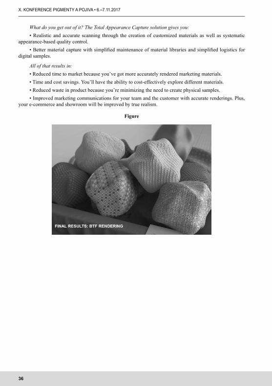
Revolutionary technology for three-dimensional scanning of complete optical properties of the sample using a multi-dimensional mathematical model BTF (Bidirectional Texture Function) respectively BRDF.
Benefits:• Ability to create databases with extremely realistic representations of any materials for their subsequent
use in design.• Capturing all the variables which are characteristic for a given material, including gloss, texture and
metallic effects. There is no need for another computer designing.• High color fidelity as well as the option to clothe a digital object with a scanned material in any shade.• Compatibility with multiangle spectrophotometer MA98 allowing to combine the scanned texture ma-
terial containing effect pigments with exact spectral characteristics as well as their specific BRDFdata.
36
X. KONFERENCE PIGMENTY A POJIVA • 6.–7.11.2017
What do you get out of it? The Total Appearance Capture solution gives you:• Realistic and accurate scanning through the creation of customized materials as well as systematic
appearance-based quality control.• Better material capture with simplified maintenance of material libraries and simplified logistics for
digital samples.
All of that results in: • Reduced time to market because you’ve got more accurately rendered marketing materials. • Time and cost savings. You’ll have the ability to cost-effectively explore different materials. • Reduced waste in product because you’re minimizing the need to create physical samples.• Improved marketing communications for your team and the customer with accurate renderings. Plus,
your e-commerce and showroom will be improved by true realism.
Figure
37
X. CONFERENCE ON PIGMENTS AND BINDERS • 06–07/11/2017
KOLORISTIKA A KOLORIMETRIE V PRAXI OPRAVÁRENSKÝCH AUTOLAKŮ
COLORISTIC AND COLORIMETRY IN REPAIR CARPAINT PRACTICE
KOŠŤÁL M.Summary
This technical text describes how can be repairs of damages to vehicle paint systems practically solved through the knowledge and tools of coloristic and colorimetry.
Key wordsColoristic, kolorimetry, repairs, vehicle, paint systems
Specifičnost oboru povrchových úprav vozidel Obor známý jako AUTOLAKY, představuje technologickou špičku povrchových úprav a má proto svá
specifika, která se promítají i do terminologie. Pro pojmenování materiálů, postupů a jevů je proto nutná nadstavba terminologie obecné, která je definována čtyřjazyčnou technickou normou ČSN EN ISO 4618 „Nátěrové hmoty – Termíny a definice“. Existuje řada osvědčených zásad, postupů a pomůcek, která školené-mu koloristovi nebo autolakýrníkovi (převážně rekvalifikovanému z jiného oboru) usnadňují zvládnutí všech situací tohoto poměrně složitého oboru.
Vybrané termíny k danému tématuTermín AUTOLAKY je nejvýstižnější zažitou zkratkou pro označení oboru povrchových úprav vozidel;
vyjadřuje specifické vlastnosti v něm se vyskytujících materiálů, technologií a jevů. Odvozenými termíny jsou AUTOLAKOVNA, AUTOLAKÝRNÍK.
Koloristika je nauka o barevných vjemech, charakteristice barev. Kolorimetrie je nauka zabývající se popisem, měřením nebo porovnáváním barevného projevu vníma-
ného světla, založeném vedle jasu zejména na spektrálním skládání vln různých vlnových délek (frekvencí) v oblasti viditelného světla. Příslušné hodnoty se zjišťují zrakem (vizuální kolorimetrie) nebo fyzikálními čísly (fyzikální kolorimetrie).
Kolorista je specialista, který se zabývá koloristikou nebo kolorimetrií (v kanceláři, laboratoři, zkušebně, autolakovně).
Etalon neboli kontrolní destička (z ocelového plechu nebo speciálního papíru) slouží k nastříkání vzorku vrchního laku a je opatřena černým pruhem nebo černobílou šachovnicí (nanášíme tolik nástřikových vrstev, až dojde k jejich zakrytí, čímž zajistíme plnou sytost barevného odstínu).
Vzorkovnice je soubor válečkovaných nebo ručně stříkaných map nebo karet (ze speciálního papíru).Světlo je viditelná část elektromagnetického záření. Člověk vidí barevné spektrum (rozsah vlnových
délek ve vakuu od 390 do 760 nm); sousední záření vnímá jako teplo (IČ-vlevo) nebo na něj jeho kůže reaguje opálením (UV záření-vpravo).
Termín barva se v oboru AUTOLAKY používá pouze pro označení primárních, sekundárních a terci-árních barev spektra. Následně se používají termíny barevný odstín (barevný kód) nebo barevný pododstín (jeho varianta). Tato kategorizace umožňuje jednodušší orientaci a zabezpečuje jednoznačnost v komunikaci vzhledem k jejich značnému množství.
Technologická vrstva (TV) nátěrové hmoty (NH) je vrstva 1 druhu NH (např. plniče), která se skládá z nástřikových (nátěrových) vrstev.
Nástřiková (nátěrová) vrstva (NV) tvoří část (výjimečně celou) technologické vrstvy. Existuje několik jejich druhů, zajišťovaných hlavně různou rychlostí posunu stříkací pistole (mokrá neboli plná, polosuchá a suchá neboli záprach; poslední dvě mají význam pouze při nanášení vrchních laků).
Koloristická vrstva NH (KV) je technologická vrstva nebo její část, která ovlivňuje finální barevný efekt (k nim patří tónovaný plnič, podstřiková vrstva vrchního laku, vrchní lak, tónovaný bezbarvý krycí lak).
38
X. KONFERENCE PIGMENTY A POJIVA • 6.–7.11.2017
Vrchní lak (VL) je technologická vrstva, která nejvýrazněji ovlivňuje finální barevný efekt, ať už tvoří finální vrstvu nebo je kryta bezbarvým krycím lakem; známe VL systému SOLID (tzv. jednovrstvé) a typu BC (tzv. dvouvrstvé).
Bezbarvý krycí lak (BKL) tvoří – pokud je použit – vždy finální vrstvu nátěrového systému. Jednou ze známek kvality BKl je jeho čirost (pokud je nažloutlý, může měnit barevný odstín a pak je potřeba provést korekturu receptury). Čím větší je tloušťka technologické vrstvy BKL, tím tmavší je výsledný barevný efekt vrchního laku.
Rozstřik je nanášení vrchního nebo bezbarvého krycího laku za pomoci speciálních přísad nebo ředidel, které je charakterizováno pozvolným přechodem nově nanášeného vrchního nebo bezbarvého krycího laku do stávajícího v místě jeho opravy („do ztracena“). Dochází přitom ke spojení uvedených technologických vrstev a pozvolnému přechodu barevného odstínu, aby tak místo opravy bylo nerozeznatelné od stávajícího okolního povrchu. Provádí se v dílu samotném nebo s přesahem do dílu vedlejšího, a to zpravidla na svislých plochách karosérie (resp. jejich svislých dílů).
Počet barevných kódů a jejich variant u opravárenských autolakůOd roku 1913 byla registrována existence cca 180 tis. barevných kódů (přičemž každý z nich má své
„jméno“) a 1,7 mil. jejich variant (to znamená v průměru téměř 9,5 variant na 1 barevný odstín). Např. k barevnému kódu (BK) ŠKODA 1001 (slonová kost) bylo podchyceno 9 variant a k nejsložitějšímu BK (PEUGEOT) existuje cca 170 variant (mnohdy výrazněji odlišných granulací, barevností a jasem). Příčiny tohoto stavu jsou různé. Výrobci autolaků pro běžné použití v praxi nabízejí na internetu cca 60 tis. aktuálních („aktivních“) receptur. Tuto databanku průběžně rozšiřují o nové barevné odstíny, přičemž nejstarší z nich současně přeřazují do receptur „pasivních“, které lze obdržet na vyžádání. Málo se vyskytující barevné od-stíny řeší autolakovny pomocí spektrofotometru s případným dotónováním nebo vytvořením individuálních receptur. Složitější případy pak s distributory výrobců autolaků.
Základní znalosti koloristy a autolakýrníkaKoloristé nebo finální autolakýrníci by měli znát posloupnost složení spektra barev, primární a sekundár-
ní barvy, základní principy míchání barev (světly-aditivní nebo pigmenty-substraktivní), identifikace barev-ných kódů a jejich variant, porovnávání shod barevných odstínů, tónování.
Technika stříkáníFinální autolakýrník musí navíc znát a zvládnout techniku nanášení nástřikových vrstev vrchního laku,
která patří k základním faktorům správného finálního barevného efektu (granulace, barevnosti, jasu). Jestliže se jednovrstvé vrchní laky SOLID u všech výrobců autolaků nanášejí ve dvou mokrých („plných“) nástři-kových vrstvách, u vrchních laků BC dva z těchto výrobců používají systém jedné polosuché, druhé mokré a třetí suché nástřikové vrstvy, která jistí konečný barevný efekt (správné položení zrn nebo eliminaci případ-ných „fleků“ u komplikovanějších receptur) vrchních laků BC; ostatní výrobci autolaků používají k nanášení i u BC-vrchních laků dvě „plné“ nástřikové vrstvy.
Technologie rozstřikuVzhledem k velikému množství vyskytujících se barevných kódů a jejich variant se považuje za úspěšné ře-
šení, když se podaří najít pro opravu vrchního laku recepturu, jejíž výsledný efekt je akceptovatelný alespoň „na rozstřik“ (viz „Vybrané termíny k danému tématu“), který se preventivně provádí i vzhledem k tomu, že autola-kýrníci v rámci své technologické disciplíny a svých dovedností v mnohých případech dosahují různých efektů.
Časté mystifikaceK mystifikacím, které se žel často zveřejňují a vnášejí do množství informací chaos, patří tvrzení, že:– smícháním 3 primárních barev vzniká černá – ve skutečnosti je to tmavě kalná hnědá barva,– na pravém kraji barevného spektra je červená primární barva – ve skutečnosti se jedná o barvu purpu-
rovou (magentu),– spektrofotometr je dokonalejší než lidské oko,
39
X. CONFERENCE ON PIGMENTS AND BINDERS • 06–07/11/2017
– receptura, kterou nabízí spektrofotometr jako nejlepší řešení (tj. s nejmenším ΔE) je pro použití nej-vhodnější; to však většinou neplatí, protože „oko“ vybere jako nejvhodnější některou recepturu z dalšího pořadí (třebas vhodnou alespoň k dotónování).
Základní parametry barevného odstínu („1+3“) a jejich priorityBarevní odstín má 3 základní parametry, které jsou členěny podle svých priorit: barevnost, tmavost/světlost,
čistota/kalnost. U metalických a perleťových barevných odstínů je před tyto parametry přiřazen další – granulace (velikost zrn), který má před výše uvedenými většinou přednost. Jaký to má praktický význam? Jestliže máme k dispozici několik receptur (ať už k nim existují ručně stříkané karty nebo autolakýrníkem nastříkané etalony), které se některým z uvedených parametrů blíží naší předloze (tj. vrchnímu laku vozidla v místě jeho opravy), vybereme si většinou ten, který se nejvíce blíží granulací (u metalických a perleťových barevných odstínů) nebo barevností (u barevných odstínů ostatních, tzv. UNI). Další parametry se dolaďují snáze.
Základní principy identifikace barevného odstínuPři porovnávání ručně stříkané karty vzorkovnice nebo etalonu s předlohou (tj. s vrchním lakem vozidla
v místě jeho opravy), musíme dbát na dodržení těchto základních zásad: – absolvovat oční test, který nám potvrdí, že naše oči mají plnou rozlišovací schopnost, – absolvovat školení koloristiky a kolorimetrie mj. i z toho důvodu, aby se naše oči staly „trénované“
a dokázali jsme v plné míře využívat jejich schopnosti,– mít oblečení barevnostně nejlépe šedé (aby při porovnávání barevných odstínů nedocházelo k jejich
zkreslení odrazem),– před porovnáváním pomocí brusné pasty a utěrky odstranit „patinu“ (nános exhalátů) a odhalit tak
původní barevnostní podobu vrchního laku,– porovnávání provádět v polostínu (vnější prostředí) nebo za pomocí simulátoru denního světla (vnitřní
prostředí),– porovnávání provádět systémem „FLIP-FLOP“ (kartu vzorkovnice nebo etalon natáčíme od vodorov-
né ke svislé poloze – zejména u metalických a perleťových vrchních laků).
Kvalita a tónování plničůKvalitní plnič zajišťuje vhodný podklad pro vrchní lak a musí být mj. přiměřeně nasákavý, aby neodsá-
val z nanášeného vrchního laku barviva (tím by mohlo dojít ke zkreslení barevného odstínu). Tónování plničů pestrými pigmenty je už historií a provádí se výjimečně (pouze v odůvodněných přípa-
dech). Tím je vyloučeno nevhodné zasahování do jejich skladby z toho vyplývající riziko možných defektů. Současným trendem je tónování nepestrými pigmenty ve škále od bílé barvy k černé přes různé stupně šedé. Existují dva systémy výrobců nátěrových hmot – řada několika předem natónovaných plničů v uvedené škále nebo si autolakýrník podle odkazu v předpisu určité receptury vrchního laku přidává černý plnič do plniče bílého. Různá stádia této škály zajišťují efektivně kryvost vrchního laku pod příslušnými úseky barevného spektra (od bílé pod purpurou barvou k černé pod barvou fialovou).
Databanky barevných kódů a receptur Výrobci autolaků mají své databanky barevných kódů a receptur vázané na:– výrobce vozidel a jejich modely,– fleetové parky vozidel (např. armádní, Coca-cola, Česká pošta …),– standardy barevných stupnic (např. RAL, PANTONE …),– ručně stříkané karty vzorkovnic.
Dva systémy koloristiky a kolorimetrieVýrobci autolaků používají dva základní systémy:– systém databanky barevných kódů, jejich variant a příslušných receptur členěný především podle vý-
robců vozidel; pro snazší orientaci je doplněn válečkovanými vzorkovnicemi a poměrně malým počtem ručně
40
X. KONFERENCE PIGMENTY A POJIVA • 6.–7.11.2017
stříkaných karet (u tohoto systému není většinou „co s čím“ srovnávat a hlavním vodítkem pak jsou pouze symboly, uvedené na jednotlivých recepturách). Tento systém je proto vhodný doplnit spektrofotometrem,
– systém databanky barevných kódů, jejich variant a příslušných receptur členěný podle výrobců vozidel a podle čísel velkého množství (cca 20 tisíc) ručně stříkaných karet, členěných na skupiny podle barevného spektra (tj. např. karty začínající osmičkou patří do oblasti červených barevných odstínů); pro rychlou orien-taci systém obsahuje také jednoduché válečkované vzorkovnice. Uvedený počet karet je potvrzením skuteč-nosti, že pigmentové báze se vyznačují stálou koloristickou kvalitou v každé jejich výrobní šarži (tj. pokud autolakýrník zvládá techniku a zručnost při nanášení vrchních laků, je zajištěna shoda receptury s příslušnou kartou). U tohoto systému nemusíme znát číslo barevného kódu, protože řešení můžeme poměrně rychle najít v např. v oddělení modrých metalických karet. Tento systém je možný kombinovat se spektrofotometrem, ale to je většinou neefektivní, protože jeho aplikací čas neušetříme. Účinnost tohoto systému je 83–93% a používá se pouze u dvou prémiových značek autolaků.
Poznámka: je paradoxní, že autolakýrníci se mnohdy přiklánějí k dodavatelům používajícím první sys-tém, protože ten druhý – i když dokonalejší – okamžitě odhaluje porušení jejich technologické disciplíny (umožňuje na dálku posuzovat, jestli autolakýrník neudělal chybu při míchání nebo nanášení VL) a vyžaduje preciznost při vyhledávání a zpětném zařazování karet do kartotéky a uchovávání jejich čistoty. Autolakýrníci převážně neradi nesou zodpovědnost a vyhovuje jim přenášet jí na distributory a výrobce autolaků.
Pomůcky koloristiky a kolorimetrieDatabanka barevných kódů a jejich variant (viz výše).Databanka receptur, na nichž jsou formou piktogramů uvedeny potřebné údaje (např. žlutá metalíza
s tendencí do oranžova, světlejší, hrubší zrno, bezolovnatá, nutné použití šedého plniče stupně v kombinaci 15% černá/bílá), které slouží k usnadnění orientace při volbě nejvhodnějších receptur pro nastříkání kontrol-ních etalonů v případech, kdy k receptuře chybí ručně stříkaná karta.
Zobrazení jednotlivých pigmentových bází ve formě map s věrným zobrazením jednotlivých aktuálních pigmentových bází jako pomůcka usnadňující tónování barevných odstínů.
Barevné kruhy s názornými návody, jak jednoduše řešit pomocí konkrétních aktuálních pigmentových bází tónování (barevnost, čistota/kalnost).
Spektrofotometry různých výrobních značek, které poskytují výrobci autolaků, jsou vybaveny přísluš-nými SW na vyhledávání standardních a tvorbu upravovaných a individuálních receptur ve vazbě na jejich aktuální sortiment pigmentových bází. Převážně se používají tří-úhlové, ale existují i 3, 5 i více-úhlové. Za-vádí se i kombinace s makro-snímky, pomocí kterých lze lépe identifikovat metalické a perleťové struktury. Jsou dobrými pomocníky, ale ať už je jejich úroveň jakákoliv, je nutné zhotovovat kontrolní etalony a hledat nejlepší řešení alespoň „na rozstřik“ – při vyhodnocování etalonů je ale konečnou instancí vždy lidské oko, pokud je prostřednictvím školení a následné praxe „trénované“ a samozřejmě pokud je bez vad, což je potřeba otestovat. Ve své dvacetipětileté praxi jsem potkal pouze jednoho autolakýrníka, jehož oči měly porušený barvocit. Ideálním řešením je kombinace spektrofotometru s rozsáhlým systémem ručně stříkaných karet, umožňující rychlá řešení a úsporu materiálu a času (není potřeba stříkat etalony).
Vzorkovnice válečkované nebo ručně stříkané.
Sortiment a kvalita pigmentových bází Důležitou složkou koloristiky a kolorimetrie je kvalita a počet pigmentových bází (PB), pomocí kterých se
formulují receptury. Tzv. prémioví výrobci autolaků, kteří jsou homologovaní pro výrobní a opravárenské lin-ky výrobců vozidel a jejich subdodavatelů nebo pro autorizované servisy, mají rozsáhlé databanky barevných kódů a jejich variant. Aby je mohli postihnout a dále aktualizovat, mají v sortimentu potřebný počet pigmento-vých bází, který se pro povrchové úpravy osobních vozidel pohybuje min. kolem 110 (z toho cca 29 pro vrchní laky SOLID a 83 pro vrchní laky BC, z toho 23 speciálních perleťových bází pro extrémní barevné odstíny). Např. vrchní metalické laky, které aplikovaly nebo aplikují výrobci automobilů s využitím cca 150 velikostí a tvarů metalických zrn, výrobci opravárenských autolaků imitují pomocí osmi velikostí zrn (obdélníkového a čočkovitého tvaru).
Známkou kvality je, že zdravotně a ekologicky šetrnější bezolovnaté pigmentové báze, které nahradily kryvější olovnaté, mají dobrou kryvost ve prospěch materiálových a časových úspor.
41
X. CONFERENCE ON PIGMENTS AND BINDERS • 06–07/11/2017
Dalším faktorem kvality je, že systém obsahuje u primárních barev dvojice pigmentových bází (koncent-rované a dekoncentrované), které umožňují míchat vrchní laky převážně už od 0,1 litru a také v případě potřeby receptury snadněji tónovat. Pokud tato dualita v systému chybí, je minimální míchané množství mnohdy až od 0,5 litru, což vede k tomu, že autolakýrník malá poškození neopravuje systémem SPOT, ale zbytečně přestříkává celý díl nebo dokonce dílů více a nemalá část zbytkových vrchních laků jde do likvidace nebo na fušky. Promítá se to pak zbytečně do peněženek zákazníků, ekonomiky autolakoven, pracovního prostředí a ekologie.
Pokud v systému jsou speciální perleťové báze, je možné po malých množstvích míchat i extrémní ba-revné odstíny, které se dosahují mj. i pětivrstvé syntetické pigmenty o velikosti 0,1 µm, které doplňují klasické pigmenty perleťové. Pokud v systému tyto pigmentové báze chybí, autolakovna si musí kupovat poměrně drahé hotové namíchané vrchní laky v balení 0,5 až 1 litr,(opět ke svému neprospěchu)
Problematika obměn pigmentových bází U výrobců autolaků dochází občas ke změnám v sortimentu pigmentových bází, které se používají
k míchání receptur vrchních laků (ať už jsou umístěny v míchacích zařízeních nebo v regálech). Vedou je k tomu různé důvody (např. změna dodavatelů, náhrada za vyšší kvalitu, tvorba nových složitějších receptur). S tím souvisí i nutnost změn receptur, které vyvolávají odchylky od receptur původních – zejména, když jich je nutno najednou změnit více (není dostatek času na kontrolu a doladění v konfrontaci s etalony receptur, které byly přepočteny prostřednictvím spektrofotometrů). Citlivé je to hlavně u systémů vázaných na ručně stříkané karty vzorkovnic a vyvolává to nutnost jejich dolaďování (zde je totiž u všech autolakoven možné „co s čím“ porovnávat).
TónováníExistují případy, ve kterých je potřeba recepturu tónovat přímo ve zkušebně distributora nebo přímo
v autolakovně. Složité případy je však potřeba řešit přímo s koloristickými laboratořemi výrobců autolaků (podle dodaných vzorků, převážně dílů karosérie-např. z nich vystřižených částí, víček nádrží PHM).
Pokud technologický systém obsahuje duální pigmentové báze (koncentrované/dekoncentrované), je tó-nování snazší (ubírám/přidávám více dekoncentrovaných kapek PB). Navíc dovoluje míchání vrchních laků v minimálních množstvích (už od 0,1 litru).
Základní zásady tónování:– používáme veškeré pomůcky koloristiky,– nejprve si provedeme jednoduchou analýzu receptury, kterou chceme upravovat (např. černá/bílá, čer-
vená/žlutá=oranžová, hrubé metalické zrno),– při úpravě konkrétní receptury pracujeme pouze s pigmentovými bázemi v ní obsaženými (přidáváme/
ubíráme),– světlost/tmavost upravujeme pomocí ubírání/přidávání pigmentových bází bílé/černé (mimo červe-
ných barevných odstínů, kde tuto funkci plní PB červené); v některých případech i pomocí ubírání/přidávání metalických nebo perleťových PB,
– barevnost nebo čistotu/kalnost upravujeme ubíráním/přidáváním příslušných pigmentových bází podle schématu na barevném kruhu.
ZávěrZ výše uvedených informací je zřejmé, že:– technologie autolaků na cestě svého historického vývoje našly řadu osvědčených postupů ke kvalitním
opravám poškození nebo defektů vrchních laků,– efektivnost opravy poškození nebo defektů vrchních laků lze provádět s různými stupni efektivity
(spotřeby času, energií a materiálu).Další podrobnosti budou zřejmé při PP-prezentaci na konferenci doplněné barevnými vyobrazeními
nebo v rámci případné diskuze.
42
X. KONFERENCE PIGMENTY A POJIVA • 6.–7.11.2017
MECHANICAL AND ANTICORROSION PROPERTIES OF ORGANIC COATINGS CONTAINING SURFACE-TREATED TALC PARTICLES
DEPENDING ON THE DOPANT TYPEMECHANICKÉ A ANTIKOROZNÍ VLASTNOSTI ORGANICKÝCH POVLAKŮ OBSAHUJÍCÍ POVRCHOVĚ UPRAVENÉ ČÁSTICE MASTKU V ZÁVISLOSTI
NA TYPU DOPANTU
NECHVÍLOVÁ K., KALENDOVÁ A.University of Pardubice, Faculty of Chemical Technology, Dep. of Organic coatings and paints,
Studentská 95, 523 10 Pardubice
SummaryBased on previous reaserch (K. Nechvilova, A. Kalendova, The investigation properties of diethyl phosphite in polyaniline base, pp. 88–92; The 8th CONFERENCE ON PIGMENTS AND BINDERS, November 2–3, 2015 Congress hotel Jezerka, Seč, Czech Republic), presented work is focused on surface-treated pigment base on laminated silica conductive polymer (PANI). H3PO4 was used as a primer dopant of PANI chain, diethyl phosphite (DEPH) was used as a secondary dopant which served for reprotonation of PANI salt.
PANI surface layer improved paint film adhesion, physico-mechanical and anticorrosion properties of orga-nic coatings. Talc particles were coated by conductive polymer on 10, 20 and 30 wt%. Epoxy-ester resin was
used as a binder. Surface-treated pigments were then applied into this resin on 1, 5 and 10 vol% concentration. These basic coatings were applied on glass and steel panels where physico-mechanical destruction tests were made by standard. Corrosion properties were afterwards tested in an industrial
enviroment containing sulfur dioxide and 100% relative humidity for 504 hours. Corrosion defects were eva-luated by ASTM standards after exposition: blistering, corrosion under the paint. The result of the work was to find the most effective paint film based on mass and volume filling with a conductive polymer depending on the type of dopant the resultant organic coating was not allowed to lose adhesion after wetting, it had to
prevent blistering and corrosion penetration of the metal substrate.Key words
IntroductionSurface protection of steel and steel products against corrosion from the surrounding environment is
a prerequisite for efficient use of the material [1]. The share of atmospheric corrosion in the factors contribu-ting to steel degradation is over 80 percent. Among feasible methods to protect steel materials from corrosion is providing the material with an organic coating containing anticorrosion pigments [2]. Such coatings are under constant supervision by health protection authorities because the pigments may be toxic and/or poten-tially harmful. With a view to avoiding such hazardous anticorrosion pigments, some scientists have been focussing on conductive polymers as organic coating ingredients imparting the paints anticorrosion properties [3]. Good anticorrosion provisions can suppress corrosion or prevent it altogether, thereby reducing the cost of repair/replacement of the corroded materials [4].
The conductivity of polymeric materials is a result of a chain of partial processes. In conductive poly-mers, adjacent carbons that are present in the sp2 hybridized state are interconnected by sharing one valence electron in the centre of the bond in the pz orbital. All the pz orbitals are interconnected to form a molecule in which the delocalized orbitals alternate periodically. Electrons in the delocalized orbitals exhibit a high mobi-lity, and if the material is doped by using an oxidative reaction, some of the electrons start moving. The conju-gated p-orbitals give rise to a one-dimensional electronic band in which the electrons are mobile provided that the orbital is partly empty. An inorganic or organic acid can serve as the dopant. Conductive polymers are not conductors in the sense attached to inorganic conductors. Actually, the term semiconductors would be more appropriate. The conductivity of the undoped conjugated polymers is very low, 10–10 to 10–8 S/cm [5]. They include, e.g. cis-polyacetylene, polythiophenes, polyethylene and the polyaniline base. Each doping level increases the electrical conductivity by 0.1 S/cm. Fully doped, some materials might attain conductivities as
43
X. CONFERENCE ON PIGMENTS AND BINDERS • 06–07/11/2017
high as 10 kS/cm. Conductivity is a property that is responsible not only for the material’s physical properties but also for its chemical properties [6–11]. A correlation has been established between the electrical conducti-vities of reprotonated bases and the pH level of the protonation medium. A high acidity (pH<1) is required for efficient reprotonation, i.e. for attaining conductivities higher than 10–2 S/cm. Negligible or nil conductivity increase (<10–8 S/cm) has been found for media with pH>3. Where strong acids are involved, the conductivity often decreases at high acid concentrations despite the high acidity (pH<0). This is so because protonation of the secondary amine groups on the polyaniline (PANI) chain as well as of the imine nitrogens takes place, whereby the electrical conductivity is adversely affected, presumably due to a reduction in the number of conjugated bonds in the chain or due to generation of polaronic charge carriers [12, 13].
Diethyl phosphite is the diester of phosphonic acid. This acid dissociates only to the second degree in aqueous solutions [14]. Diethyl phosphite is a novel, unexplored material in the domain of paints, its use with PANI as a secondary dopant has not been described so far. Interactions between this diester and PANI have been studied by Šeděnková et al., who pointed to the fact that no proton capable of providing direct interac-tion with the PANI chain exists in diethyl phosphite. In fact, the phosphite molecule is bonded to the PANI segments through P∙∙∙HN and POH∙∙∙N hydrogen bonds. Although the acid hydrogen atom in the phosphite OH group is not completely transferred to the imine nitrogen in PANI, the POH∙∙∙N distance being 1.81 Å, the PANI salt can be considered partly protonated. This is borne out by the fact that the (P)O-H covalent bond is weaker and longer (1.00 Å) here than in the isolated phosphite molecule (0.97 Å) [15].
Experimental
Surface treatment silica pigment by polyanilinePolyaniline salt was prepared by standard oxidation of 0.2M aniline phosphate with 0.25M ammonium
peroxodisulphate in an aqueous medium at room temperature. Than silicate powder was added in volume to be obtained surface layer on 20 wt.% and 30 wt.%. The reaction was accompanied by colour changes, from dark blue to the final dark (emerald) green. The final substance was filtered out, rinsed with acetone and dried in air than in dryer (60 °C). The surface layer was checked by DTA analysis (heating 5 °C/min). This was designation as primary doping. The solids were subsequently converted to polyaniline base in 1 M ammonium hydroxide, and dried at room temperature in air and then over silica gel. The PANI base was suspended in diethyl phosphite without using any organic diluent or water. After 24 hours, the solids were collected on a filter, washed with ethanol, and dried in air, and then over silica gel. This was designation as secondary doping.
Sample markingTalc pigment stands on the first place (except anticorrosion pigment diethyl phosphite which was pre-
pared by secondary doing). It follows polyaniline chain (PANI) and a type of dopant. H3PO4 is primary do-pant; diethyl phosphite is secondary dopant. PANI chain and dopant are divided by a dash “ – “.The weight coverage is shown at the last position in the formula. Generic formula: Talc/PANI-dopant-percent by weight of coverage.
Characterization of pigment powdersThe basic pigment properties were determined pycnometrically (CSN ISO 787-10). The critical pigment
volume concentration (CPVC) was determined via linseed oil consumption per 100 g of the pigment (CSN ISO 787-5) by the pestle-and-mortar method as per CSN 67 0531. The CPVC value served to set up a concen-tration series. Silicates/PANI pigment particle morphology and shapes were examined on a LYRA3 TESCAN (Czech Republic) electron microscope. Matter soluble in hot water (W100) and in cold water (W20) was also determined per CSN EN ISO 787-3 and 787-8, respectively. The pH and specific electric conductivities (χ) of a 10% aqueous extract of the pigment powder were measured during 28 days as per CSN EN ISO 789-9 and CSN EN ISO 787-14. The suspension was filtered, and a clean and pre-weighed steel panel was submerged in the filtrate for 10 days, after which the panel was removed from the extract and the corrosion loss (Km) was measured.
Paint formulation and preparationThe paint systems were formulated on computer program FORMUL. As a binder was used epoxy-ester
resin on solvent-type (WorléeDur D46, Worlée Chemie, Germany). The model paints were prepared by adding
44
X. KONFERENCE PIGMENTY A POJIVA • 6.–7.11.2017
the pigment to the binder and homogenizing the system. The pigment volume concentration (PVC) in the paint was 1 % and 10 %. The paints were pre-prepared on a dissolver and dispersed in a laboratory bead mill at 3000 rpm for 45 minutes. Before applying to panels, Nuodex Combi (mix of salts Co/Ca/Zr from Huntsman, Germany) was added at 0.1 wt.% as a siccative Than the paints were applied to glass and low-carbon steel panels where physico-mechanical tests were done.
Characterization of paint films by physico-mechanical testsThe physico-mechanical properties of the paint films were determined by subjecting the films to mecha-
nical and destructive stress according to ISO standards 2409, 6272, 1519, and 1520.
Determination of resistance to humid atmospheres containing sulphur dioxide (ISO 3231)The corrosion test was performed on steel panels 150 mm x 100 mm x 0.9 mm size, coated with the paint
films. A test cut 8 cm long was made through each paint film as per EN ISO 12944-6 by cutting tool (ISO 2409). The samples were exposed to the sulphur dioxide mist with 100% condensed moisture environment during 504 hours, and the corrosion effects were evaluated as per EN ISO 4628-2 to 4628-5 after terminating the exposure. The parameters measured included blistering on the paint film surface (ASTM D 714-78), degree of metal corrosion on the test cut (ASTM D 1654-92) and degree of corrosion of the metal surface (ASTM D 610-85).
Results Tables 1 and 2 show the characterization of pigment powders and the coating films prepared therefrom,
which have been evaluated according to the respective standards. Figure 1 illustrates the thermogravimetric measurement performed for the total determination of the organic fraction in the pigment mixture. The SEM images in Figures 2a and 2b illustrate the real shape and coverage of the particles of talc with the conductive polymer layer.
DiscussionThe physico-mechanical and anticorrosion properties of the powdered pigments synthesized and of the
paint films containing them were measured in dependence on the pigment volume concentration (PVC), on the weight fraction of talc coating with the conductive polymer and on the doping type. When talc was used, only the barrier mechanism of substrate metal protection played a role and the highest anticorrosion efficiency sco-re in an SO2 environment (ESO2
) at the optimum PVC = 10% was 81 on the 0–100 scale: the corroded fraction of the metal substrate area was 1%, corrosion in the test cut was 1 mm, the paint film blistering score was 8F and the test cut blistering score was 8M. While the ESO2
score was the same if diethyl phosphite (PANI-DEPH) was used as the anticorrosion pigment, no blistering occurred in the test cut, the metal surface corroded frac-tion was higher, viz. 16%, and corrosion in the test cut was mere 0.3 mm.
The aim of the present work was to combine the two materials into a single coating system so as to increase the ESO2
score. This intention was also compared with respect to the conductive polymer (PANI salt) content on the silicate particle surface, i.e. the weight coverage.
When secondary doping with diethyl phosphite was used instead of primary doping with phosphoric acid, the oil number per 100 g of pigment and hence, the density, were lower (Table 1). This implied a smal-ler specific surface area of the emerging pigment particle, thus hindering adsorption of substances from the surrounding corrosion environment of SO2 that might penetrate along the surface of the particles as far as the substrate metal. This fact brought about favourable reduction of the degree of metal substrate corrosion from 16% to 0.1–0.01%. In order to minimize the steel panel surface corrosion, the pH of aqueous extracts of the pigment powders had to lie near the neutral region, with an electrode potential about –700 mV. At that moment, the barrier mechanism of protection was augmented with the steel substrate cathode protection mechanism, which had initially been present in the acid pH region. Adequate reduction of the emeraldine salt to leukoemeraldine, with the co-existence of the anionic dopant of the PANI chain which then formed a Fe(OH)3/Fe2O3 mixture, occurred even at a low PANI salt content in the system. Such substances are capable of forming complex compounds with PANI, to fill any pores in the paint film and prevent penetration of the additional corrosive medium to the substrate. In an environment with SO2, low-pH sites would form due to the presence of sulphuric acid which would promote substrate metal corrosion. Based on the W20 and W100
45
X. CONFERENCE ON PIGMENTS AND BINDERS • 06–07/11/2017
Table 1: Characterization of pigment powders and paint films
a) Critical pigment volume concentration calculated by linseed oil consumptionb) Conductivity value of the powder pigments in aqueous extracts, in 28 daysc) pH value of the powder pigments/paint films in aqueous extracts, in 28 days
d) Determination of water soluble matter for pigments (CSN EN ISO 787-3 and 787-8)e) Corrosion losses of steel panels submerged in aqueous extracts of the free paint films, in 38 days
Figure 1: The thermogravimetric curves of surface treatment talc pigment
46
X. KONFERENCE PIGMENTY A POJIVA • 6.–7.11.2017
data, the Talc/PANI-DEPH system (secondary dopant) was more stable and temperature changes did not bring about so appreciable disproportionation or deprotonation of the PANI chain. Also, the metal weight loss per unit area is 1/3 to 1/4 that observed with the Talc/PANI-H3PO4 system as in the case of primary doping. The metal weight loss was one-half that observed with the DEPH pigment. Secondary surface treatment of the talc was beneficial as regards the total quantity and rate of the extracted dopants in the aqueous system. By contrast, Talc/PANI-H3PO4 as the primary dopant exhibited a higher ion mobility and electron exchange in the aqueous system, due to which the weight loss per unit steel surface area was higher. On the other hand, though, they contributed to the corrosion protection of the substrate metal. This protection was rather efficient from the short-time perspective but not from the long-time perspective because in the long run, “oversaturation” (“cho-king”) of the system took place and the system degraded on its own due to excessive electron exchange. The primary dopant conductivity was at the level of 10–1 at pH 1.89. Secondary doping with PANI-DEPH brought about conductivity reduction to 10–3 at pH 2.65 (Day 28). Surface treatment with the Talc/PANI-H3PO4 system preserved the conductivity 10–1 while increasing the pH to 2.2. Secondary doping with Talc/PANI-DEPH also preserved the conductivity level (conductivity remained unaffected by talc) but pH increased to 4.5 (depen-ding on the weight coverage type). The organic component content of the pigment system was determined by TGA, providing the total polyaniline fraction in weight percent (Fig. 1). The particle shapes and surface patterns were examined on an electron microscope (Figs 2a and 2b).
Table 2: Corrosion in the SO2 containing chamber after 504 hours
Composition of the PAINT FILMS PVC
[%]
Blistering CorrosionAdhesion
[dg.] ESO2f)
Pigment/PANI-dopant-wt.% area[dg.]
test cut[dg.]
area[%]
test cut[mm]
Talc 10 8M 8F 1 1 0 81
PANI-DEPH 10 6F - 16 0.3 0 81
Talc/PANI-H3PO4-10wt.% 10 8F - 0.3 0.5–1 0 92
Talc/PANI-H3PO4-20wt.% 10 8M - 0.03 1.0–1.5 1 84
Talc/PANI-H3PO4-30wt.% 1 6M - 0.03 0.5–1 0 89
Talc/PANI-DEPH-10wt.% 10 6MD - 0.01 1 0 82
Talc/PANI-DEPH-20wt.% 5 8M - 0.01 0.5 0 86
Talc/PANI-DEPH-30wt.% 10 8M - 0.01 0.3–0.5 0 90
f) Anticorrosion efficiency of industrial atmosphere – arithmetic average of the evaluation numbers
X. CONFERENCE ON PIGMENTS AND BINDERS • 06–07/11/2017
Where the surface treatment was examined with respect to the weight coverage parameter, the lowest oil number was observed for Talc/PANI-H3PO4-10wt.% and was found to increase with increasing amount of the conductive polymer on the particle surface. The same patterns were observed for the critical pigment volume concentration (CPVC). The lowest filling was possible for the lowest weight filling (10 wt.%), which also atta-ined the highest ESO2
score (92), whereby it became the most efficient combination of the substances tested for the primary dopant. No blisters occurred on the paint film at PVC = 10 % and they were classed 8F in the test cut with respect to their size and number. Only the extent of corrosion in the cut was 0.5–1 mm (Table 2). The issue of a higher occurrence of corrosion in the cut did not exist with the Talc/PANI-H3PO4-30wt.% system at PVC = 1 %. Larger blisters, however, were present (6M). The oil numbers were higher, and poorer paint film adhesion to the steel substrate was feasible. Therefore, the PANI-DEPH secondary dopant was examined. This dopant exhibits opposite trends. The density and oil number decreased with increasing weight filling. Those physical properties of the PANI-DEPH-based pigments were mirrored in the resulting CPVC level, where the overall system had to be filled to lower values. The Talc/PANI-DEPH-30wt.% system at PVC = 10 % provided the best results. Its ESO2
score was 90, the corrosion reduction in the cut to 0.3–0.5 mm being the most marked feature. Secondary doping with PANI-DEPH was used owing to its outstanding adhesion, as was the case with phosphoric acid as the primary dopant. Rather than complex bond formation, adhesion occurred through a host of hydrogen bonds between a phosphite molecule and the PANI chain. Secondary doping brought about a synergistic effect of the silicate pigment talc, residual primary phosphoric acid, partial back-transition to the polyaniline base and the action of the diethyl phosphite itself.
ConclusionThis work used talc, a common filler, as a carrier silicate matrix to adsorb a partial layer of the conductive
polymer. The initial anticorrosion properties of talc were improved by the newly synthesized polyaniline salt. The anticorrosion efficiency score (0–100) increased to above 90: the effect of the primary dopant, phosphoric acid (PANI-H3PO4), brought about decrease in the number and size of blisters on the paint film surface and elimination of blisters from the test cut. The secondary dopant, diethyl phosphite (PANI-DEPH), contributed additional corrosion reduction in the test cut. A suitably formulated paint system with Talc/PANI-DEPH--30wt.% in an epoxy-ester resin at PVC = 10 %, completed with an inert filler of the CaCO3 type, may be used to completely protect a steel panel from a corrosive medium including SO2 fog.
AcknowledgementThe authors thank the Canter for Materials and Nanotechnologies (CEMNAT) for electron microscope
images in project ED4.100 / 11.0251.
References[1] P. P. Deshpande, N. G. Jadhav, V. J. Gelling, D. Sazou, Conducting polymers for corrosion protection:
A review, J. Coatings Technol. Res., 2014, 11 (4), p473–494.[2] E. Armelin, R. Pla, F. Liesa, X. Ramis, J. I. Iribarren, C. Alemán, Corrosion protection with polyani-
line and polypyrrole as anticorrosive additives for epoxy paint, Corros. Sci., 2008, 50 (3), p721–728.[3] X. Yang, B. Li, H. Wang, B. Hou, Anticorrosion performance of polyaniline nanostructures on mild
steel, Prog. Org. Coatings, 2010, 69 (3), p267–271.[4] G. Ebrahimi, F. Rezaei, J. Neshati, Investigation on corrosion protection mechanism of polyaniline
nanoparticles doped with phosphoric acid by scanning Kelvin probe and other electrochemical met-hods, J. Taiwan Inst. Chem. Eng., 2017, 70, p 427–436.
[5] J. Prokeš, J. Stejskal, and M. Omastová, “Polyanilin a polypyrrol - dva představitelé vodivých poly-merů,” Chem. List., 2001, 95 (8), p484–492.
[6] H. Sirringhaus, Device physics of solution-processed organic field-effect transistors, Adv. Mater., 2005, 17 (20), p2411–2425.
[7] D. J. Lipomi, J. A. Lee, M. Vosgueritchian, B. C.-K. Tee, J. A. Bolander, Z. Bao, Electronic properties of transparent conductive films of PEDOT:PSS on stretchable substrates, Chem. Mater., 2012, 24 (2), p373–382.
48
X. KONFERENCE PIGMENTY A POJIVA • 6.–7.11.2017
[8] V. Vijay, A. D. Rao, K. S. Narayan, In situ studies of strain dependent transport properties of con-ducting polymers on elastomeric substrates, J. Appl. Phys., 2011, 109 (8), p084525-084525-6.
[9] C. S. Yannoni, T. C. Clarke, Molecular Geometry of cis - and trans -Polyacetylene by Nutation NMR Spectroscopy, Phys. Rev. Lett., 1983, 51 (13), p1191–1193.
[10] F. Sariciftci, N S; Smilowitz, L Heeger, Alan J., Wudl, Photoinduced electron transfer from a con-ducting polymer to buckminsterfullerene, Science, 1992, 258 (5087), p1474–1476.
[11] W.-P. Heeger, A. J. Kivelson, S. Schrieffer, J. R. Su, Solitons in conducting polymers, Rev. Mod. Phys., 1988, 60 (3), p781–850.
[12] J. Stejskal, J. Prokeš, M. Trchová, Reprotonation of polyaniline: A route to various conducting polymer materials, React. Funct. Polym., 2008, 68 (9), p1355–1361.
[13] F. X. Perrin, C. Oueiny, Polyaniline thermoset blends and composites, React. Funct. Polym.,2017, 114, p 86–103.
[14] A. Sood, C. K. Sood, I. H. Hall, B. F. Spielvogel, Boron analogues of phosphonoacetates synthesis, characterization and antitumor properties of sodium diethylphosphite-carboxyborane and related compounds, Tetrahedron, 1991, 47 (34), p6915–6930.
[15] I. Šeděnková, M. Trchová, J. Dybal, J. Stejskal, Interaction of polyaniline film with dibutyl phospho-nate versus phosphite: Enhanced thermal stability, Polym. Degrad. Stab., 2016, 134, p357–365.
49
X. CONFERENCE ON PIGMENTS AND BINDERS • 06–07/11/2017
THE INFLUENCE OF POLYANILINE BENZOATE ON THE CORROSION INHIBITION EFFICIENCY OF ZINC-FILLED ORGANIC COATINGS
VLIV POLYANILIN BENZOÁTU NA KOROZNĚ INHIBIČNÍ ÚČINNOST ZINKEM PLNĚNÝCH ORGANICKÝCH POVLAKŮ
KOHL M., KALENDOVÁ A.Faculty of Chemical Technology, Institute of Chemistry and Technology of Macromolecular Materials,
University of Pardubice, Studentská 95, 53210 Pardubice, Czech Republic.
SummaryThe aim of this work was to evaluate the effect of polyaniline benzoate on the corrosion inhibiting efficiency of organic coatings pigmented with zinc. For this, polyaniline benzoate was synthesized and, together with the zinc, characterised. The parameters whose knowledge is necessary for an appropriate formulation of the pigmented organic coatings were determined. Epoxy-ester resin-based paints containing the pigments
examined were then formulated and applied to steel panels. The paint films' physico-mechanical resistance was tested by standardised methods to determine their adhesion, elasticity and flexibility. Furthermore, the
organic coatings' anticorrosion efficiency was assessed by the cyclic corrosion test in a neutral salt fog atmosphere and in an SO2-containing atmosphere. The highest mechanical and anticorrosion resistance was attained with the organic coating containing the pigment (i.e. polyaniline benzoate) at a volume concentra-
IntroductionOrganic coatings pigmented with zinc dust are used mainly owing to the zinc's ability to act as a "sacrifi-
ced" electrode in the system. This, however, requires zinc to be present at a high volume concentration [3, 4], ensuring electrical contact between the zinc particles themselves and between the zinc particles and the subs-trate metal being protected. In contact with a corrosive medium, such coatings provide first what is referred to as cathodic protection, during which the zinc corrosion products fill the coating's pores, make them leaktight and reduce the protective coating's conductivity. As a result of this conductivity reduction, the electrochemi-cal protective mechanism is transformed into the barrier mechanism. This is active protection, because the electrochemical cathodic protection mechanism is restored if the coating is disturbed [4–7]. Stringer and strin-ger standards governing the use of zinc-pigmented organic coatings are being adopted. Also, high-zinc coa-tings are not very resistant to mechanical damage, and zinc sedimentation in the binder due to its high density poses a problem when storing the pigmented paints [8, 9]. For those and other reasons, approaches aimed to reduce the zinc content in the coatings are currently studied. The use of conductive polymers is an option [10].
A number of papers describe the potential of conductive polymers in steel protection against corrosion. Among potential conductive polymers, polyaniline (PANI), specifically its conductive species (emeraldine salt), is being studied most extensively [10, 11].
Studies have shown that emeraldine salt of PANI is able to protect steel by stabilizing the potential of iron in passive region by forming protective passive layer. Other studies have provided direct information on the redox process occurring in the PANI coatings. Other studies have shown that the formation of iron-dopant complex also passivates steel [12]. The effect of the dopant type has also been examined by using phosphoric acid, hydrochloric acid and sulphonic acid. The dopant type has been found to affect the anticorrosion pro-perties of the protective organic coatings pigmented with the polyaniline salt. Since benzoate is a good iron corrosion inhibitor, polyaniline benzoate was prepared in the present work and used as the pigment in the organic coatings tested [13, 14].
Experimental part
Preparation of polyaniline benzoate
50
X. KONFERENCE PIGMENTY A POJIVA • 6.–7.11.2017
Polyaniline was obtained by oxidative polymerization of aniline in H3PO4 using ammonium peroxodi-sulphate. The synthesized polyaniline was dedoped by dispersing and stirring in 1 M NH4OH for 12 h. The dedoped polyaniline was filtered and dried. Redoping of polyaniline was made by dispersing the polyaniline to dilute benzoic acid and stirring for 12 h. The polyaniline benzoate (PANI-BENZ) was filtered and washed with distilled water and dried in oven at 60 °C for 2 h.
Specification of the pigments2 % suspension of the polyaniline benzoate in redistilled water was then prepared and values of pH and
conductivity were followed for 28 days. The critical pigment volume concentration (CPVC) of the pigments was calculated from the density determined using Autopycnometer Micromeritics 1320 and oil absorption was determined according to the Czech State Standard (CSN) 67 0531 using the "pestle – mortar" method. Parameters are given as arithmetic averages within 10 measured values. Determination of particle size and the distribution of pigment particle size were identified by means of Mastersizer 2000 (Malvern, Instruments Ltd., UK) that is able to measure the distribution of particles sized from 0.01 to 2000 μm.
Formulation and preparation of organic coatingsThe description binder WorléeDur D 46, is a short oil epoxy ester based on conjugated drying fatty
acids. It is used in air-drying and stoving finishes with outstanding adhesion, rapid drying and good chemical resistance. Organic coatings were prepared by combining zinc metal with polyaniline benzoate, using the pigment volume concentrations (PVC) 1, 5, 10, 15 % and zinc metal volume concentration (PVC) 67 %. To compare the results obtained with polyaniline benzoate an organic coating containing only zinc metal (at PVC = 67 %) was prepared. Organic coatings were dispersed using a Dissolver-type equipment at 3000 rpm for 30 minutes. Once prepared, the paints were applied to steel panels (standard S-36 low-carbon steel panels, Q-Lab Corporation) and the dry film thickness (DFT) was measured with a magnetic gauge as per ISO 2808. An artificial vertical cut was made through the paint films for the accelerated corrosion tests. The vertical test cut in the organic coating was 80 mm long and 0.5 mm deep and was made in accordance with CSN EN ISO 12944–6 by using a cutting tool complying with ISO 2409 (tool for single cuts).
Mechanical properties of the paints The paints were subjected to tests providing information on the paint film elasticity and strength.
Adhesion of the films to the substrate was assessed on cutting a lattice into the films as per ISO 2409, by using a special cutting blade with cutting edges 2 mm apart. The impact strength of the paint films applied to steel panels was determined by letting a 1000 g weight fall onto the panels from different heights and recording the largest height (in mm) at which the film integrity remained undisturbed (ISO 6272). The paint film re-sistance to cupping was evaluated by measurement on an Erichsen cupping tester. The result is the steel ball indentation depth (in mm) at which the film integrity remained undisturbed, as specified in ISO 1520. The test aimed at evaluating the paint film resistance to bending consists in bending the painted panels over mandrels of different diameter and recording the largest diameter (in mm) at which the paint film integrity is disturbed, as specified in ISO 1519.
Corrosion test proceduresThe steel panels coated with the organic coatings were subjected to accelerated cyclic corrosion tests in
2 different environments. In an NaCl spray atmosphere with steam condensation (ISO 9227), to which the panels were exposed for 720 hours; in an SO2 atmosphere with water condensation (ISO 6988), to which the panels were exposed for 1440 hours.
The degree of blistering on the surface of the coatings (ASTM D 714-78), the degree of corrosion at the test scribe (ASTM D 1654-92) and the degree of steel surface corrosion (ASTM D 610-85) were evaluated after the exposure in the corrosive environments.
Results and discussion
Pigment specificationThe basic characteristics of polyaniline benzoate and zinc are listed in Table 1. The critical pigment
volume concentrations (CPVC) of the two pigments were calculated from the density and oil absorption
51
X. CONFERENCE ON PIGMENTS AND BINDERS • 06–07/11/2017
data. Knowledge of the CPVC is a prerequisite for good formulation of the pigmented organic coating. Aqueous 2% (w/w) suspensions of the pigments were prepared in redistilled water pH 6.50 ± 0.01, con-ductivity 1.5 μS.cm–1, and their pH and conductivities were measured in 28 days. The polyaniline benzoate suspension exhibited a pronounced pH decrease to 2.25 and conductivity increase to 15.7 mS/cm, which is explained in terms of a mechanism based on polyaniline benzoate deprotonation [15]. No appreciable pH or conductivity change was observed in the zinc suspension.
Table 1: Characteristics of the pigments
Sample Density[g/cm3]
Oil absor.[g/100g]
CPVC[%] pH28 Conductivity28
[mS/cm]Particle size
d50 [µm]
Zinc 7.14 6,4 67 6,58 3,1×10⁻³ 5.20
PANI-BENZ 1,31 53,5 57 2.25 15.7 4.81
Results of the mechanical properties of the protective organic coatingsThe organic coatings' physico-mechanical resistance was tested by standardised methods to determine
the adhesion, elasticity and flexibility of the paint films. The results, listed in Table 2, demonstrate that the coatings containing polyaniline benzoate exhibit a higher mechanical resistance than the reference coating containing zinc solely. And the resistance of the coatings to the cupping test increased with increasing polya-niline benzoate volume concentration in the system.
Table 2: Results of the mechanical properties of the organic coatings containing polyaniline benzoate together with zinc metal, DFT = 60 ± 10 µm
PVCPANI-BENZ.[%]
Adhesion test[dg]
Bend test[mm]
Impact test[cm]
Cupping test[mm]
0 2 < 6 95 3,90
1 1 < 4 > 100 4,22
5 1 < 4 > 100 4,46
10 1 < 4 > 100 4,84
15 1 < 4 > 100 5,28
Evaluation of accelerated corrosion testsAccelerated corrosion tests are designed to intensify the corrosion aggressiveness factors (temperature,
humidity or moisture, corrosive component concentration) while preserving the corrosion process mechanism. The accelerated corrosion tests were used to measure the corrosion resistance of the various paint films.
Accelerated corrosion tests in a salt mist atmosphereThe steel panels coated with the paint films were exposed to a salt fog atmosphere for 720 hours, and
blistering near a test cut and on the paint film surface was evaluated. Subsequently, the paint films were remo-ved from the panels and corrosion of the steel surface was examined. The results are listed Table 3. Blistering was observed with all of the paints. The number and size of the blisters were lower as the polyaniline benzoate volume concentration in the paint was increased: this applies to the pain film surface as well as to the test cut area. And the same dependence was found for corrosion of the steel panel surface and the test cut area – both were less and less marked as the polyaniline benzoate volume concentration in the paint was increased, see the photographs in Figure 1. The panel coated with the reference organic coating and subjected to the acce-lerated corrosion test in the salt fog atmosphere exhibited the presence of red rust (iron corrosion products) in comparison to the paint containing polyaniline benzoate at PVC = 15%. This polyaniline benzoate volume concentration, PVC = 15 %, provided the highest system resistance to the test environment.
52
X. KONFERENCE PIGMENTY A POJIVA • 6.–7.11.2017
Figure 1: Photographs of the cuts in the organic coatings following the accelerated corrosion test in the salt fog atmosphere
Reference organic coating containing zinc at a volume concentration PVCZn = CPVCZn
Organic coating with polyaniline benzoate (PVC = 15%) and zinc
Table 3: Results of the corrosion tests performed in a salt mist chamber for coatings after 720 h of exposure, DFT = 85 ± 10 µm
PVCPANI-BENZ.[%]
Blistering Corrosion
Metal base [dg] In a cut [dg] Metal base [%] In a cut [mm]
0 4 D 6 D 50 2,0
1 4 MD 6 MD 33 4,22
5 6 MD 6 MD 16 1,7
10 8 MD 8 MD 10 1,5
15 8 M 8 MD 3 1,2
Accelerated corrosion tests in atmosphere with SO2
The steel panels coated with the paint films were exposed to an atmosphere with SO2 for 1440 hours, and blistering near the test cut and on the paint film surface was evaluated. Subsequently, the paint films were removed from the panels and corrosion of the steel surface was examined. The results are listed Table 4. No
53
X. CONFERENCE ON PIGMENTS AND BINDERS • 06–07/11/2017
blisters were found on the surface or in the test cut area of any of the paint films with polyaniline benzoate. The reference organic coating exhibited blisters of the lowest degree in the test cut area. Corrosion on the steel panel surface beneath the film as well as corrosion in the test cut area decreased with increasing polyaniline benzoate volume concentration: the highest corrosion resistance to the test environment was observed at PVC = 15%.
Table 4: Results of the corrosion test performed in a condenser chamber filled with the atmosphere containing SO2. The coated panels were exposed for 1440 hours, DFT = 85 ± 10 µm
PVCPANI-BENZ.[%]
Blistering Corrosion
Metal base [dg] In a cut [dg] Metal base [%] In a cut [mm]
0 - 8 F 1,0 1,0
1 - - 0,3 1,0
5 - - 0,3 0,8
10 - - 0,1 0,8
15 - - 0,1 0,7
Role of polyaniline benzoate in the zinc-containing protective coatings A high zinc volume concentration is required for organic coatings pigmented with zinc dust to provide
anticorrosion protection to the substrate metal. Such conditions ensure conductive contact between the zinc particles themselves and between the zinc particles and the substrate steel. If this is met, the paint provides corrosion protection against the corrosive medium. Later, this protective mechanism is transformed into the barrier mechanism. In the present study the zinc content of the system was step by step reduced and made up for with polyaniline benzoate which, owing to its conductivity, was supposed to ensure contact between the zinc particles also in the systems with lower zinc contents. Moreover, it has been found by other researches that polyaniline benzoate in organic coatings can transform to leucoemeraldine, and this process is accompa-nied by the release of benzoate anions (Equation 1), which can form insoluble iron benzoate to fill pores in the paint film [16, 17].
(1)
ConclusionThe aim of this work was to evaluate the mechanical and corrosion properties of coatings containing
polyaniline benzoate and zinc. The mechanical tests gave evidence that the presence of polyaniline benzoate in the zinc-containing coatings brings about improvement of the coatings' mechanical resistance. The me-chanical properties were the better the higher the polyaniline benzoate PVC in the system. The corrosion re-sistance was also better if polyaniline benzoate was present in the zinc-pigmented organic coating. Generally, corrosion resistance improved with increasing PVC: this applies both to the test in the atmosphere with SO2 and to the salt fog atmosphere. The highest mechanical resistance and anticorrosion efficiency was attained at polyaniline benzoate volume concentration PVC = 15%.
References[1] Kohl M., Kalendová A., The effect of polyaniline phosphate on mechanical and corrosive properties
of protective organic coatings containing high amounts of zinc metal particles, Progress in Organic Coatings, (2014), 77 p.512.
[2] Kamaraj K., Sathiyanarayanan S., S. Muthukrishnan, G. Venkatachari, Corrosion protection of iron by benzoate doped polyaniline containing coatings, Progress in Organic Coatings, (2009), 64, p.460.
[3] Kalendová A., Effects of particle sizes and shapes of zinc metal on the properties of anticorrosive coatings, Progress in Organic Coatings, (2003), 46, p.324.
[4] Havlík J., Kalendová A., Veselý D., Electrochemical, chemical and barrier action of zinc dust/anticor-
54
X. KONFERENCE PIGMENTY A POJIVA • 6.–7.11.2017
rosive pigments containing coatings, Journal of Physics and Chemistry of Solids, (2007), 68, p.1101.[5] Schaefer K., Miszczyk A., Improvement of electrochemical action of zinc-rich paints by addition of
xy zinc rich coatings: Role of Zn content on corrosion protection mechanism, Electrochimica Acta, (2010), 55 p.5129.
[7] Armelin E., Martí M., Liesab F., Iribarren J.I., Alemán C., Partial replacement of metallic zinc dust in heavy duty protective coatings by conducting polymer, Progress in Organic Coatings, (2010), 69, p.26.
[8] Sigmund J., Zinkové barvy = studené pozinkování, Povrchari, (2008), 7, p.1.[9] Kalendová A., Veselý D., Kohl M., Stejskal J., Anticorrosion efficiency of zinc-filled epoxy coatings
containing conducting polymers and pigments, Progress in Organic Coatings, (2015), 78 p.1.[10] Armelin E., Oliver R., Liesa F., Iribarren J.I., Estrany F., Alemán C., Marine paint fomulations:
Conducting polymers as anticorrosive additives, Progress in Organic Coatings, (2007), 59, p.46.[11] Armelin E., Ocampo C., Liesa F., Iribarren J.I., Ramis X., Alemán C., Study of epoxy and alkyd
coatings modified with emeraldine base form of polyaniline, Progress in Organic Coatings, (2007), 58, p.316.
[12] Torresi R.M., Souza S., Silva J.E.P,. Torresi S.I.C, Galvanic coupling between metal substrate and polyaniline acrylic blends: corrosion protection mechanism, Electrochimical. Acta, (2005), 50, p.2213
[13] Plesu N., Ilia G., Pascariu A., VlaseG., Preparation, degradation of polyaniline doped with organic phosphorus acids and corrosion essays of polyaniline–acrylic blends, Synthetic Metals, (2006), 156, p.230.
[14] Cook A., Gabriel A., Sien D., Laycock N., Corrosion protection of low carbon steel with polyanili-ne: passivation or inhibition, Current Applied Physics, (2004), 4, p.133.
[15] Kalendová A., Sapurina I., Stejskal J., Veselý D., Anticorrosion properties of polyaniline-coatedpig-ments in organic coatings, Corrosion Science, (2008), 50, p.3549.
[16] Elkais A.R., Gvozdenovi M.M., Jugovi B.Z., Grgur B.N., The influence of thin benzoate-doped polyaniline coatings on corrosion protection of mild steel in different environments, Progress in Organic Coatings, (2013), 76, p.670.
[17] Grgur B.N., Elkais A.R., Gvozdenovi M.M., Drmani S.Z., Trišovi T.Lj., Jugovi B.Z., Corrosion of mild steel with composite polyaniline coatings using different formulations, Progress in Organic Coatings, (2015), 79, p.17.
55
X. CONFERENCE ON PIGMENTS AND BINDERS • 06–07/11/2017
PROBLEMATIC PROTECTIVE EFFICIENCY OF 1COMPONENT CEMENT-POLYMERIC ELASTIC MEMBRANES IN PERMANENT
CEMENTO-POLYMEROVÝCH ELASTICKÝCH MEMBRÁN V TRVALÉM PONORU
MINDOŠ L.SVÚOM s.r.o.
SummaryThe low protective ability of one-compound cement-polymeric elastic waterproof membrane against liquid
water penetration in permanent immersion conditions was proved by this study in two independent experiments. The results are very important for application in civil engineering, especially for protection
of concrete structures exposed in immersion conditions.Key words
Cement-polymer waterproofing membranes, blisters, failure, water penetration
IntroductionCivil engineering sector used cement-polymeric compositions very frequently for protection of concrete
structures, mainly for protection of concrete against direct influence of water. The application of these com-positions is easy in preparation; subsequently it is ecological friendly, because the solvent and also the har-dener is practically always water. The technical datasheets these compositions are given high resistance e.g. against CO2, which is very required due to protection of concrete against carbonization, very good resistance against freezing temperature, ability to bridge cracks and other parameters. The rate of water penetration in liquid phase is express in kg / m2 x h0,5 units; at ≤ 0.1 values the usage of composition is declared as protective also for permanent immersion in water.
The experimental verification in permanent immersion conditions was done for used one-compound cement-polymeric waterproof composition which failure after application as surface treatment for concrete fire-pool. The measured data were statistically treated.
Figure 1
56
X. KONFERENCE PIGMENTY A POJIVA • 6.–7.11.2017
Figure 2
Experimental methodsFor testing of protective properties of waterproof membrane against liquid water the membrane was
created on porous substrate by brush application in one layer with thickness ca 1400 to 1700 µm. Preparation, application and curing of waterproof membrane was done exactly according to recommendation in Technical datasheet of producer. On surface of cured layer of waterproof membrane the plastic cell was stick, into which water was lit containing intensive red-violet pigment, high soluble in water. The waterproof membrane was exposed to liquid water containing pigment at 23 ± 2 °C temperature for 316 days. After this period the wetting of the cross-section was made and the membrane was finished, the surface was washed by water and dried. Sample was broken, the cross-section was made and photo documentation was record under microscope with measurement of membrane thickness and depth of liquid coloured water penetration.
In the second electrochemical experiment the protective ability of waterproof membrane against liquid water penetration was tested, but on steel substrate, on which the waterproof membrane was applied by the same way, by brush in one layer in different thickness. On surface of cured layer of waterproof membrane the plastic cells were again stick, which were filled by 0.05M of water solution. After filling of membrane by water solution the measurement of total potential of system was started in 1 minute intervals. The measuring electrode was tungsten electrode and working electrode was steel substrate. After relative short periods of im-mersion of membrane in water solution (4–25 days, directly according to membrane thickness); the significant changes of total potential were indicated, which showed the water solution penetration until to steel substrate.
Results and discussionFigs. 3 and 4 document the liquid water penetration by membrane layer after 316 days of wetting. White
cote shows the total thickness and red one shows the depth of liquid water penetration.
Figure 3
57
X. CONFERENCE ON PIGMENTS AND BINDERS • 06–07/11/2017
Figure 4
Wetting experiment with soluble pigment as indication marker evidently proved, that the waterproof membrane is not able to efficiently protect against liquid water penetration in permanent immersion conditi-ons.
Graphs 1–5 very good illustrate relative direct dependence between thickness of waterproof membrane and immersion periods, after which the water solution penetrates until steel substrate. In any case the electro-chemical experiment only in definitely shorter periods verified previous wetting experiment with coloured water, and it is that waterproof layer is penetrated by liquid water in short periods of 4–25 days according to applied thickness.
ConclusionPerformed study proved that cement-polymer compositions which have many application advantages,
but they have also one ground disadvantage – i.e., significantly problematic protection against liquid water penetration in long-term immersion conditions. Study shows that even applied thickness of waterproof mem-brane highly over recommended 2000 µm, could not protect against liquid water penetration in long-term period. All cases of total penetration of liquid water through whole waterproof membrane thickness without respect to applied membrane total thickness occurred till 25 days after membrane immersion.
AcknowledgementsThis paper was prepared with financial support of project MPO - IP 09/2017.
59
X. CONFERENCE ON PIGMENTS AND BINDERS • 06–07/11/2017
SummaryModern universal pigment concentrates for decorative systems are gaining more and more importance on
the European paint market. These waterbased concentrates can be applied in both aqueous and non-aqueous decorative paints helping to reduce stock keeping units and amount of required in-shop
tinting machines.The presentation will guide the formulator through the development process for universal pigment
concentrates that provide maximum tinting strength and compatibility. Different ways to choose the most appropriate dispersing & wetting agents as well as humectants and rheological additives, also considering
the requirements for environmental labels like Eco-Label, Blue Angel etc., will be demonstrated in a practical way.
60
X. KONFERENCE PIGMENTY A POJIVA • 6.–7.11.2017
POWDER RHEOLOGY OF NANOCRYSTALIC PARTICLESPRÁŠKOVÁ REOLOGIE NANOKRYSTALŮ
1 Institute of Chemical Process Fundamentals, Czech Academy of Sciences2 Department of Organic Technology, University of Chemistry and Technology Prague
3 Department of Chemical Engineering, University of Chemistry and Technology Pragu
SummaryPigments are mostly nanometric powder of anisometric particles providing complex rheological behaviour. The interparticle forces of grains (> 100 µm) are based on direct contact, which is mainly influenced by the particle size and shape. On the other hand powder (< 4 µm) and especialy nanometric powder (< 100 nm) is influenced mainly by electrostatic charges and by moisture (respectively by the liquid and solid bridges
forming). However the morphology affects the surface area and thus the distribution of surface charge and the moisture content on/in single particle. Last but not least, it is also good to know the history of the pow-der, i.e. the effect of aging and the memory of the powder on the strength of the material. The nanometric powder TiO2 was chosen as a demonstration material and measuring device was FT4 powder rheometer.
X. CONFERENCE ON PIGMENTS AND BINDERS • 06–07/11/2017
EFFECT OF PLASMA JET MODIFICATION ON POWDER ADDITIVES SEDIMENTATION
VLIV ÚČINKU PLAZMOVÝCH TRYSEK NA SEDIMENTACI PRÁŠKOVÝCH ADITIV
VORÁČ Z., PIJÁKOVÁ B., KOROUS M., DVOŘÁKOVÁ E., ALBERTI M.Department of Physical Electronics, Faculty of Science, Masaryk University,
Kotlarska 267/2, 611 37 Brno, Czech Republic
SummarySuspensions of activated carbon, carbon black, TiO2 and PVDF in water were treated by atmospheric pres-sure plasma jet. The effect on surface wettability and the sedimentation rate of these compounds was tested.
IntroductionPlasma treatment is one of the widely used methods for improvement of certain materials properties.
Plasma treatment leads to surface oxidation, releasing polymer chains and the formation of chemically reacti-ve sites. Plasma treatment of thermoplastic polyurethane powder was used for improving the bonding perfor-mance when polymer was used as an adhesive [1]. More significant modifications of the chemical composition of the surface can be achieved by adding precursors to the discharge. For example, Bormashenko and Grynyov used oxygen and nitrogen low-pressure plasma for Lycopodium particles modification, which transformed lycopodium powder from hydrophobic to hydrophilic [2]. The possibility of wettability enhancement and sedimentation reduction was tested for activated carbon suspension in water [3].
Experimental
PlasmaRadiofrequency plasma device operating at 13.56 MHz using applied power of 200 W arranged the mo-
dification of powder samples. 0.5 g of powder was mixed with 25 ml of distilled water. The suspension was plasma treated for 10 minutes while stirring. The materials in suspension were exposed to the discharge with afterglow region out of the glass tube with an internal diameter of 4 mm. Managed argon flow rate was 4 sccm.
SedimentationThe rate of powder sedimentation was determined directly after plasma treatment visually by measuring
the distance of the column of the floating particles from surface in time.
ResultsThe plasma treatment enhanced the TiO2 sedimentation rate although it is significant even for pristine
powder. Within 3 minutes all TiO2 particles were settled on the bottom of the tube.The experiments with activated carbon and carbon black exhibited the same tendencies. Plasma treated
carbon sediments slower, however in the reference sample a small number of particles remain floating in suspension for several tens of minutes. This may be due to the increased ability of the untreated surface to retain air. In both cases, the height of the floating particles column was approximately double in plasma treated sample in comparison with the reference sample.
Naturally hydrophobic PVDF powder, despite of density 1.78 g cm–3, floats on the surface. Even when the non-treated powder was stirred intensively, it did not allow water suspending of the PVDF. After the plas-ma treatment, the PVDF powder dispersibility increased considerably.
ConclusionsThe experiments showed the improvement of PVDF dispersibility in water. In the case of activated car-
bon and carbon black, sedimentation rate decreased. The opposite effect on sedimentation rate was observed for TiO2 powder.
62
X. KONFERENCE PIGMENTY A POJIVA • 6.–7.11.2017
AcknowledgementThis work was supported by the Technology Agency of the Czech Republic, project TE02000011.
References[1] de Avila Bockorny, G.; Forte, M. M. C.; Stamboroski, S.; Noeske, M.; Keil, A.; Leite Cavalcanti,
W., Modifying a thermoplastic polyurethane for improving the bonding performance in an adhesive technical proces, Applied Adhesion Science 2016, 4, 4.
[2] Bormashenko, E.; Grynyov, R., Plasma treatment allows water suspending of the natural hydropho-bic powder (lycopodium), Colloids and Surfaces B: Biointerfaces, Volume 97, 2012.
[3] Župková S., Oxidace allotropických forem uhlíku v prostředí plazmových výbojů. Bc. thesis, Masaryk University, 2011.
63
X. CONFERENCE ON PIGMENTS AND BINDERS • 06–07/11/2017
VYUŽITÍ GLUKANU V NÁTĚROVÝCH HMOTÁCH
USAGE OF GLUCAN IN COATINGS VLASÁKOVÁ J., MILIČ R.
Synpo,akciová společnost, Pardubice, Česká republika
SummaryGlucan dispersions have been specially developed to the increasing of lacquer-technical properties of
environmentally friendly coatings. Matting effect of this glucan dispersion is comparable with existing new generation of matting agents. This product has several very important advantages. It can be used as a mat-ting agent, but due to addition in paint formulation also further properties are positively affected, especially
drying and development of hardness of film.Key words
High solids alkyd, Co-free drier, matting agent
SouhrnGlukan je polysacharid složený z opakujících se molekul glukózy. Může být nevětvený i různě rozvětve-
ný. Pro testování byl použit 1,3 glukan. Bylo připraveno několik typů glukanových disperzí, které obsahovaly 5 hm. % glukanu a různá dispergační činidla. Těmito glukanovými disperzemi byla modifikována bílá nátě-rová hmota na bázi rozpouštědlové alkydové pryskyřice s obsahem speciálních aditiv umožňující částečnou náhradu rozpouštědla vodou a také lak na bázi vodou ředitelné alkydové disperze. Přídavek glukanové dis-perze do nátěrové hmoty činil 10 až 40 hm. %, tj. 0,5 až 2 hm. % glukanu. Do laku byla glukanová disperze přidávána ve čtyřech různých poměrech 1:1, 2:1, 3:1 a 5:1. Obsah glukanu se pohyboval mezi 0,8 a 2,5 hm. %.
Sledován byl vliv na lakařsko-technologické a optické vlastnosti nátěrové hmoty a laku.Přídavkem glukanové disperze bylo urychleno zasychání, byla zvýšena tvrdost hodnocených filmů.
Mimo těchto vlastností byl testován vliv přídavku glukanové disperze na lesk. Bylo potvrzeno, že glukanovou disperzi lze použít jako ekologické matovadlo.
Metody hodnocení nátěrůPrakticky každý organický povlak musí kromě dalších parametrů vykazovat soubor čtyř hlavních tech-
nologických vlastností povlaku. Jedná se o tloušťku, tvrdost, vláčnost povlaku a jeho přilnavost k podkladu. Příprava nátěrových hmot a jejich hodnocení bylo prováděno podle ČSN EN ISO norem a pracovních postupů SYNPO.
Zhotovení zkušebních nátěrů nanášecím pravítkem: Pracovní postup SYNPO, vypracovaný na základě zrušené normy ČSN 67 3049.
Zkouška povrchového zasychání: ČSN EN ISO 1517.Zkouška zasychání nátěrů: Pracovní postup SYNPO, úprava ČSN EN ISO 3678.Zkouška tvrdosti nátěru tlumením kyvadla: ČSN EN ISO 1522:2006.Stanovení tloušťky nátěru: ČSN EN ISO 2808.Stanovení odolnosti vodě: ČSN EN ISO 2812-3.Stanovení nasákavosti: ASTM D 5229.Stanovení lesku: ČSN EN ISO 2813.
Specifikace hodnocených systémů a dalších surovin
Bílá nátěrová hmota WB1 Formulace obsahuje dva typy rozpouštědlových alkydových pryskyřic na bázi sójového oleje, dispergač-
ní prostředek, rheologické aditivum, rutilovou titanovou bělobu, prostředek proti škraloupování, sikativ a také aditivum umožňující částečnou náhradu rozpouštědel vodou.
Zasychání nátěrových hmot obsahujících glukanovou dispersi GL 40Bílá nátěrová hmota WB1 zasychala do stupně I (proti prachu) za 3 hodiny, do stupně II (na dotyk) za 6
hodin, úplné proschnutí filmu (stupeň IV) bylo dosaženo za méně než 1 den. Díky přídavku glukanové disper-ze GL 40 bylo zasychání do všech stupňů zkráceno o 1 hodinu (Tab. 1).
Tab. 1: Vliv glukanové disperze na zasychání bílé nátěrové hmoty WB1
WB1
Množství glukanu [hm. %] 0 0,5 1 1,5 2
Zasychání [hod]
Stupeň I 3 2 2 2 2
Stupeň II 6 5 5 5 5
Stupeň IV 7–24 7 7 7 7
Tloušťka [µm] Po 28 dnech 40 40 40 40 40
Vodou ředitelná alkydová disperze v kombinaci s Fe-sikativem zasychala do stupně I za 1,5 hodiny, během jedno dne do stupně II, ale úplné proschnutí filmu nebylo dosaženo po celou dobu hodnocení, tj. po 28 dnech. Díky vyššímu přídavku glukanové disperze do vodouředitelné disperse AD1 (1,65 a 2,5 hm.% gluka-nu) bylo zasychání do stupně II a IV významně zkráceno (Tab. 2).
65
X. CONFERENCE ON PIGMENTS AND BINDERS • 06–07/11/2017
Tab. 2: Vliv glukanové disperze na zasychání alkydové disperze AD1
AD1
Množství glukanu [hm. %] 0 0,83 1,25 1,65 2,5
Zasychání [hod]
Stupeň I 1 1 1 1 1
Stupeň II 24 24 24 5 5
Stupeň IV >672 >672 >672 48 48
Tloušťka [µm] Po 28 dnech 40 40 40 40 40
Tvrdost filmů obsahující glukanovou disperziTvrdost filmu bílé nátěrové hmoty WB1 v čase postupně narůstala ze 40 na 72 s. Množství glukanové
disperze v nátěrové hmotě WB1 mělo vliv na tvrdost filmů. Díky nižším přídavkům glukanu (0,5–1hm. %) do WB1 byla tvrdost filmů vyšší ve srovnání se systémem bez přídavku glukanové disperze. Naopak vyšší koncentrace glukanu (1,5 a 2 hm. %) v nátěrové hmotě WB1 negativně ovlivnily tvrdost filmu (Tab. 3).
Tab. 3: Vliv glukanové disperze na tvrdost filmů bílé nátěrové hmoty
WB1
Množství glukanu [hm. %] 0 0,5 1 1,5 2
Tvrdost po dnech [s]
1 40 47 49 46 45
7 57 69 67 53 53
14 64 74 69 52 53
28 72 80 69 57 57
Tloušťka filmu [µm] 28 40 40 40 40 40
Tvrdost filmu alkydové disperze AD1 obsahující Fe-sikativ v čase postupně narůstala z 51 na 80 s. Pří-davek glukanové disperze GL 40 měl vliv na tvrdost filmů. Se zvyšujícícm se obsahem glukanové disperze, tvrdost filmů postupně narůstala. Díky 2,5hm.% přídavku glukanu, byla tvrdost po 28 dnech téměř dvojná-sobná (Tab. 4).
Tab. 4: Vliv glukanové disperze na tvrdost filmů alkydové disperze AD1
AD1
Množství glukanu [hm. %] 0 0,83 1,25 1,65 2,5
Tvrdost po dnech [s]
1 51 62 75 86 81
7 61 81 85 113 127
14 77 82 96 117 132
28 80 88 98 128 144
Tloušťka filmu [µm] 28 35 35 35 35 35
Lesk filmů obsahující glukanovou dispersiLesk filmu bílé nátěrové hmoty WB1 byl přídavkem glukanové disperze GL 40 významně ovlivněn. Jak
je patrné z tabulky 5, matovací efekt narůstal s narůstajícím množstvím glukanové disperze GL 40 v nátěrové hmotě. Nejnižší lesk byl dosažen přídavkem 1,5 hm. % glukanu. Vyšší množství glukanu (2 hm. %) již nemělo na další snížení lesku vliv.
66
X. KONFERENCE PIGMENTY A POJIVA • 6.–7.11.2017
Tab. 5: Vliv glukanové disperze na lesk bílé nátěrové hmoty WB1
WB1
Množství glukanu [hm. %] 0 0,5 1 1,5 2
Lesk 84,7 55,9 39,6 21,8 21,0
Účinnost glukanové disperze jako matovacího činidla byla porovnána se dvěma komerčně dostupnými typy matovacích činidel. Pro srovnání byla vytipována matovací činidla nové generace, které mají dle výrobce vynikající matující účinek. Porovnán byl vliv stejné koncentrace matovacího činidla na hodnoty lesku (Graf 1).
Graf 1: Lesk filmů obsahující komerčně dostupná matovací činidla
Matovací efekt narůstal se zvyšujícím se obsahem glukanové disperze GL 40 také v alkydové disperzi AD1. Nejnižší lesk byl dosažen přídavkem 2,5 hm. % glukanu (Tab. 6).
Tab. 6: Vliv glukanové disperze na lesk bílé alkydové disperze AD1
AD1
Množství glukanu [hm. %] 0 0,83 1,25 1,65 2,5
Lesk 95,7 74,0 77,4 67,5 38,2
Byl testován také vliv dvou vytipovaných komerčně dostupných matovacích činidel na lesk alkydové disperze AD1. Tato aditiva jsou ve formě prášku, během homogenizace s alkydovou disperzí bylo nutné po-užít odpěňovač. Bylo testováno několik typů odpěňovačů, jako optimální byl vybrán BYK 020 v koncentraci 0,3 hm. % na celkovou navážku. Přídavek matovacích činidel neměl vliv na základní lakařsko-technologické vlastnosti laku, tj. na zasychání a tvrdost laku. Pokles lesku nebyl ve srovnání s vlivem glukanové disperze na lesk tak výrazný (Tab. 7).
Tab. 7: Lesk filmu obsahující komerčně dostupná matovací činidla
X. CONFERENCE ON PIGMENTS AND BINDERS • 06–07/11/2017
Kromě základních lakařsko-technologických a optických vlastností filmů, byl sledován vliv přídavku glukanové disperse na nasákavost filmu. Nátěrové filmy obsahující polární skupiny jsou schopny adsorbovat molekuly vody z okolní vlhké atmosféry nebo při ponoření do vody. Přestože glukanová disperze obsahuje polární skupiny, nasákavost filmu bílé nátěrové hmoty WB1 se nezvýšila (Tab.8). K mírnému nárůstu nasáka-vosti došlo vlivem přídavku glukanové disperze GL 40 do alkydové disperse AD 1 (Tab. 9).
Tab. 8: Vliv přídavku glukanu na nasákavost filmu bílé nátěrové hmoty WB1
WB1
Množství glukanu [hm. %] 0 0,5 1 1,5 2
Nasákavost [%] 2,8 2,6 2,3 2 2,1
Tab. 9: Vliv přídavku glukanu na nasákavost filmu alkydové disperze AD1
AD1
Množství glukanu [hm. %] 0 0,83 1,25 1,65 2,5
Nasákavost [%] 2,5 2,6 2,6 3,3 3,9
Vliv přídavku glukanové disperze na viskozitu a sušinuVzhledem k tomu, že glukanová disperze GL 40 obsahuje 5 hm. % glukanu, mělo množství glukanové
disperze významný vliv na sušinu nátěrové hmoty. Velice důležitá je však skutečnost, že přestože sušina nátěrové hmoty postupně, díky přídavku glukanové disperze, klesala, viskozina nátěrové hmoty průběžně narůstala (Tab. 10). Glukan tedy působí jako efektivní rheologické aditivum.
Tab. 10: Viskosita a sušina testovaných nátěrových hmot
WB1
Množství glukanu [hm. %] 0 0,5 1 1,5 2
Viskosita [mPa.s] 1050 1135 1230 1320 1415
Sušina nátěrové hmoty [%] 45,4 43,9 39,3 37,1 35,1
ZávěrPřídavek glukanové disperze GL 40 do bílé nátěrové hmoty WB1 nebo do vodou ředitelné alkydové
disperze AD1 měl významný vliv na optické vlastnosti těchto vybraných hmot. Z výsledků vyplynulo, že glukanové disperze jsou srovnatelně účinné s vynikajícími matovacími činidly na bázi oxidu křemičitého. Přídavek glukanové disperze dále významně ovlivnil lakařsko-technologické vlastnosti laku a bílé nátěrové hmoty jako je zasychání a náběh tvrdostí. Glukan zde působí také jako efektivní rheologické aditivum. Další výhodou je velmi jednoduché zapracování do nátěrového systému bez nutnosti používat další aditiva či slo-žitější vybavení. Postačí jednoduché míchadlo, homogenizaci menšího množství je možné provést i ručně.
68
X. KONFERENCE PIGMENTY A POJIVA • 6.–7.11.2017
POWER ULTRASONICS FOR THE DISPERSION OF PIGMENT FORMULATIONS AND COATINGS
ULTRAZVUKOVÝ SONIFIKÁTOR FY. HIELSCHER PRO PŘÍPRAVU PIGMENTŮ NÁTĚROVÝCH HMOT
DALECKÝ J.Pragolab s.r.o.
SummaryFor the formulation of colors, paints and coatings, particle size, particle distribution and their
functionalities are of particular interest since these characteristics are responsible for specific decorative and functional properties of the pigment formulation.
Especially nano-sized particles offer high tinting / color strength as well as a favorable glossing finish among the decorative aspects. Resistance (e.g. against scratches or UV radiation), conductivity, microbial
inactivation or antistatic properties are functional, which can be achieved by the incorporation of functiona-lized nano particles.
In the production of novel color and coating formulations, special nano-sized metal oxides, such as TiO2 and ZnO or alumina, ceria, silica, and nano-particulted pigments have been proven to be extremely promising
components.Conventional devices such as high-shear mixers, high-pressure homogenizers or colloid and disk mills do
not deliver sufficient power to separate nanomaterials into individual particles. Particularly for substances in the range of a few nanometers to a few micrometers, the use of high power ultrasonics has been proven as a highly efficient and effective technique to break agglomerates, aggregates and even primary particles.
High power ultrasound waves generate intense shear forces in liquids, so that particle size is reduced to sub-micron and nano range.
Ultrasonic milling and dispersing is highly effective and efficient. Ultrasonic flow cell reactors are capable to process even highly viscous pigment pastes easily, e.g.for the preparation of highly concentrated batches
(master batches).Hielscher Ultrasonics’ industrial processors are powerful and reliable systems for the processing of particle
slurries in batch and inline. Hielscher Ultrasonics’ product range covers lab, bench-top and industrial ultrasonicators for the efficient and reliable production of pigment pastes, coating and polymer
formulations. The brand new ultrasonic system SonoStation features ultrasonic processors, a tank (hopper), stirrer and pump for the very easy and comfortable preparation of pigment batches. As a complete production unit, the SonoStation makes the implementation of ultrasonic processing even easier.
X. CONFERENCE ON PIGMENTS AND BINDERS • 06–07/11/2017
PIGMENTS AND BINDERS FROM THE POINT OF VIEW OF MOLECULAR SPECTROSCOPY
PIGMENTY A POJIVA Z POHLEDU MOLEKULOVÉ SPEKTROSKOPIE
ŠEC K.Nicolet CZ s.r.o.
SummaryMethods of vibrational molecular spectroscopy (mainly Raman and infrared spectroscopy) are not
destructive methods of sample analysis, which using un-elastic diffraction of light on sample (Raman) or absorption of infrared light via sample (infrared spectroscopy: FTIR).
These two most common methods are in complementary in principle. Measured vibrational spectra are unique not just for every chemical substance, they are also changing with subtle changes in molecules
surroundings and it is possible to use them for analysis of different polymorphs. Raman and FT-IR spectro-scopy (and microscopy) are playing major role in analysis of pigments and binders, where we can use their advantages. Some of heavily used industrial substances incline to have many different crystal structures in nature and also in manufacturing – polymorphs. These polymorphs have different optical properties, which is dangerous to many industrial usages, f.e. titanium dioxide, calcium carbonate etc. Other examples from
this area of research are detection of dangerous pigments like cadmium yellow, car paints, cultural heritage research and more. Vibrational spectra have also quantitative information, so it is possible to use them for
analysis of amount of different additives in samples, or fast quality control. Interesting new method is also LIBS (Laser-induced breakdown spectroscopy) in form of handheld spectro-meter. This unique method offers fast quantitative and qualitative elemental analysis of pigments, binders
and other additives (cadmium, iron, titan etc.)
70
X. KONFERENCE PIGMENTY A POJIVA • 6.–7.11.2017
NEW POSSIBILITIES OF VIBRATIONAL SPECTROSCOPY ON A FIELD OF PIGMENT ANALYSIS
NOVÉ MOŽNOSTI VIBRAČNÍ SPEKTROSKOPIE V OBLASTI ANALÝZY PIGMENTŮ
SummaryThe paper presents applications of advanced instrumentation in a field of pigment analysis. First example
shows, that by means of IR spectroscopy it is possible to measure in the spectral range from 6.000 cm–1 down to 50 cm–1 in one step and consequently distinguish pigments more precisely. Second one reveals new fluorescence mitigation mechanism, which is able to generate good-quality Raman spectra even from those samples, that were immeasurable in past. Third application example shows further inspection of heteroge-
nous pigments. In that case, it is advantageous to combine vibrational spectroscopy with optical microscopy. Then the distinction of every single component can be done simply and effectively.
IntroductionGenerally, the vibrational spectroscopy includes two complementary techniques – Infrared and Raman
spectroscopy. Due to proven advantages (non-destructiveness, minimal sample preparation, little time con-sumption) are these methods considered as conventional for qualitative as well as quantitative analysis of pigments [1]. But on the other hand, these techniques can exhibit some difficulties during evaluation – e.g. insufficient sensitivity of infrared spectroscopy in case of inorganic pigments, fluorescence in Raman spectro-scopy and low spatial resolution when measuring heterogenous samples.
ExperimentalMost common way of pigment identification consist of comparison of infrared spectra from unknown
sample with spectra of already measured samples e.g. in spectral library. Inorganic pigments are formed by heavier atoms, and therefore have characteristic bands below standard Mid-IR (MIR) region (4000–400 cm–1). From this point of view, it is contributive to use FTIR spectrometer with spectral range broaden into Far-IR (FIR) region. Analysis of pigment was carried out with BRUKER VERTEX FM R&D spectrometer in configuration with broadband beamsplitter and room temperature wide-range DLaTGS detector. By means of this configuration it is possible to measure pigments on ATR diamond crystal in range of 6000–50 cm–1, in one step without need of exchanging optical components during measurement. Despite chemical difference of three pigments (venetian red/ white lead, chrome yellow/CaCO3, dark ice/white lead), infrared spectra on figure 1 shown considerable correlation in MIR region. On the contrary, FIR region exhibited much higher selectivity, which can be utilized for more sensitive identification of pigments or even exploring of single components in mixture. [2]
In Raman spectroscopy, the fluorescence of samples have been essential problem. The intensity of light emitted by fluorescence is by several grades higher than inelastically scattered Raman signal. With the new SSETM (Sequentially Shifted Excitation) algorithm patented by BRUKER, it is possible to mitigate fluores-cence effectively. The procedure is based on changing of excitation energy of laser which leads to shifting of Raman signal. On the contrary – fluorescence from its principle remains on same energy levels. Shifted signal is then separated from the stationary one. [3]
Sample of kaolin (KREMER 5825) was measured by BRUKER Raman Handheld spectrometer BRA-VO. Raw spectra of exhibit substantial fluorescence which was simply mitigated by SSETM algorithm. Such spectra were compared to standard benchtop FT-Raman spectrometer MultiRAM with 1064 excitation wave-length. Results show high-quality fluorescence-free spectra, even comparable with benchtop instruments. This feature predestine BRAVO for in situ noninvasive analysis of pigments.
71
X. CONFERENCE ON PIGMENTS AND BINDERS • 06–07/11/2017
Figure 1: Examples of pigment spectra measured with the VERTEX FM functionality and the dia-mond ATR accessory: venetian red/ white lead (top), chrome yellow/CaCO3 (middle), dark ice/white
lead (bottom) pigments [2]
Figure 2: Raman spectra of Kaolin (KREMER 5825) measured with BRAVO (red and blue) and the FT-Raman spectrometer MultiRAM (black) [4]
Interconnection of vibrational spectroscopy with optical microscopy becomes more and more popular. With this technique, it is possible to look directly at the spot of interest and measure tiny areas e.g. to distin-guish different particles or do the chemical mapping. [5] Maximum spatial resolution of such techniques is summarized in table 1.
72
X. KONFERENCE PIGMENTY A POJIVA • 6.–7.11.2017
Table 1: Lateral resolution of vibrational microscopy techniques
Technique Lateral resolution [μm]
FTIR microscopy 5–10
FTIR imaging (Focal Plane Array detector) 0.5–5
FT-Raman microscopy 9
Dispersive Raman microscopy 1
Unknown sample was analyzed by dispersive Raman microscope Senterra II. Chemical mapping shown presence of three different compounds in mixture. Only one was analyzed as a pigment –TiO2. Distribution of TiO2 in mixture can be seen in figure 3.
Figure 3: Chemical map of unknown mixture. Spots with higher concentrations of TiO2 are displayed in purple/yellow colors. Library search results are shown on right side.
ConclusionVibrational spectroscopy and microscopy are relevant techniques for responsible chemical analysis of
pigments, even when we talk about more demanding applications. New challenges bring in innovated instru-mentation and brand-new solutions in this field.
References[1] DENT, Geoffrey a John M. CHALMERS. Vibrational Spectroscopy of Colors, Dyes and Pigments.
Handbook of Vibrational Spectroscopy. Chichester, UK: John Wiley & Sons, 2006 [cit. 2017-07-31]. DOI: 10.1002/0470027320.s6905. ISBN 0471988472.
[2] Bruker Application Note AN M142: Paint Identification from MIR to THz Spectral Range using FT Spectroscopy with VERTEX FM option
[3] CONTI, Claudia et. al. Portable Sequentially Shifted Excitation Raman spectroscopy as an innovati-ve tool for in situ chemical interrogation of painted surfaces. The Analyst. 2016, 141(15), 4599–4607 [cit. 2017-07-31]. DOI: 10.1039/C6AN00753H. ISSN 0003-2654.
[4] Bruker Product Note R38- 01/17: BRAVO – Handheld Raman Spectroscopy in the Field of Art and Cultural Heritage
[5] ŠAŠIĆ, Slobodan. a Y. OZAKI. Raman, infrared, and near-infrared chemical imaging. Hoboken, N.J.: Wiley, c2010. ISBN 047038204X.
73
X. CONFERENCE ON PIGMENTS AND BINDERS • 06–07/11/2017
CURING OF HIGH-SOLIDS ALKYD BINDERS BY COBALT-BASED DRIERVYTVRZOVÁNÍ VYSOKOSUŠINOVÝCH ALKYDOVÝCH PRYSKYŘIC
KOBALTNATÝM SIKATIVEM
CHARAMZOVÁ I.1, HONZÍČEK J.1, VINKLÁREK J.2
1 University of Pardubice, Faculty of Chemical Technology, Institute of Chemistry and Technology of Macromolecular Materials, Studentská 573, 532 10 Pardubice, Czech Republic
2 University of Pardubice, Faculty of Chemical Technology, Department of General and Inorganic Chemistry, Studentská 573, 532 10 Pardubice, Czech Republic
SummaryHigh-solids alkyd resins as environmentally-friendly systems are popular topic of research in recent years.
Low solvent emission (VOC) makes them an attractive alternative for industrial applications. The cure process is caused by autoxidation and the rate is accelerated by driers.
Cobalt 2-ethylhexanoate is most active oxidative drier used in industry. Curing and drying high-solids alkyd resin based on TOFA and DCO was characterized by drying times according
to ASTM D5895-03 and relative film hardness. The developments in chemical changes during chemical curing on the alkyd films were studied by FTIR-ATR spectroscopy. Experimental thickness profiling was
studied by ATR technique at the coating/ATR crystal interface. Key words
IntroductionHigh-solids alkyd resins modified by tall oil fatty acids (TOFA) and dehydrated castor oil (DCO) are
used in modern industry due to their durability, fast-drying properties and low content of volatile organic compounds (VOC) [1]. Generally, drying of alkyd coating includes physical and chemical processes. Phy-sical drying corresponds to solvent evaporation, which is for high-solids alkyds negligible [2]. Chemical drying is caused by autoxidative reactions. The mechanism of autoxidation reactions has been extensively studied on model compounds (methyl oleate, ethyl linoleate, methyl linoleate, methyl ricinoate, 3,6-nonadie-ne, 2,5-heptadiene, etc.) using various experimental methods (infrared spectroscopy with Fourier transform, nuclear magnetic resonance, Raman spectroscopy, size exclusion chromatography, mass spectrometry, etc.) [3,4,5]. However, kinetic parameters obtained from these model systems cannot be applied to real systems where the kinetic parameters of autoxidation reactions are affected many factors, such as polarity, including composition itself. Significant difference appears during oxidation. The model compounds give oligomers while the cross-linked network is formed in real alkyd [4]. Furthermore, studies on real alkyd systems showed that cross-linking is not homogeneous in the whole layer and depends on film thickness [6]. Curing and drying of high-solids is very specific but their common signs are longer time of curing, tendency to form surface defect and cured films are softer than for solvent-borne systems.
The aim of this study is determination of drying activity for high-solids system cured with cobalt-based drier. The rate of autoxidation reaction will be estimated by infrared spectroscopy. The attention will be given to effects of film thickness to performance of cobalt-based drier.
Experiment
Materials and ChemicalSolventless alkyd resin based on tall oil fatty acids (TOFA) and dehydrated castor oil (DCO)
CHS-ALKYD TRI 841 (TRI841; long oil length, acid value = 10 mg KOH/g) was supplied by Spolchemie. The commercial drier cobalt(II) 2-ethylhexanoate solution (Co, 65 wt. % in mineral spirits) was supplied by Sigma-Aldrich. Thinner S 6006 Aromafree was supplied by Severochema.
All reported metal concentrations are given in wt.% based on dry matter of the alkyd resin.
74
X. KONFERENCE PIGMENTY A POJIVA • 6.–7.11.2017
Preparation of Test CoatingsCo was treated with 100 µl of toluene. Immediately after dissolution, it was treated with 5.00 g of
TRI841 and vigorously stirred for 2 min to get a homogenous mixture. Finally viscosity was reduced by thin-ner to 80 wt.% of dry matter of the alkyd resin. Mixture was vigorously stirred for 2 min again and degassed in ultrasound bath (3 min in degas mode). The test films were prepared by frame applicators with different slots (38 and 76 µm for measurements of drying time, 90 and 150 μm for measurement film hardness, and 25, 50, 100 and 150 μm for kinetic experiments).
Determination of Drying TimesThe drying performance has been determined using a Drying Time Recorder (BYK) according to ASTM
D5895-03 and under standard laboratory conditions (T = 23 °C, rel. humidity = 50%). The instrument is a straight-line recorder equipped with hemispherical-ended needle (D = 2 mm). The films were cast on clean glass strips (305 × 25 × 2 mm) using frame applicators of 38 and 76 µm gaps. The needle was placed in horizontal direction at the beginning of the wet film and equipped with 5 g weight. The straight-line groove formed during 24 h was used for the estimation three drying stages of given formulation. The first period of film drying (t = 0–τ1) includes solvents evaporation and chemical reaction causing subsequent solidification. This stage is reached when film stops flowing behind needle and pear-shape deformed film appears (see Fig.1., set-to-touch time). During the second period needle gives bold and uninterrupted line revealing the glass sub-strate. Sol-gel transition proceeds this tack-free time (t = τ1–τ2). The needle starts to climb over the film in the third stage (dry-through time, t = τ2–τ3). It also tears the layer and lefts wrinkled and distorted edge of groove. After τ3, no visible mark is observed on the film [7].
Figure 1: Groove development in time according to ASTM D5895-03
Determination of Relative Film HardnessFilm hardness development was monitored using a Pendulum Hardness Tester (Elcometer) with Persoz
type pendulum in conformity with ISO 1522 under standard laboratory conditions (T = 23 °C, rel. humidity = 50%). The method is based on registering the number of pendulum swings it takes before the amplitude of the pendulum is damped to a certain extent [8]. Test films were cast on glass plates (100 × 200 × 4 mm) using frame applicators of 90 and 150 µm gaps and their properties were measured within 100 days. The measured values were related to the hardness of a glass standard (limit value of the pendulum test) and expressed as relative hardness. The error in determination of surface hardness was estimated to be 0.5%.
Time-resolved Infrared SpectroscopyThe infrared spectra of alkyd coatings were measured on a FTIR spectrometer iS50 (Nicolet) in the range
of 4000–500 cm–1 with resolution of 2 cm–1 (64 scans per spectrum) under standard laboratory conditions (T = 23 °C, rel. humidity = 50%). Infrared spectra obtained by ATR technique (built-in all-reflective diamond crys-tal) were registered every 5 min. Formulations were casted by frame applicator on plate, where the sample has intimate contact to the ATR crystal. As the top surface of ATR crystal lays 20 µm above the sampling plate, the wet coating on the crystal was always 20 µm thicker than the gap of the frame applicator used. Collected series of the spectra were integrated in area 3025–2990 cm−1 using fixed two-point baseline at 3025 and 2990 cm−1
[νs(cis-C=C–H)]. Rate coefficients (–kCH,max) was obtained from logarithmic plot of integrated area vs. time as the steepest slope. The error in determination of kCH,max was less than 10 % (three independent measurements for each run). Induction time (IT) for each dependence was estimated from the logarithmic plots graphically as intersection of horizontal line at 4.605 and tangential line extending the curve after knee point. Last value
75
X. CONFERENCE ON PIGMENTS AND BINDERS • 06–07/11/2017
determined from this plot was time (t1/2), when the curve decreases to 50% of initial intensity. The intensity of band at 989 cm–1 (cis-trans conjugated C=C–H wagging) was determined as the height of the band at this wavenumber using baseline fixed at 998 and 957 cm–1. Maximum of this plot was defined by time tconj. The intensity of ν(O–O–H) was determined by integration in area 3550–3200 cm−1 using fixed two-point baseline at 3985 and 3120 cm−1.
Results and Discussion
Drying Activity of Cobalt 2-ethylhexanoateThe drying activity of Co were examined in solventless alkyd resin TRI841 synthetized mostly from
tall oil fatty acids (TOFA), dehydrated castor oil (DCO) and pentaerytritol (see Fig. 2). It is widely used for penetrates and topcoats for metal and wood surfaces. Special uses like reactive diluent for solvent borne to drop viscosity and VOC levels [2, 9].
Figure 2: Typical structure of high-solids alkyd resin based on linoleic and dehydrated ricinoleic fatty acid
Solubility and better miscibility of cobalt-based drier with alkyd resin was supported by addition of small toluene amounts. Viscosity of binder was reduced by addition of slow thinner to optimal application concent-ration – 90 wt.% of dry matter content. This addition ensures better levelling casted layer and improvement of film-forming properties. Optimal metal concentration was established to 0.06–0.01 wt.% range in dry matter content. The aim was to study the influence of the applied layer thickness on the drying time and the film hardness and determining the tendency for defect formation.
Table 1: Drying times (τ)a relative hardness (Hrel)b obtained for alkyd formulations of different
thickness
Film thickness 38 μm 76 μm
Drier / conc.[wt.%]
τ1[h]
τ2[h]
τ3[h]
τ1[h]
τ2[h]
τ3[h]
Hrel,10d [%]
Hrel,100d [%]
Co / 0.06 0.9 3.9* 6.9 0.9 4.9* 14.0 11.7 24.9
Co / 0.03 1.6 1.8 3.1 1.6 5.4* 10.9 9.7 21.1
Co / 0.01 4.1 4.7 6.0 4.1 5.6 10.4 8.2 17.7a τ1 is set-to-touch time; τ2 is tack-free time; τ3 is dry-hard time. b Hrel,10d is relative hardness after 10 days; Hrel,100d is final relative hardness reached after 100 days. *Needle tears the polymeric skin instead of lea-
ving the groove and revealing the glass substrate with straight edges.
76
X. KONFERENCE PIGMENTY A POJIVA • 6.–7.11.2017
Drying times of system contained cobalt 2-ethylhexanoate/ toluene/ TRI841/ thinner S6006 were esti-mated in two sets of experiments with different wet thicknesses (38 and 76 µm) using mechanical recorder. Generally, set-to-touch times (τ1) were comparable for the same concentrations due to same initial oxygen concentration (see Tab. 1). The tack-free time (τ2) characterized by sol-gel transition and dry-through time (τ3, end of chemical reactions) were affected by thickness, longer for 76 µm. At high concentrations, rapid surface drying and consequent preventing the oxygen diffusion below the polymeric skin caused longer dry-through times (τ3). The differences between dry-through times (τ3) of 38 and 76 µm layers are much smaller at lower concentrations because the drying of the layer is more homogenous. Rapid formation of polymeric skin on the film surface was evidenced in higher thickness (76 µm) for 0.06 and 0.03 wt.% Co. At lower thickness (38 µm), it appears only at 0.06 wt.% Co. In the second stage (t = τ1–τ2), needle of the drying recorder should leave groove revealing the glass substrate with straight edges, but in this case when the polymer was formed so fast, needle teared the skin and rolled the film till the needle skipped it.
Development of relative hardness in time was measured for coatings of 90 µm wet thickness. Dried films were flat and clear with dry thickness about 32 µm. Within first few days the relative hardness of the coatings rises fast. After ten days of drying, the coating reaches about 10% hardness of glass standard. Final hardness obtained after hundred days of drying varies around 20%. The value of relative hardness rises with increasing concentration. The tendency to form visual defects was checked on coatings of 150 µm wet thickness. At concentrations 0.06 and 0.03 wt.%, Co formed orange peel on the film. Considerably smaller wrinkling was observed at metal concentration 0.01 wt.%.
Time-resolved FTIR SpectroscopyThe kinetics of autoxidation process was investigated by time-resolved infrared spectroscopy using ATR
technique. The developments in chosen areas reflects chemical changes on the alkyd films cured by Co. De-creasing dependence of band assigned to isolated cis-double bonds [νs(cis-C=C–H)] measured at 3008 cm–1
(see Fig. 3) is caused by hydroperoxide formation as initial autoxidation process, which can be considered as a pseudo first-order reaction. The logarithmic plot of this dependence shows linear curve up to about 50% of substrate conversion. The value of rate coefficient (–kCH,max) decreases with concentration while the time when the maximal rate coefficient is observed (tmax), induction time (IT) and half-life of the reaction increase (see Tab. 2).
Table 2: Kinetic parameters (–kCH,max, tmax, IT, tconj.) at the beginning of the autoxidation process and half-life of the process (t1/2)
Drier / conc.[wt.%]
–kCH,maxc
[h–1]tmax
c
[h]ITd
[h]tconj.
e
[h]tt1/2, 50μm
f
[h]
Co / 0.06 1.00 1.0 0.6 1.0 1.4
Co / 0.03 0.76 1.9 1.1 1.8 2.0
Co / 0.01 0.38 5.9 4.2 5.8 6.3c maximum oxidation rate constant (–kCH,max) observed at drying time tmax;
d induction time (IT) has been determined graphically as the intersection of tangential lines extending the curve before and after the knee point; e drying time in which the band of δC–H has reached maximum; f time when the 50% of substrate is
reacted
The initial autoxidation reactions are very fast for 0.06 wt. % Co (–kCH,max = 1.0 h–1, IT = 0.6 h). However, at this concentration, overdose effect has appeared (see Fig. 3). High concentration of catalyst (0.06 wt. % Co) causes that air-oxygen is consumed much faster than it is diffused into the alkyl layer. It results in deviation from linearity in the logarithmic plot shown in Figure 3 (right).
77
X. CONFERENCE ON PIGMENTS AND BINDERS • 06–07/11/2017
Figure 3: Time dependent integral plots of the band at 3 008 cm–1 for formulation Co/ TI841 in linear (left) and logarithmic scale (right) in range of concentrations 0.06–0.01 wt.% in dry matter content
Intensity of the band 989 cm–1 assigned to cis-trans conjugated double bonds was measured in time and the dependence is shown in Fig. 4. First part of this curve increases due to hydroperoxide formation, which is connected with appearance of conjugated double bonds system. The maximum on the curve (tconjug) characteri-zes the end of extensive alkyd oxidation. After this time the addition of the radicals on the conjugated double bond system predominates. The value of tconjug is dependent on concentration. In the range 0.06–0.01 wt.% Co, it increased with decreasing concentration. After tconjug, the intensity of the band at 989 cm–1 decreases due to addition of radicals (R•, RO•, ROO•) to conjugated double bond system. In contrast to previously reported studies, performed on alkyd resins modified with soybean oil or tall oil fatty acids [10,11], the final value of absorbance is considerably lower than the initial one. It is due to nature of TRI841 that contains conjugated double bonds in its structure due to modification with dehydrated castor oil.
Figure 4: Developments of the bands at 989 cm–1 (left) and at 3200–3550 cm–1 (right) in time for for-mulation Co/TRI841 in range of concentrations 0.06–0.01 wt.% in dry matter content
The autoxidation process further causes development of bands in area 3550–3200 cm−1 those were as-signed to the O–H stretching bands of hydroperoxides and other compounds containing hydroxyl groups such as alcohols, carboxylic acids and water molecules formed during hydroperoxide decomposition. Unfortunate-ly, the vibration modes of individual species could not be separated because they are very broad and overlap-ping. Development of the O–H stretching bands, shown in Figure 4, well correlates with rate of autoxidation process and could be used for estimation of induction time (IT). At concentration 0.06 wt.% Co, deceleration of the autoxidation process after the initial stage is clearly observable, similarly as in development of the band at 3008 cm−1 (cf. Fig. 3).
The study of thickness influence to rate of autoxidation process was measured for 0.06 wt.% Co/TRI841 system. This concentration showed high overdose effect in drying using mechanical recorder so this experi-
78
X. KONFERENCE PIGMENTY A POJIVA • 6.–7.11.2017
ment should explain the reason. ATR technique is suitable for monitoring the thickness effect on polymeric layer because it records spectra from thin layer at the coating/ATR crystal interface. The measured depth of penetration is common for all measurements (2 µm at 1000 cm–1). Measurement of system 0.06 wt.% Co/TRI841 in 5 µm wet thickness can be considered as examination of polymeric skin formed on the top of casted layer. On the other hand, remaining measurements (30, 80 and 130 µm wet thickness) characterizes the rate of autoxidation process in different depths of casted layer. Deviation from linearity appeared for 30 µm wet thickness at ~50 % conversion, for higher thicknesses occurs much earlier. The half-life time is still detectable for 80 µm wet thickness (t1/2, 80μm = 15.2 h), while t1/2, 130μm is reached after 20 hours. In summary, these measurements proved that the rigid polymeric skin is formed on the top surface of the alkyd layer that prevents diffusion of air-oxygen onto deeper layers.
Figure 5: Time dependent integral plots of the band at 3008 cm–1 (left) and at 3200-3550 cm–1 (right) for formulation 0.06 wt.% Co/TI841 of different thickness
ConclusionThis study describes drying and curing of high-solids alkyd resin in different thickness. Drying times
and relative hardness evaluation was provided using standard test methods. The kinetics of autoxidation pro-cess was determined by FTIR-ATR spectroscopy. These experimental methods conclusively confirm that Co/TRI841 formulation is highly prone to rapid formation polymeric skin of surface casted layer.
AcknowledgementThis work was supported by Ministry of Education, Youth and Sports of the Czech Republic No. UPA
SG370006.
References[1] Lindeboom, J., Air-drying high solids alkyd pants for decorative coatings, Prog. Org. Coat., 1998,
34, p147–151. [2] Bartolozzi, G., Marchiafava, V., Mirabello. V., Peruzzini, M., Picollo, M., Chemical curing in alkyd
paints: An evaluation via FT-IR and NMR spectroscopies, Spectrochimica Acta Part A: Molecular and Biomol. Spec., 2014, 118, p520–525.
[3] Oyman, Z. O., Ming, W., van der Linde, R., Oxidation of model compound emulsions for alkyd paints under the influence of cobalt drier, Prog. Org. Coat., 2003, 48, p80–91.
[4] Oyman, Z. O., Ming, W., van der Linde, R., ter Borg, J., Schut, A., Bieleman, J. H., Oxidative drying of alkyd paints catalysed by a dinuclear manganese complex (MnMeTACN), Surf. Coat. Int. B Coat. Trans., 2005, 88, p269–275.
[5] Muizebelt, W.J., Hubert, J.C., Nielen, M.W.F., Klaasen, R.P., Zabel, K.H., Crosslink mechanisms of high-solids alkyd resins in the presence of reactive diluents, Prog. Org. Coat., 2000, 40, p121–130.
[6] Erich, S.J.F., Laven, J., Pel, L., Huinink, H.P., Kopinga, K., NMR depth profiling of drying alkyd
79
X. CONFERENCE ON PIGMENTS AND BINDERS • 06–07/11/2017
coatings with different catalysts, Prog. Org. Coat., 2006, 55, p105–111.[7] D5895 – 03 (Reapproved 2008). Standard Test Methods for Evaluating Drying or Curing During
Film Formation of Organic Coating Using Mechanical Recorders. United States, West Consho-hocken: ASTM International, 2008.
[8] Persoz, B. Peintures, Pigments, Vernis, 1945, 21, p194–201.[9] Bartolozzi, G., Marchiafava, V., Mirabello. V., Peruzzini, M., Picollo, M., Chemical curing in alkyd
paints: An evaluation via FT-IR and NMR spectroscopies, Spectrochimica Acta Part A: Molecular and Biomol. Spec., 2014, 118, p520–525.
[10] Preininger, O., Vinklárek, J., Honzíček, J., Mikysek, T., Erben, M., Drying activity of oxovanadium(IV) 2-ethylhexanoate in solventborne alkyd paints, Prog. Org. Coat., 2015, 88, p191–198.
[11] Erben, M.; Veselý, D.; Vinklárek, J.; Honzíček, Acyl-substituted ferrocenes as driers for solvent borne alkyd paints, J. Mol. Catal. A: Chem., 2012, 353–354, p13–21.
80
X. KONFERENCE PIGMENTY A POJIVA • 6.–7.11.2017
EVALUATION OF THE ANTIMICROBIAL ACTIVITY OF WATER-BORNE AND POLYURETHANE SOLVENT-BORNE COATING MATERIALS FOR
WOODEN FURNITURE ACCORDING TO COMMON AND NEWLY INVENTED TESTING METHODS
HODNOCENÍ ANTIMIKROBIÁLNÍ AKTIVITY VODOU ŘEDITELNÝCH A ROZPOUŠTĚDLOVÝCH POLYURETANOVÝCH NÁTĚROVÝCH HMOT
URČENÝCH PRO DOKONČOVÁNÍ POVRCHOVÝCH ÚPRAV DŘEVĚNÉHO NÁBYTKU PODLE BĚŽNĚ POUŽÍVANÝCH METOD A NOVĚ VYVINUTÉ METODY
POLÁŠKOVÁ H., TESAŘOVÁ D.Faculty of Forestry and Wood Treatment Department of Furniture, Design and Habitat,
Mendel University in Brno, Brno, Zemědělská 1, 61300 Czech Republic
SummaryThe strong antimicrobial effect of a dry-film of acrylic water-borne coating materials for wooden furniture was proven in this study. The reduction of more than 4 logarithmic orders of bacteria after 24 h of contact with a coating material was confirmed for Pseudomonas aeruginosa, Escherichia coli, Klebsiella pneu-moniae, Staphylococcus aureus, and Enterococcus faecalis. An antifungal effect against Aureobasidium
pullulans, Penicillium funiculosum, Cladosporium cladosporoides, and Aspergillus niger was discovered. Although water-borne coating systems are considered to be environmentally friendly, the antimicrobial acti-
vity of in-can preservatives remained effective even after the formation of a dry-film. The release of antimicrobial substances (preservatives) from the finished dry-film can be dangerous, especially in the case of wooden toys or products for children. An antibacterial effect from the polyurethane solvent-borne coa-tings was not proven. The agar diffusion plate test, JIS Z 2801 (2012) and EN 15457 (2015) were used for
the evaluation of the antimicrobial effect under wet conditions. Moreover, a new test method for the evaluation of the antibacterial activity was created, which better reflects real contamination under dry
conditions. This method is based on the contamination of talc particles by bacterial spores of Bacillus subti-lis, which simulates dust particles contaminated by airborne bacteria. An antibacterial effect for
water-borne and polyurethane solvent-borne coating materials tested according to this new dry method was not proven.Key words
IntroductionThere has been a trend over the last few years towards the use of environmentally friendly, healthy, and
safe coating materials for interior wooden furniture. Producers are making an effort to substitute solvent-borne coating materials that have high VOC levels with high solid or water-borne coating materials that have low VOC levels (Désor et al. 1999; Rijckaert et al. 2001; Athawale and Nimbalkar 2011). Water-borne coating materials are generally considered to be environmentally friendly and safe, but they also provide the appro-priate moisture conditions for microbial growth and contain many components that could act as a source of nutrients for microorganisms (Bravery 1988; Makarewicz et al. 2011). During the manufacture and storage of coating materials, bacteria, molds, and yeasts can cause viscosity loss, gassing, malodor, pH drift, visible surface growth, loss of corrosion inhibition, and other undesirable effects (Davison 2003). After application, the dry film may be also infected with microorganisms, resulting in the disfigurement and breakdown of the coating (Gillatt 1998). If a water-borne coating material in a wet-state is unprotected by biocides, which are effective against bacteria and fungi, then it is prone to microbial contamination and spoilage (Downey 1995). Solvent-borne coating materials do not typically require this type of protection. This means that although water-borne coating materials do not contain harmful solvents, they must be treated with biocides because of in-can preservatives (Lindner 2001; Wallström and Hoffmann 2001; Köhler et al. 2011; ECHA 2016). The
81
X. CONFERENCE ON PIGMENTS AND BINDERS • 06–07/11/2017
most common biocides are isothiazolone (IT) and formaldehyde donor (FD) biocides (Davison 2003). This article studies these coating materials, which are frequently used for wooden furniture, from a microbiological point of view.
Regulation (EU) No 528/2012 (2012) distinguishes between “biocidal products” and “treated articles”. Simply, a “biocidal product” is any substance used with the intention of destroying, deterring, rendering harmless, preventing the action of, or otherwise exerting a controlling effect on any harmful organism by any means other than mere physical or mechanical actions (Regulation (EU) No 528/2012 2012). If a product has only been treated with a biocide, but does not have a primary biocidal function, it is a “treated article“ (ECHA 2016). Biocides used as in-can preservatives for water-borne coating materials fall into the Product-type 6, which are preservatives for products during storage, according to Regulation (EU) No 528/2012 (2012). The water-borne coating material is considered to be a “treated article”, which means that a biocidal function should not be expected.
Recently, the antimicrobial treatment of various products has become a global concern. Many studies have focused on the improvement of the antimicrobial characteristics of daily-used products or equipment. This treatment should be safe ecologically for humans. Water-borne coating materials are considered to be non-toxic, environmentally friendly, and safe. They are commonly used as finishing for wooden toys and products for children, which are subject to Directive 2009/48/EC (2009). The task of this study was to find answers for the following questions: How safe are water-borne coating materials? Does the antimicrobial effect of in-can preservatives remain active after the formation of a dry-film?
Miscellaneous microbial life in the air can cause serious health problems. Ubiquitous airborne microbes and cell fragments combined with byproducts of cellular metabolites in liquid droplets are a natural part of the air. Additionally, there are viruses, bacteria, and fungi floating on dust particles in the air (Schleibinger et al. 2004; Stetzenbach et al. 2004). Pathogenic microorganisms can cause infectious diseases, respiratory disorders, and other allergic, inflammatory, and toxic responses (Buttner et al. 2002; Stetzenbach et al. 2004). Germs such as Pseudomonas aeruginosa, Staphylococcus aureus (MRSA), Clostridium difficile, and Acineto-bacter spp. are among the most dangerous germs that are responsible for hospital-acquired infections (HAIs) (Ducel et al. 2002; Dancer 2014; Khan et al. 2015). Therefore, the antimicrobial treatment of furniture, which will inhibit the microbes in the air of interior spaces, is necessary.
There are two basic methods for testing the antimicrobial activity of various surfaces. The first is based on the determination of whether or not antimicrobial substances are being released from the sample to the surroundings, and the second is based on the incubation of microorganisms on the sample surface and the comparison of the number of microorganisms at the beginning of testing to the number after a certain in-cubation time (usually 24 h). Both methods are performed under wet conditions, which does not reflect real situations very well. Furniture is usually contaminated by dust, other dry particles, or small liquid droplets that evaporate very quickly, all of which can carry microorganisms. Unfortunately, no testing method simulating these dry conditions has been previously published. In this article, a method for testing samples under dry conditions will be described.
Experimental part
Materials
Coating materials Commercially available acrylic water-borne and polyurethane solvent-borne (two components) glossy
coating materials for wooden furniture were used. The coating materials were applied in one layer on filter paper, done according to the producer’s instructions, and were dried 7 days prior to the experiments under standard atmospheric pressure with a relative humidity of 45 ± 5% and temperature of 23 ± 2 °C.
Tested germs The following tested bacterial germs were used: Escherichia coli (CCM 4517), Staphylococcus aureus
(CCM 4516), Enterococcus faecalis (CCM 4224), Pseudomonas aeruginosa (CCM 1961), Bacillus atrophae-us (subtilis) (CCM 4624), and Klebsiella pneumoniae (CNCTC 6120). The following tested fungal strains were used: Aspergillus niger (CCM 8155), Aureobasidium pullulans (CCM 8182), Penicillium funiculosum
82
X. KONFERENCE PIGMENTY A POJIVA • 6.–7.11.2017
(CCM F-161), and Cladosporium cladosporoides (CCM F-348). The microorganisms were obtained from the National Institute of Public Health (Praha, the Czech Republic) and Czech Collection of Microorganisms (Brno, the Czech Republic).
Media for cultivation and dilution of microorganisms Nutrient broth, plate count agar (PCA) for bacterial cultivation, malt agar for fungal cultivation, and
tryptone water for dilution (HiMedia Laboratoires Pvt. Ltd., Mumbai, India) were all used. Each medium was sterilized in an autoclave at 121 °C for 15 min. The agar plates were prepared according to standard micro- biological techniques.
Test Standards The qualitative agar diffusion plate test, a routine testing method for the determination of diffusion of
antibacterial substances from the samples to the agar, and quantitative JIS Z 2801 (2012) were used for the evaluation of antibacterial activity. The standard EN 15457 (2015) was used for the determination of the resistance to fungal growth
Methods
Antibacterial activity – agar diffusion method Five mL of agar contaminated with various tested bacteria were spread evenly over the sterile agar sur-
face. Afterwards, the samples were placed on the contaminated agar, and the Petri dishes were cultivated for 24 h. After that, the growth of bacteria under and around the sample was evaluated.
Antibacterial activity - JIS Z 2801 (2012) The bacterial suspension was directly inoculated on the sample surface. The tested bacteria (inoculum)
were adjusted to a concentration of 1 x 10⁵ to 3 x 10⁵ CFU/mL by a McFarland nephelometer (Erba Lachema s.r.o., Brno, the Czech Republic). Nutrient broth, after it had been diluted 500 times (for Escherichia coli and Klebsiella pneumoniae) or 10 times (for Staphylococcus aureus, Enterococcus faecalis, and Pseudomonas aeruginosa) with water, was used for the preparation of the inoculum. The inoculum, 0.15 mL, was pipetted onto all of the tested samples (size 30 x 30 mm), which were then placed in sterile Petri dishes and covered with polyethylene foil (size 25 x 25 mm). Immediately after inoculation, the tested samples were washed with 10 mL of tryptone water. The number of bacteria (at 0 h) was determined by the plate count method, i.e. a method in which the number of bacteria is calculated by counting the number of colonies according to a ten--fold serial dilution. One mL of each dilution was pipetted into a Petri dish, and approximately 15 mL of PCA were poured into the dishes and mixed. The same procedure was performed after incubating the samples for 24 h at 35 °C in a thermostat. Each sample was tested three times. The average values were given in the final tables of the results. After incubation of the Petri dishes for 24 to 48 h, the number of bacteria in 1 mL (cB in CFU/mL) was counted. The final number of bacteria (M) was calculated according to Eq. 1:
M = cB . 10 (1) where M is the number of bacteria per specimen (CFU), cB is the bacterial concentration obtained by the
plate count method (CFU/mL), and 10 is the volume of the shake-out medium (mL). All values of uncertainty were calculated with the assumption of a normal distribution (P = 68.3%).
Antibacterial activity – action against dry microbial contamination Talc particles (Koltex Color s.r.o., Mnichovo Hradiště, the Czech Republic, 95% of particles sizes are
< 15 μm) were contaminated by bacterial spores of Bacillus subtilis. Washed bacterial spores prepared in a 96% ethanol solution were added to sterile talc. The final concentration of the contaminated talc was 5 x 10⁵ to 8 x 10⁵ spores per 1 g of talc. The testing inoculum was prepared by adding 0.4 g of contaminated talc to 5 mL of 96% ethanol. This ethanol talc suspension was diluted 10 times in ethanol. Of this diluted suspension, 0.2 mL were used as a testing inoculum, which was homogenously spread over the sample (30 x 30 mm). The ethanol was then allowed to evaporate. Afterwards, the samples were incubated for 24 h at 25 °C. The number of bacteria (at 0 and 24 h) was determined by the plate count method, like for the previous method. All values of uncertainty were calculated with the assumption of a normal distribution (P = 68.3%). The fungal spore suspension was inoculated directly on the specimens and agar. The tested fungal spore suspension in distilled
83
X. CONFERENCE ON PIGMENTS AND BINDERS • 06–07/11/2017
water was adjusted to a concentration of 106 spores/mL by a Bürker counting chamber (Paul Marienfeld GmbH & Co.KG, Lauda-Königshofen, Germany). Of each fungal suspension, 0.4 mL were homogenously spread on the agar, on which tested samples had been placed. The Petri dishes were incubated at 29 °C for 7, 14, and 21 d. After this time, the growth of fungi on and around the sample was evaluated.
Results and discussion
Evaluation of the Antibacterial Activity
Agar diffusion plate test The antibacterial testing of the acrylic water-borne coating material itself, without any other applied
antimicrobial treatment, showed very interesting results. The agar diffusion plate test (Table 1) confirmed a good antibacterial effect against Klebsiella pneumoniae and Staphylococcus aureus. However, an antibacte-rial effect on Gram-negative Pseudomonas aeruginosa, one of the most dangerous pathogens responsible for HAIs, was not proven. For comparison purposes, the polyurethane solvent-borne coating material was tested under the same conditions. An antibacterial effect was not proven for this coating. Additionally, a water-borne coating material without applied in-can preservatives used for storage of the final product was tested. An anti-bacterial effect was also not determined for this coating according to this testing method.
Table 1: Antibacterial Activity of the Coating Materials Tested According to the Agar Diffusion Plate Test Water-borne coating material
Water-borne coating material
Water-borne coating material without
in-can preservatives
Polyurethane solvent-borne coating
material
Bacterial growth assessment under the sample
Klebsiella pneumoniae CNCTC 6120
Only some restricted colonies No IZ*
Good effect
Moderate Insufficient effect
Moderate Insufficient effect
Stapyhylococcus aureus CCM 4516
None No IZ*
Good effect
Moderate Insufficient effect
Moderate Insufficient effect
Pseudomonas aeruginosa CCM 1961
Slight Insufficient effect
Moderate Insufficient effect
Moderate Insufficient effect
* IZ – inhibition zone around the sample
The agar diffusion plate test is a qualitative method. When bacteria do not grow under or around the sample, which is the inhibition zone (IZ) that appears around the tested sample, it means that antimicro-bial substances are being released from the sample. This method is used in practice, e.g. for the evaluation of the activity of antibiotics. These results indicated that the in-can preservatives of the water-borne coating materials still have an antibacterial effect under wet conditions, even after the formation of a dry-film.
84
X. KONFERENCE PIGMENTY A POJIVA • 6.–7.11.2017
Figure 1: Growth of Klebsiella pneumoniae under and around the water-borne coating material (under microscope, magnification 40x)
Figure 2: Growth of Staphylococcus aureus under and around the water-borne coating material (under microscope, magnification 40x)
Figure 3: Growth of Pseudomonas aeruginosa under and around the water-borne coating (under microscope, magnification 40x)
85
X. CONFERENCE ON PIGMENTS AND BINDERS • 06–07/11/2017
JIS Z 2801 (2012) The water-borne and polyurethane solvent-borne coating materials were tested according to the quan-
titative Japanese test method JIS Z 2801 (2012) in order to find out how bacteria survive on the surface of the samples under wet conditions. This method simulates a situation in which the samples are covered with contaminated liquid. All of the testing methods used in laboratories for the evaluation of antimicrobial activity use a bacterial liquid suspension to inoculate samples with bacteria. This is not a very realistic method because the liquid enables antimicrobial substances to be in better contact with the bacteria. In reality, it is not usual for the liquid medium to be between the surface and microbes for several hours.
Table 2: Results of the Antibacterial Activity of the Water-Borne Coating Material Tested According to JIS Z 2801 (2012)
Pseudomonas aeruginosa CCM1961
Klebsiella pneumoniae
CNCTC 6120
Escherichia coli
CCM 3954
Staphylococ-cus aureus CCM 4516
Enterococcus faecalis
CCM 4224
CFU/sample 0 h
(2.8±0.6) x 104 (2.5±0.4) x 104 (2.1±0.2) x 104 (1.9±0.2) x 104 (1.7±0.2) x 104
CFU/sample after 24 h
< 10 < 10 < 10 < 10 < 10
Table 3: Results of the Antibacterial Activity of the Water-Borne Coating Materia Without In-Can Preservatives Tested According to JIS Z 2801 (2012)
Pseudomonas aeruginosa CCM1961
Klebsiella pneumoniae
CNCTC 6120
Escherichia coli
CCM 3954
Staphylococ-cus aureus CCM 4516
Enterococcus faecalis
CCM 4224
CFU/sample 0 h
(2.6±0.5) x 104 (2.6±0.3) x 104 (2.3±0.2) x 104 (1.7±0.2) x 104 (1.6±0.2) x 104
CFU/sample after 24 h
< 10 < 10 < 10 < 10 < 10
Table 4: Results of the Antibacterial Activity of the Polyurethane Solvent-Borne Coating Material Tested According to JIS Z 2801 (2012)
Pseudomonas aeruginosa CCM1961
Klebsiella pneumoniae
CNCTC 6120
Escherichia coli
CCM 3954
Staphylococ-cus aureus CCM 4516
Enterococcus faecalis
CCM 4224
CFU/sample 0 h
(2.7±0.6) x 104 (2.3±0.5) x 104 (2.5±0.5) x 104 (2.0±0.2) x 104 (1.6±0.2) x 104
CFU/sample after 24 h
(8.2±0.9) x 107 (2.6±0.2) x 107 (1.9±0.8) x 107 (1.2±0.3) x 107 (1.8±0.5) x 107
Currently, these types of water-borne coatings are considered to be non-toxic, environmentally friendly, and safe. However, these results revealed that the water-borne coating material, which was not treated with any additional antimicrobial substances other than the in-can preservatives, surprisingly showed a noticeable influence on the bacterial growth (Klebsiella pneumoniae, Escherichia coli, Staphylococcus aureus, Pseudo-monas aeruginosa, and Enterococcus faecalis) (Table 2). This was caused by the biocidal preservatives in the coating materials, which penetrated the surroundings from the sample and killed the bacteria. Samples without final in-can biocides were also tested. The same results obtained in the previous method were observed (Table 3). The reason for this was that the components themselves used for water-borne coating materials (e.g. bin-
86
X. KONFERENCE PIGMENTY A POJIVA • 6.–7.11.2017
ders) are treated with biocides for their protection. Although the biocides did not penetrate the surroundings from the sample, as in the case of the in-can preservatives (results in Table 1), bacteria inoculated on the sam-ple surface were still killed by the antimicrobial substances used for the preservation of binders or coalescents.
Water-borne coating materials meeting the requirements for this type of product are used as the final treatment for wooden toys and wooden furniture for children because they are regarded as not harmful. These results confirmed that when in contact with a wet environment (e.g. saliva or sweat), the preservatives are released and could be dangerous, especially to children. Finally, it should be noted that the dry-film of the wa-ter-borne coating material tested according to the “wet test” JIS Z 2801 (2012) caused a 100% reduction in the tested bacteria (Table 2 and 3), while the dry-film of the polyurethane solvent-borne coating material caused no reduction in the bacteria (Table 4). Bacteria grew very well on the surface of the polyurethane solvent-bor-ne coating material, which meant that no harmful antimicrobial substances were released from the samples.
Action against dry microbial contamination The tests described above are all based on wet conditions in which bacteria are cultivated on the sample
surface. Table 5 shows the results of a new testing method under dry conditions, which simulates real conta-mination by dust particles. The results of all three samples were comparable. Neither the water-borne nor the polyurethane solvent-borne coating materials significantly reduced the number of bacterial spores, which are very resistant. Taking into consideration the results of both testing methods, dry and wet, biocides used as in--can preservatives are effective only under wet conditions. These results indicated there is a serious problem for products that are in contact with liquids, such as toys for children, because biocides are allowed to diffuse from the coating materials to the mouth of a child via saliva or through sweat on the hands.
Table 5: Results of the Antibacterial Activity of the Water-Borne and Polyurethane Solvent-Borne Coating Materials Tested According to the Dry Bacterial Contamination Method
Water-borne coating material
Water-borne coating material without
in-can preservatives
Polyurethane solvent-borne coating
material
CFU/sample 0 h (3.2±0.4) x 102 (3.4±0.4) x 102 (3.5±0.4) x 102
CFU/sample after 24 h (2.6±0.3) x 102 (2.8±0.4) x 102 (2.7±0.3) x 102
Evaluation of the Antifungal Activity
EN 15457 (2015) The results of this test are expressed in Table 6. The polyurethane solvent-borne coating material did
not exhibit any effect against fungal growth. The mix of tested fungi completely covered the polyurethane samples after 7 d (Fig. 5). In contrast, only 25% of the surface of the water-borne coating material samples was covered after this time (Fig.4). Even after 3 weeks, the fungal growth on the dry-film of the water-borne coating material samples only covered 80% of the surface.
Table 6: Results of the Antifungal Activity of the Water-Borne and Polyurethane Solvent-Borne Coating Materials Tested According to EN 15457 (2015)
Sample Fungal growth* after 7 d
Fungal growth* after 14 d
Fungal growth* after 21 d
Water-borne coating material 25% 70% 80%
Polyurethane solvent--borne coating material 100% 100% 100%
* mix of Aspergillus niger, Cladosporium cladosporoides, Aureobasidium pullulans and Penicillium funiculosum
87
X. CONFERENCE ON PIGMENTS AND BINDERS • 06–07/11/2017
Figure 4: Water-borne coating material after 7 d (EN 15457 2015)
Figure 5: Polyurethane solvent-borne coating material after 7 d (EN 15457 2015)
Conclusions 1. Water-borne coating materials with in-can biocidal preservatives have an antimicrobial effect, even
after the formation of a dry-film. A 100% reduction in bacteria was observed for Pseudomonas aerugino-sa, Escherichia coli, Klebsiella pneumoniae, Staphylococcus aureus, and Enterococcus faecalis, which were tested according to the method JIS Z 2801 (2012). Additionally, an antifungal effect against Aspergillus niger, Penicillium funiculosum, Aureobasidium pullulans and Cladosporium cladosporoides was observed. These results confirmed that there was a release of antimicrobial substances from the dry-film under wet conditions. This is a serious problem, especially in the case of wooden toys or products for children.
2. The polyurethane solvent-borne coating material had no antimicrobial effect against the bacteria and fungi after the formation of a dry-film.
3. A new testing method was presented for the evaluation of antimicrobial activity under dry conditions that simulated real contamination of furniture. An effect was not proven for both of the coating materials tested with this dry contamination method.
References[1] Athawale, V. D., and Nimbalkar, R. V. (2011). “Waterborne coatings based on renewable oil resour-
ces: An overview,” J. Am. Oil Chem. Soc. 88(2), 159-185. DOI: 10.1007/s11746-010-1668-9. [2] Bravery, A. F. (1988). “Biodeterioration of paint - A state-of-the-art comment,” in: Biodeterioration,
D. R. Houghton, R. N. Smith, and H. O. W. Eggins (eds.), Springer Netherlands, Dordrecht, Nether-lands, 466-485.
[3] Buttner, M. P., Cruz-Perez, P., Stetzenbach, L. D., Garrett, P. J., and Luedtke, A. E. (2002). “Measure-ment of airborne fungal spores dispersal from three types of flooring materials,” Aerobiologia 18(1), 1-11. DOI: 10.1023/A:1014977900352.
[4] Köhler, T., Carlsen, A. T., and Tiedtke, G. (2011). “New solutions for in-can preservation in the ma-king for Europe,” in: European Coating Conference, Berlin, Germany.
88
X. KONFERENCE PIGMENTY A POJIVA • 6.–7.11.2017
[5] Dancer, S. J. (2014). “Controlling hospital-acquired infection: Focus on the role of the environment and new technologies for decontamination,” Clin. Microbiol. Rev. 27(4), 665-690. DOI: 10.1128/CMR.00020-14.
[6] Davison, G. L. (2003). “Biocide review,” in: Additives in Water-borne Coatings, G. Davison and B. Lane (eds.), Royal Society of Chemistry, Cambridge, UK.
[7] Désor, D., Krieger, S., Apitz, G., and Kuropka, R. (1999). “Water-borne acrylic dispersions for in-dustrial wood coatings,” Surface Coatings International Part B Coatings Transactions 82(10), 488-496. DOI: 10.1007/BF02692644.
[8] Directive 2009/48/EC (2009). “Directive 2009/48/EC of the European parliament and of the council of 18 June 2009 on the safety of toys,” European Union, Brussels, Belgium.
[9] Downey, A. (1995). “The use of biocides in paint preservations,” in: Handbook of Biocide and Pre-servative Use, H. W. Rossmoore (ed.), Springer Science+Business Media, Dordrecht, Netherlands.
[10] Ducel, G. F., Fabry, J., and Nicolle, L. (2002). Prevention of Hospital-Acquired Infections: A Pra-ctical Guide, 2nd Edition (WHO/CDS/CSR/EPH/2002.12), World Health Organization, Geneva, Switzerland.
[11] ECHA. (2016). “Biocides supplier or user,” (https://echa.europa.eu/support/getting-star-ted/bioci-des), Accessed 6 November 2016.
[12] EN 15457 (2015). “Paints and coating materials - Laboratory method for testing the efficacy of film preservatives in a coating against fungi,” European Committee for Standardization, Brussels, Belgium.
[13] Gillatt, J. (1998). “The use of biocides and fungicides in wood coatings and preservatives,” Surface Coating International 81(7), 337-341. DOI: 10.1007/BF02700558.
[14] JIS Z 2801 (2012). “Antimicrobial products – Test for antimicrobial activity and efficacy,” Japanese Standards Association, Tokyo, Japan.
[15] Khan, H. A., Ahmad, A., and Mehboob, R. (2015). “Nosocomial infections and their control strategies,” Asian Pacific Journal of Tropical Biomedicine 5(7), 509–514. DOI: 10.1016/j.apj-tb.2015.05.001.
[16] Lindner, W. (2001). “New developments for in-can preservation of water-based paints and printing inks,” Surface Coatings International Part B: Coatings Transactions 84(2), 141–146. DOI: 10.1007/BF02699776.
[17] Makarewicz, E. N., Shiichuk, A. V., and Syrotyns’ka, I. D. (2011). “Quaternary ammonium salts as an antimicrobial additives to water-dispersible paints,” Russ. J. Appl. Chem. 84(5), 888-891. DOI: 10.1134/S1070427211050259.
[18] Regulation (EU) No 528/2012 (2012). “Regulation (EU) No 528/2012 of the European Parliament and of the Council of 22 May 2012 concerning the making available on the market and use of bio-cidal products,” European Union, Brussels, Belgium.
[19] Rijckaert, V., Stevens, M., Van Acker, J., de Meijer, M., and Militz, H. (2001). “Quantitative as-sessment of the penetration of water-borne and solvent-borne coatings in Scots pine sapwood,” European Journal of Wood and Wood Products 59(4), 278-287. DOI: 10.1007/s001070100208.
[20] Schleibinger, H. K., Keller, R., and Rüden, H. (2004). “Indoor air pollution by microorganisms and their metabolites,” in: The Handbook of Environmental Chemistry, Springer Berlin Heidelberg, Berlin, Germany, 149-177.
[21] Stetzenbach, L. D., Amman, H., Johanning, E., King, G., and Shaughnessy, R. J. (2004). “Microor-ganisms, mold and indoor air quality,” (www.asm.org/ccLibraryFiles/FILENAME/000000001277/Iaq.pdf), Accessed 10 November 2016.
[22] Wallström, E. H., and Hoffmann, L. (2001). “Environmental aspects of ISO and CEN standards,” Surface Coatings International Part B: Coating Transactions 84(2), 113-119. DOI: 10.1007/BF02699772.
89
X. CONFERENCE ON PIGMENTS AND BINDERS • 06–07/11/2017
VODOU ŘEDITELNÉ SAMOSÍŤUJÍCÍ POLYMERNÍ DISPERZE S BIOCIDNÍM ÚČINKEM
WATERBORNE SELF-CROSSLINKING POLYMER DISPERSIONS WITH BIOCIDAL EFFECT
1 Ústav chemie a technologie makromolekulárních látek FCHT, Univerzita Pardubice2 Katedra biologických a biochemických věd FCHT, Univerzita Pardubice
SummaryThe aim of the present work was the development of eco-friendly one-pack waterborne coating composi-tions based on acrylic latexes using keto-hydrazide self-crosslinking chemistry. The coating compositions
contained ZnO nanoparticles (without any surface modification) which were incorporated into latex during the synthesis carried out by the semi-continuous emulsion polymerization technique. Methyl methacrylate, butyl acrylate and 2,2,2-trifluoroethyl methacrylate were used as the main monomers. The latex storage stability and coating performance were evaluated with respect to biocide effect and ZnO nanoparticles presence. It was found that the technique of ZnO nanoparticles incorporation in the course of emulsion polymerization provided stable self-crosslinking polymer dispersions exhibiting antimicrobial effect at a
significantly low ZnO content. All the prepared polymer dispersions showed a long-term stability, flash rust resistance, chemical resistance, flexibility and transparency of coatings. Coatings containing 1.3–1.8 wt. % of ZnO nanoparticles exhibited an antimicrobial effect against the tested bacteria (Staphylococcus aureus, Pseudomonas aeruginosa and Escherichia coli). These polymer dispersions can find applications as water-borne binders of biocidal paints or transparent antibacterial varnishes for interior and exterior protection of various substrates, especially in public places like hospitals, medical centers, schools and hotels, where
ÚvodNa vlastnosti nátěrových povlaků jsou kladeny čím dál větší nároky, přičemž vliv na životní prostředí,
bezpečnost, zdravotní aspekty a snižování nákladů jsou hlavními prioritami. Vodou ředitelné koloidní poly-merní disperze (tzv. latexy) vyráběné emulzní polymerací jsou ekologicky nezávadné a představují slibnou alternativu k rozpouštědlovým nátěrovým hmotám. Jejich syntéza je technologicky na velmi vysoké úrovni.
V současnosti jsou předmětem zvýšeného zájmu jednosložková reaktoplastická pojiva na bázi tzv. samo-síťujících latexů [1–5]. Zavedením síťování lze úspěšně překonat nedostatky běžných vodných polymerních disperzí, jako jsou nízká odolnost vůči rozpouštědlům, lepivost povrchu při vyšších teplotách a křehkost při nízkých teplotách. Mechanismus síťování v případě samosíťujících latexů je nejčastěji založen na reakci karbonylové skupiny, která je součástí polymerních latexových částic, a diaminu, rozpuštěného ve vodné fázi latexu. Jako monomer nesoucí karbonylovou funkční skupinou je nejvíce používán diacetonakrylamid, zatímco diaminem je nejčastěji dihydrazid kyseliny adipové. Významnou předností tohoto tzv. keto-hydrazi-dového post-síťování je schopnost probíhat velmi rychle i při běžných teplotách. Tato síťující reakce je kysele katalyzovaná, tudíž probíhá ve významné míře až po vytěkání alkalizačních činidel přítomných v nátěro-vém systému. Zároveň se jedná o dehydratační reakci, jejíž rovnováha je posunována směrem k výsledným produktům vlivem ztráty vody. Díky tomu je možné připravit stabilní jednosložkový nátěrový systém, kdy síťování začíná probíhat až po aplikaci nátěrového filmu vlivem vytěkání neutralizačních činidel a odpaření velké části vody.
Poptávka po antimikrobiálních nátěrových hmotách ve světě neustále roste. Očekává se významný růst spotřeby speciálních nátěrových hmot v nemocnicích, školách nebo v provozech vyrábějících léčiva a po-traviny. Oxid zinečnatý v podobě nanočástic patří mezi sloučeniny, které jsou využívány také kvůli svým biocidním účinkům. Vzhledem k tomu, že zinek a jeho sloučeniny jsou charakterizovány jako nebezpečné závadné látky, vysoce toxické pro vodní prostředí, je velmi žádoucí snižovat jejich koncentraci při zachování
90
X. KONFERENCE PIGMENTY A POJIVA • 6.–7.11.2017
požadovaných ochranných vlastností nátěrů. Příprava antimikrobiálních nátěrových hmot zpravidla spočívá v přídavku biocidní látky do polymerního pojiva až po dokončení po jeho syntézy [6,7]. V případě v případě laků na bázi vodou ředitelných polymerních disperzí a nanočástic oxidu zinečnatého může tento postup vést ke ztrátě transparentního charakteru nátěrů, zejména pokud je vyžadována větší tloušťka nátěrového filmu. Rovněž jsou pro zachování biocidního účinku používány značně vysoké koncentrace oxidu zinečnatého až 2,5 hm. % (vztaženo na celkovou hmotnost nátěrové hmoty), což představuje riziko ekologické zátěže v důsledku úniku zinku.
Cílem této práce bylo vytvořit ekologické jednosložkové vodou ředitelné reaktoplastické pojivo se sní-ženým obsahem oxidu zinečnatého, vyznačující se antibakteriálním účinkem, dlouhodobou skladovatelností, zvýšenou rychlostí zasychání, chemickou i mechanickou odolností, sníženým sklonem k bleskové korozi kovového podkladu, vysokým leskem a transparentností nátěrů.
Popis experimentálních metod
MateriályPro přípravu vodou ředitelných samosíťujících polymerních disperzí byly použity tyto monomery: n-bu-
tylakrylát (BA), kyselina methakrylová (KMA) a diacetonakrylamid (DAAM). Monomery byly zakoupeny od Sigma-Aldrich (ČR) stejně jako síťující činidlo – dihydrazid kyseliny adipové (ADH). Jako emulgátor byl použit Disponil FES 993 (BASF, ČR), jako iniciátor sloužil peroxodisíran amonný (Henkel, ČR). Jako biocidní látka byl použit nanostrukturní ZnO (Alfa Aesar, Německo).
Syntéza a charakterizace samosíťujících polymerních disperzíByly připraveny 3 řady samosíťujících disperzí core-shell polymerních částic na bázi MMA a BA jako
hlavních monomerů, lišících se koncentrací TFEMA v obalové vrstvě polymerních částic a obsahem nanočás-tic ZnO ve vodné fázi. Detailní složení polymeračního systému, emulzních kopolymerů včetně obsahu ZnO ve vodné fázi je uvedeno v tabulkách 1 a 2. Z důvodu umožnění samosíťující reakce s ADH byly do polymerní struktury obalové vrstvy latexových částic zavedeny karbonylové skupiny pomocí kopolymerace komono-meru DAAM. Zastoupení monomerů bylo zvoleno tak, aby se teplota skelného přechodu všech výsledných kopolymerů pohybovala okolo 2 °C.
Technologický postup výroby samosíťujících vodných disperzí obsahujích core-shell polymerní částice a nanočástice ZnO byl následující. Do reakční nádoby byly postupně předloženy reakční složky podle recep-tury uvedené v tabulce 1. Nejprve byla do reakční nádoby předložena destilovaná voda, emulgátor a inici-átor. Po dosažení polymerační teploty 85 °C bylo ve třech krocích spuštěno přikapávání emulze monomerů (1. syntéza jádra latexových částic po dobu 60 min, 2. dopolymerace po dobu 15 min, 3. syntéza obalové vrstvy latexových částic po dobu 60 min). Nanočástice ZnO byly inkorporovány do vodné disperze ve fázi syntézy obalové vrstvy latexových částic tak, že nejprve byly dispergovány v destilované vodě obsahující emulgátor. Dispergace byla prováděna pomocí dispergátoru T18 digital ULTRA TURRAX (IKA Works, Ně-mecko) při 14 000 rpm po dobu minimálně 20 minut. Takto byla vytvořena vodná suspenze nanočástic ZnO, do níž byly přidány monomery určené pro utvoření obalu latexových částic. Mícháním vznikla monomerní emulze obsahující nanočástice ZnO, která byla dávkována do reakční nádoby. Po dokončení příkapu emulze monomerů obsahující nanočástice ZnO byl reakční systém ponechán dopolymerovat po dobu 120 minut. Obsah sušiny polymerních disperzí byl 40 hm. %. pH disperzí bylo upraveno na hodnotu 8,5 pomocí 10% vodného roztoku amoniaku. Samosíťující vodné disperze vznikly smícháním s 10% vodným roztokem ADH v množství odpovídajícímu molárnímu poměru DAAM:ADH = 2:1.
U připravených samosíťujících disperzí byl stanoven obsah koagulátu, zdánlivá viskozita pomocí visko-zimetru Brookfield LVDV-E (Brookfield Engineering Laboratories, Anglie) a minimální filmotvorná teplota (MFT) pomocí přístroje MFFT-60 (Rhopoint Instruments, Anglie). Byla také hodnocena koloidní stabilita samosíťujících disperzí sledováním případného vzniku aglomerátů nebo nárůstu viskozity během vystavení disperze působení teploty 50 °C po dobu 60 dní.
Příprava a hodnocení nátěrových filmůPřipravené samosíťující vodné disperze byly aplikovány na skleněné a ocelové panely (tloušťka mok-
rého filmu 120 µm) a do silikonových forem (tloušťka mokrého filmu 1 200 µm). Nátěrové filmy byly po-
91
X. CONFERENCE ON PIGMENTS AND BINDERS • 06–07/11/2017
nechány vysychat v klimatizované místnosti při teplotě 23 °C po dobu 30 dní. Poté byly nátěry testovány z hlediska tvrdosti dle Persoze na kyvadlovém přístroji Automatic 500 (BYK-Gardner, Německo), odolnosti vůči působení methylethylketonu (MEK) dle ASTM D 4752, mechanické odolnosti (zkouška hloubením dle ČSN EN ISO 1520 a zkouška padajícím závažím dle ČSN EN ISO 6272), lesku pomocí leskoměru Micro TRI Gloss (BYK Gardner, Německo) při geometrii 60 ° a odolnosti vůči bleskové korozi podle stupnice ASTM D 610. Rovněž byl sledován podíl nanočástic ZnO v nátěrových filmech pomocí stanovení obsahu popela dle ČSN EN ISO 3451-1 a obsahu Zn pomocí metody emisní spektrometrie s indukčně vázaným plazmatem (ICP-OES).
Tab. 1: Složení polymeračního systému
Násada do reaktoru
Voda 35,0 g
Disponil FES 993 0,3 g
Peroxodisíran amonný 0,2 g
Emulze monomerů (jádro):
Voda 47,5 g
Disponil FES 993 IS 7,3 g
Peroxodisíran amonný 0,4 g
Monomery 100 g
Emulze monomerů (obal):
Voda 75 g
Disponil FES 993 IS 7,3 g
Peroxodisíran amonný 0,4 g
Monomery 100 g
Dále byly hodnoceny antibakteriální účinky nátěrových filmů. Byla sledována odolnost nátěrů vůči bakteriím Staphylococcus aureus CCM 2022, Pseudomonas aeruginosa CCM 3955 a Escherichia coli CCM 3954 na základě hodnocení procenta nárůstu bakterií na povrchu nátěru. Bakteriální suspenze z 24 hodino-vých kultur testovaných bakterií byly připraveny ve fyziologickém roztoku tak, aby stupeň zákalu odpovídal 0,5 stupni McFarlandovy zákalové stupnice (1,5 . 108 cfu/ml). Postupným desítkovým ředěním byla suspenze 5x naředěna a z tohoto ředění bylo 0,1 ml suspenze rozetřeno L-hokejkou na povrch BHI agaru. Na živné médium byly poté sterilně umístěny čtverce filtračního papíru s testovaným nátěrem a Petriho misky byly inkubovány 24 v termostatu při 37°C. Po inkubaci bylo vyhodnoceno procento nárůstu bakteriálních kolonií na testovaném čtverci. Poté byl hodnocen i nárůst bakterií po otisknutí nátěru na sterilní živnou půdu v Petriho misce. Procento nárůstu bylo vyjádřeno vzhledem ke kontrolnímu vzorku, který představoval filtrační papír bez nátěru, který byl inkubován stejným způsobem. Všechny analýzy byly provedeny v dubletu.
Výsledky a diskuze
Vlastnosti samosíťujících vodných disperzíByly připraveny samosíťující vodné polymerní disperze, lišící se složením polymerních částic a obsa-
hem nanočástic ZnO ve vodné fázi. Z tabulky 2 je patrné, že v případě všech 3 řad polymerních disperzí se zvyšoval obsah koagulátu s rostoucím přídavkem nanočástic ZnO inkorporovaných během syntézy disperze. Lze tedy konstatovat, že přítomnost nanostrukturního ZnO tedy vedla k poklesu koloidní stability disperzí bě-hem jejich syntézy, zatímco dlouhodobá stabilita disperzí přítomností ZnO ovlivněna nebyla, protože všechny samosíťující disperze nevykazovaly během dlouhodobého působení zvýšené teploty sklon k houstnutí nebo k tvorbě aglomerátů. Rovněž se ukázalo, že s rostoucím přídavkem nanočástic ZnO došlo ke zvýšení viskozi-ty i hodnot MFT samosíťujících disperzí. Tento jev byl v každé řadě disperzí nejvýraznější u vzorků A2, B2
92
X. KONFERENCE PIGMENTY A POJIVA • 6.–7.11.2017
a C2, obsahujících teoreticky 2 hm. % ZnO (vztaženo na polymerní složku disperze) a souvisí pravděpodobně se vznikem komplexních vazeb mezi Zn2+ ionty a karboxylovými skupinami vázanými na polymerních řetězcích.
Tab. 2: Složení a charakteristické vlastnosti samosíťujících vodných polymerních disperzí lišících se koncentrací TFEMA v obalové vrstvě core-shell polymerních částic a obsahem nanočástic ZnO ve
Vlastnosti nátěrových filmůVybrané lakařské vlastnosti připravených nátěrových filmů jsou shrnuty v tabulce 3. Studované samo-
síťující latexy tvořily pružné a pevné nátěry, které vykazovaly vysoký lesk a transparentní povahu bez po-vrchových defektů. Lze tedy usuzovat, že ZnO byl v nátěrech přítomen ve formě izolovaných nanočástic a nikoli jejich aglomerátů (o velikosti v řádu µm). Zároveň se ukázalo, že zvyšující se obsah nanočástic ZnO nezpůsobil výrazný pokles lesku ani mechanických vlastností výsledných nátěrů. Navíc bylo pozorováno významné zvýšení odolnosti vůči MEK u všech nátěrových filmů s obsahem nanočástic ZnO, což souvisí s existencí komplexních vazeb, jak již bylo uvedeno výše. Také bylo zjištěno, že přítomnost nanočástic ZnO vedla ke zvýšení odolnosti vůči bleskové korozi (viz obr. 1), obzvláště u nátěrů s nízkým obsahem nanostruk-turního ZnO (A1 a C1).
Rovněž byla sledována reálná koncentrace nanočástic ZnO v nátěrových filmech pomocí stanovení obsa-hu popela a obsahu Zn metodou ICP-OES (tab. 4). Výsledky obou metod spolu vzájemně souvisí a potvrzují, že s rostoucím obsahem nanočástic ZnO vnášených do disperzí během jejich syntézy (viz tab. 2) nedochází k úměrnému nárůstu reálného obsahu ZnO ve výsledné disperzi a tudíž i nátěrovém filmu. Jak již bylo zmí-něno dříve, přítomnost nanočástic ZnO během syntézy způsobila zvýšenou tvorbu koagulátu bohatého na ZnO, což pravděpodobně souvisí se vznikem komplexních vazeb mezi polymerními částicemi nesoucími karboxylové skupiny a zinečnatými ionty. Snaha o inkorporaci zvýšených množství ZnO při syntéze polymer-ní disperze se tedy jeví neefektivní z důvodu zvýšených ztrát emulzního polymeru i nanostrukturního ZnO.
93
X. CONFERENCE ON PIGMENTS AND BINDERS • 06–07/11/2017
Tab. 3: Výsledky hodnocení nátěrových filmů na bázi samosíťujících vodných disperzí obsahujících nanočástice ZnO
VzorekObsah ZnO*[%]
Lesk[%]
Tvrdost [%]
Pád závaží [cm]
Hloubení [mm]
MEK odolnost
[s]
Koroze [%]
A0 0 70,1 37,0 > 100 > 10 23 100
A1 1 67,5 30,0 > 100 > 10 121 50
A2 2 72,1 31,0 > 100 > 10 > 300 33
A3 3 69,7 32,2 > 100 > 10 > 300 16
B0 0 60,8 40,3 > 100 > 10 36 100
B1 1 73,9 37,1 > 100 > 10 > 300 50
B2 2 75,7 35,3 > 100 > 10 > 300 33
B3 3 71,5 41,0 > 100 > 10 > 300 16
C0 0 72,7 32,6 > 100 > 10 30 100
C1 1 68,6 24,5 > 100 > 10 > 300 50
C2 2 67,8 24,5 > 100 > 10 > 300 33
C3 3 65,9 29,7 > 100 > 10 > 300 16
* Teoretický obsah nanostrukturního ZnO v nátěrovém filmu.
Tab. 4: Koncentrace nanočástic ZnO v nátěrových filmech stanovená pomocí obsahu popela a obsahu Zn z ICP-OES analýzy
VzorekTeoretický obsah
ZnO [hm. %]
Obsah ZnO dle Stanovení popela
[hm. %]
Obsah Zn dle ICP-OES [hm. %]
Efektivita inkor-porace ZnO
[%]
A0 0 0,0 0,0 -
A1 1 0,8 0,5 80
A2 2 1,4 0,9 70
A3 3 1,6 1,0 53
B0 0 0,0 0,0 -
B1 1 0,9 0,6 90
B2 2 1,4 0,9 70
B3 3 1,5 1,0 50
C0 0 0,0 0,0 -
C1 1 1,0 0,6 100
C2 2 1,3 0,8 65
C3 3 1,8 1,2 60
Antibakteriální působení nátěrových filmůV neposlední řadě byl posuzován antibakteriální účinek nátěrových filmů v souvislosti s reálnou koncen-
trací nanočástic ZnO. Z tabulky 5 vyplývá, že v případě hodnocení nárůstu bakterií na povrchu nátěru vykazo-
94
X. KONFERENCE PIGMENTY A POJIVA • 6.–7.11.2017
valy nejvyšší odolnost nátěry A2, B2 a C2 obsahující přibližně 1,4 % ZnO a to bez ohledu na složení emulz-ního polymeru. Nízký baktericidní účinek byl zjištěn také u všech typů nátěrových filmů bez přítomnosti ZnO s výjimkou Escherichia coli, kde byl zaznamenán vysoký antibakteriální efekt. Velmi slabé antibakteriální působení bylo sledováno pro všechny testované druhy bakterií i u nátěrů s přibližným obsahem ZnO 0,8–1,0 %. V případě sledování antibakteriálního účinku v místě otisku nátěrového filmu došlo v závislosti na rostoucí koncentraci nanočástic ZnO ke zmenšení plochy nárůstu bakterií. Lze konstatovat, že nátěry na bázi samo-síťujících disperzí obsahujících minimálně 1,3 % nanostrukturního ZnO vykazují bakteriostatický účinek.
Tab. 5: Antibakteriální účinek nátěrových filmů vůči Staphylococcus aureus, Pseudomonas aeruginosa a Escherichia coli
VzorekTeoretický obsah ZnO
[hm. %]
Nárůst na nátěru [%] Nárůst po otisku nátěru [%]
S. aureus P. aeruginosa E. coli S. aureus P. aeruginosa E. coli
A0 0,0 100 100 25 100 100 100
A1 0,8 95 90 100 100 90 95
A2 1,4 55 85 70 90 80 70
A3 1,6 70 90 75 90 95 90
B0 0,0 70 100 20 100 100 100
B1 1,0 100 100 100 100 100 100
B2 1,4 50 80 80 60 90 90
B3 1,5 80 90 80 85 95 90
C0 0,0 100 100 20 100 100 100
C1 0,9 100 100 100 100 100 100
C2 1,3 60 95 90 65 85 90
C3 1,8 95 90 85 85 95 90
ZávěrHlavní náplní práce byl vývoj a studium ekologických jednosložkových vodou ředitelných polymer-
ních disperzí využívajících keto-hydrazidové post-síťování a obsahujících nanočástice oxidu zinečnatého. Inkorporace nanočástic ZnO probíhala ve fázi syntézy polymerní disperze prováděné pomocí techniky semi--kontinuální emulzní polymerace. Bylo zjištěno, že inkorporací nanočástic ZnO při syntéze lze připravit sta-bilní samosíťující polymerní disperze vykazující antibakteriální efekt i při výrazně nízké koncentraci biocidní látky. Všechny připravené disperze vykazovaly dlouhodobou stabilitu a skladovatelnost, rychlé zasychání, odolnost proti bleskové korozi, chemickou odolnost, pružnost a transparentnost nátěrů. Nátěry obsahující 1,5 hm. % nanočástic ZnO vykazovaly nejlepší biocidní účinek vůči testovaným bakteriím (Staphylococcus aureus, Pseudomonas aeruginosa a Escherichia coli). Tyto polymerní disperze mohou nalézt průmyslové využití jako vodou ředitelná pojiva nátěrových hmot nebo transparentní laky s antibakteriálním účinkem, vhodné pro interiérové nátěry různých typů podkladů, zejména ve veřejných prostorách vyžadujících mik-robiologickou nezávadnost, jako jsou nemocnice, léčebny dlouhodobě nemocných, penziony, hotely, školy.
PoděkováníTato práce vznikla za finanční podpory projektu Technologické agentury České republiky (projekt
X. CONFERENCE ON PIGMENTS AND BINDERS • 06–07/11/2017
[2] Li M., Lin X., Li X., Wang H.: Appl. Mech. Mat. 469, 3 (2014).[3] Zhang X., Liu Y., Huang H., Li Y., Chen H.: J. Appl. Polym. Sci. 123, 1822 (2012).[4] Pi P., Wang W., Wen X., Xu S., Cheng J.: Prog. Org. Coat. 81, 66 (2015).[5] Wang R.M., Wang J.F., Wang X.W., He Y.F., Zhu Y.F., Jiang M.L.: Prog. Org. Coat. 71, 369 (2011).[6] Chen Z.; Chen S.: CN 1831059 A (2006)[7] Schlenker R.R.T., Solomons C.C., Plunkett J.D., Smith C.S.: EP 0557625 A1 (1993)
96
X. KONFERENCE PIGMENTY A POJIVA • 6.–7.11.2017
VANADIUM-BASED DRIER SUITABLE FOR ALKYD PAINTSSIKATIV NA BÁZI VANADU VHODNÝ PRO ALKYDOVÉ NÁTĚROVÉ HMOTY
MACHÁLKOVÁ A.1, HONZÍČEK J.1, VINKLÁREK J.2
1 Institute of chemistry and technology of macromolecular materials, Faculty of chemical technology, University of Pardubice, Studentská 573, 532 10 Pardubice
2 Department of general and inorganic chemistry, Faculty of chemical technology, University of Pardubice, Studentská 573, 532 10 Pardubice
SummaryAlkyd resins are the most important binders for air-drying paints but their drying mechanism is relatively slow. The drying process can be accelerated by driers. Preferably complexes of transition metals, which
exhibit an energy-undemanding single-electron redox transition, can be used as driers. Cobalt-based driers are the most common and highly active. However, these compounds exhibit carcinogenic effects. Because of that reason, there is demand to find less toxic or nontoxic driers. A vanadium-containing compound appears to be a suitable alternative. The drying times were measured for the comparison of the drying activity of the commercial driers VP 0132 and Co-Nuodex in solvent-borne alkyd resins of different oil lengths. It has been found that vanadium-based alkyd formulations have a high efficiency at lower metal concentrations than the
cobalt driers.Key words:
Alkyd, autoxidation, drier, vanadium, cobalt
IntroductionAlkyd resins are yellowish to brown binders of air-drying coatings. Unmodified alkyd resins are pro-
duced by the reaction of polyalcohols with polycarboxylic acids, where one of the reagents has to be at least tri functional another one at least two functional [1]. To improve chemical-physical properties, such as film--forming capability or solubility, alkyd resin can be modified with various substances. The most important and most used are modifications, which uses fatty acids of semi-drying oils (Figure 1), which are cheap and available from renewable sources. The resulting alkyd resins are dried by autoxidation, which is a process when double bonds of fatty acids react with air oxygen to form a three dimensional network of the coating film. Naturally, this process is very slow but certain chemical substances, so called driers, can increase the rate considerably [2]. The most common, commercially available, driers are cobalt complexes. However, these compounds exhibit carcinogenic and genotoxic effects. Thus, there is an effort to replace them with less toxic or non-toxic driers [3,4]. The compounds with vanadium seem to be an alternative for cobalt driers due to their low overall toxicity [5]. The following post is focused on the comparison of drying activity of cobalt-based drier (Co-Nuodex) with vanadium-based one (VP 0132). The series of test films with various metal concent-ration were prepared to evaluate optimal dosage of appropriate metal.
Figure 1: The typical structure of alkyd resin modified by soybean oil [2]
Experimental
Methods and materialThe commercial available drier VP 0132 was supplied by Borchers, cobalt(II) 2-ethylhexanoate
(Co-Nuodex) was supplied by Sigma-Aldrich. Solvent-borne phthalic-type alkyd resin modified with soybean
97
X. CONFERENCE ON PIGMENTS AND BINDERS • 06–07/11/2017
oil CHS-Alkyd S 401 X 55 (S401; short oil length, acid value = 7 mg KOH/g), CHS-Alkyd S 471 X 60 (S471; medium oil length, acid value = 6 mg KOH/g) and CHS-Alkyd S 622 N 60 (S622; long oil length, acid value = 6 mg KOH/g) were supplied by Spolchemie. All reported metal concentrations are given in wt.% based on dry matter of the alkyd resin.
Preparation of test coatingsThe tested drier (VP 0132, Co-Nuodex) and 5.00 g of appropriate alkyd resin (S401, S471, S622) was
vigorously stirred for 2 min to get a homogenous mixture and degassed in ultrasound bath (3 min in degas mode). The glass substrates were washed in base-bath and before use the remaining traces of impurities were carefully removed by washing with chloroform. The films were prepared on purified glass substrate using frame applicators with 76 µm gap.
Determination of drying timesThe drying measurements was determined using a Drying Time Recorder (BYK) according to ASTM
D5895-03 and under standard laboratory conditions (T = 23 ± 2 °C and relative humidity = 50 ± 5%). Drying Time Recorder is a straight-line recorder equipped with hemispherical-ended needle (D = 2 mm). The films were prepared by using frame applicator of 76 µm gap on clean glasses (305 x 25 x 2 mm). Needles were placed at the beginning of the wet films and were loaded with 5 g weights. The weights increase the pressure applied to the film, which take account of depth drying of the alkyds. These needles formed the straight-line groove during 24 hours. Two drying stages – tack free time (τ1) and total drying time (τ2) were evaluated from the groove of each given formulation (Figure 2). The tack free time (τ1) of film drying represent evaporation of solvents and sol-gel transition. The needle gives bold and uninterrupted line. The second stage – total drying time characterize climbing of the needle over the film. It tears the layer and lefts a ragged groove. After τ2, no visible mark is observed on the film.
Figure 2: Evaluation of drying times τ1 and τ2.
Results and discussion
Drying activity of VP 0132The evaluation of drying activity of Co-Nuodex and VP 0132 was performed on solvent-borne alkyd
resins modified with soybean oils S401, S471 and S622, which are widely used in industry as a binder for economical primers and anticorrosive coatings.
98
X. KONFERENCE PIGMENTY A POJIVA • 6.–7.11.2017
Table 1: Drying times of test coatings
Metal conc. [wt.%] Formulation τ1 [h] τ2 [h]
0.1
VP 0132/S 401
0.15 10.00
0.06 0.15 7.77
0.03 0.23 5.38
0.01 0.23 3.46
0.005 0.38 4.46
0.1
Co-Nuodex/S 401
5.5 7.6
0.06 2.7 6.9
0.03 5.5 15.4
0.1
VP 0132/S 471
0.15 9.38
0.06 0.23 7.85
0.03 0.31 6.08
0.01 0.38 2.08
0.005 0.38 7.62
0.1
Co-Nuodex/S 471
0.5 6.5
0.06 2.2 6.9
0.03 8.7 11.5
0.1
VP 0132/S 622
0.38 4.85
0.06 0.38 2.00
0.03 0.38 1.77
0.01 0.23 14.85
0.005 0.62 19.46
0.1
Co-Nuodex/S 622
3.4 13.2
0.06 5.0 12.7
0.03 18.5 19.6
The coatings with drier Co-Nuodex were prepared using a range metal concentrations varying from 0.03 to 0.1 wt.% (Table 1) as recommended by the producer for comparative studies of drying activity. Based on these drying measurements the ideal concentration for industrial use was found to be 0.06 wt.%. of cobalt for all used alkyd resins. In case of the alkyd resins S401 and S622 the total drying time τ2 increases at higher concentration (0.1 wt.%) which is caused by weak overdose effect. In contrast, for alkyd resin S471, there was no overdose effect observed at this metal concentration. However, almost doubled cobalt concentration (0.06 wt.% → 0.1 wt.%) lead to decrease in τ2 time only by ~3% which is negligible improvement of drying properties. Since cobalt concentration lower than 0.06 wt.% shows longer tack free time τ1 as well as total-dry time τ2, one may consider only higher concentrations as relevant for coating application.
The drying activity of the VP 0132 was determined using series of test films with various concentrations of metal (0.005–0.1 wt.%, for further information see Table 1). This drier stands out due to very short tack free time (τ1) in given range of concentrations, when all times τ1 are shorter than one hour. With increasing concentration these times τ1 are shortened, also for overdosed systems.
For alkyd resins S401 and S471, the shortest total-dry time was found at vanadium concentration of 0.01 wt.%. Thus, this is an optimal concentration for industrial use. However, very good drying activity was
99
X. CONFERENCE ON PIGMENTS AND BINDERS • 06–07/11/2017
observed in the concentration range from 0.005 to 0.06 wt.%, when this drier is usable for application. The times τ2 do not exceed eight hours. For the alkyd resin S622, optimal concentration is 0.03 wt.% at it exhibits the shortest values τ2. For application, the drier could be used for application in the range of concentrations 0.03 to 0.1 wt.%. At lower concentrations, the times τ2 exceeds 12 hours.
In summary, the described coating study clearly shows that VP 0132 exhibit higher drying activity at lower concentrations then Co-Nuodex. The main advantages of vanadium-based drier are very fast sol-gel transition even at low concentrations as evidenced from low values of τ1 and lower sensitivity to dosage, be-cause this drier shows good drying activity in a wide range of concentrations.
ConclusionsThis study revealed very good drying activity of VP 0132 in solvent-borne alkyd resins modified with
soybean oil. As evidenced by series of the test films, the optimal metal concentration of VP 0132 is much lower (0.01 for S401 and S471, 0.03 wt.% for S622) than for Co-Nuodex (0.06 wt.%). Even with this lower vanadium concentration, the tack free time τ1 and total-dry time are considerably shorter for every used mo-dified alkyd resin, leading to faster overall curing. The aforementioned drying-activity study clearly shows that the vanadium-based drier VP 0132 dominates over cobalt-based Co-Nuodex due to greatly higher drying activity.
AcknowledgementThis work was created with the support of the Ministry of Education, Youth and Sports of the Czech
Republic (UPA SG370006).
References[1] MLEZIVA, J., ŠŇUPÁREK, J., Polymery – výroba, struktura, vlastnosti a použití. Praha: Sobotáles,
2000, p537.[2] VAN GORKUM, R., BOUWMAN, E., The oxidative drying of alkyd paint catalysed by metal com-
plex, Coordination Chemistry Reviews, 2005, 249 (17–18), p1709–1728. [3] DE BOER, J. W., WESENHAGEN, P. V,. WENKER, E. C. M, MAAIJEN, K., GOL, F., GIBBS, H,
HAGE, R., The quest for cobalt-free alkyd paint driers. European Journal of Inorganic Chemistry, 2013, 21, p3581–3591.
[4] DE BOECK, M., KIRSCH-VOLDERS M., LISON, D., Cobalt and antimony: genotoxicity and car-cinogenicity. Mutation Research, 2003, 533, p135–152.
[5] SRIVASTAVA, A., K. Anti-diabetic and toxic effects of vanadium compounds. Molecular and Cellu-lar Biochemistry, 2000, 206 (1–2), p177–182.
100
X. KONFERENCE PIGMENTY A POJIVA • 6.–7.11.2017
VYUŽITÍ VODIVÝCH POLYMERŮ V NÁTĚROVÝCH HMOTÁCHUSAGE OF CONDUCTIVE POLYMERS IN PAINT
VLASÁKOVÁ J.1, ZOUBEK M.2
1 SYNPO, akciová společnost, Pardubice
2 ČVUT Praha
SummaryAnti-corrosion paint based on epoxy dispersion was modified by dispersion containing PEDOT. The
influence of the addition of conductive polymer on increasing of the anticorrosive effectiveness of paint was monitored. Physical and mechanical properties of selected coatings were tested. In the next stage, the coa-tings were examined by accelerated corrosion test. The positive influence of the addition of the conductive
polymer on increasing of the anticorrosion efficiency of the paint was confirmed.Key words
Conductive polymers, protective coatings
SouhrnBěžná polymerní pojiva používaná v nátěrových hmotách jsou izolanty a elektrostatické nabíjení po-
vrchově upravených ploch není možné ovlivnit, zvláště za sucha. Z těchto důvodů vzrůstají požadavky na provedení nátěrů s vodivými vlastnostmi. Různá aditiva zajišťující vodivost nátěrů se do receptur používají už delší dobu. Lze použít elektricky vodivá plniva na bázi hliníku, mědi, niklu, zinku a stříbra. Významnými faktory, které ovlivňují jejich využitelnost, je odolnost proti korozi, poddajnost a specifická hmotnost. Další možností jsou polymery, které jsou schopny vést proud, jsou nazývány polymery s vlastní vodivostí nebo také vodivé polymery. Vodivé polymery jsou tvořeny systémem konjugovaných dvojných vazeb. Kromě konjuga-ce je dalším nezbytným předpokladem elektrické vodivosti přítomnost nositelů náboje, které zprostředková-vají jeho transport po řetězci. Ty vznikají procesem nazývaným dopováním. Do této skupiny patří polyanilin, polypyrrol, polythiofen a jeho deriváty a celou řadu dalších polymerů, jejichž počet se neustále rozšiřuje. Náš výzkum byl zaměřen na využití vnitřně elektricky vodivého polymeru PEDOT.
Metody hodnocení nátěrůPrakticky každý organický povlak musí kromě dalších parametrů vykazovat soubor čtyř hlavních tech-
nologických vlastností povlaku. Jedná se o tloušťku, tvrdost, vláčnost povlaku a jeho přilnavost k podkladu. Příprava nátěrových hmot a jejich hodnocení bylo prováděno podle ČSN EN ISO norem a pracovních postupů SYNPO.
Zhotovení zkušebních nátěrů nanášecím pravítkem: Pracovní postup SYNPO, vypracovaný na základě zrušené normy ČSN 67 3049
Zkouška povrchového zasychání: ČSN EN ISO 1517 Zkouška zasychání nátěrů: Pracovní postup SYNPO, úprava ČSN EN ISO 3678Zkouška tvrdosti nátěru tlumením kyvadla: ČSN EN ISO 1522:2006 Stanovení tloušťky nátěru: ČSN EN ISO 2808Přilnavost – mřížková zkouška: ČSN EN ISO 2409:2009Korozní zkoušky v umělých atmosférách – zkouška solnou mlhou: ČSN EN ISO 9227Stanovení odolnosti vlhkým atmosférám s obsahem oxidu siřičitého: ČSN EN ISO 3219Chemická odolnost: ČSN EN ISO 2812-3Měření vodivosti: Dle postupu ČVUT Praha
101
X. CONFERENCE ON PIGMENTS AND BINDERS • 06–07/11/2017
Měření vodivosti postup ČVUT PrahaKe stanovení vnitřního elektrického odporu povlaků bylo použito zařízení Tespo 1. Jedná se o zařízení
umožňující měření přímou dvoubodovou metodou. Výstupem z měření je číselný údaj 0–1999, který lze následně převést pomocí převodního vztahu nebo převodní tabulky na hodnotu elektrického odporu povlaku. Převodní vztah pro použitou sondu a zařízení: R = 59,2.106 (1999/údaj – 1). Hodnota 59,2 je konstanta sondy, která se u jednotlivých přístrojů může lišit. Rozsah měřitelných hodnot se pohybuje v rozmezí 104 – 1011 Ω. Pomocí tohoto zařízení lze měřit i na válcových plochách, pokud je poloměr zakřivení menší než 20 mm. Při měření je nutné dbát na správné dotlačení sondy na povrch povlaku. Nátěrové hmoty byly naneseny aplikáto-rem Baker (WFT 120 μm) na sklo.
Specifikace hodnocených systémů a dalších surovin• CK-NH 1 – Vodou ředitelná antikorozní nátěrová hmota na bázi epoxidové disperze, bez obsahu vodi-
vého polymeru, slouží jako standard pro hodnocení změny vodivých vlastností.• CK-NH 2 – Vodou ředitelná antikorozní nátěrová hmota na bázi epoxidové disperze obsahující vodivý
polymer v poměru 1:1 s pojivovou bází, vodivý polymer přidán po dispergaci.• CK-NH 3 – Nátěrová hmota obsahující vodivý polymer v poměru 1:1 s pojivovou bází, vodivý polymer
přidán po dispergaci společně s dalším aditivem VA 1 na zvýšení vodivosti.• VA 1 – kvarterní amoniová sloučenina• VP 1 – vnitřně elektricky vodivý polymer, PEDOT. Sušina = 2,07 %
VÝSLEDKY EXPERIMENTŮ A DISKUSEByla připravena řada 2K antikorozních nátěrových hmot na bázi vodou ředitelné epoxidové disperze.
Jako srovnávací antikorozní pigment byl vybrán fosforečnan zinečnatý, který patří mezi pigmenty s chemic-kým působením a komplexotvornými vlastnostmi. Formulace dále obsahuje rheologické aditivum, dispergač-ní aditivum, odpěňovač, surfaktant, inhibitor bleskové koroze, biocid, plnivo, isopropanol a tvrdidlo na bázi polyaminového aduktu. Antikorozní nátěrová hmota s nejnižším obsahem antikorozního pigmentu (2 % hm. v sušině nátěrové hmoty) byla vybrána pro hodnocení vlivu přídavku vodivého polymeru VP 1. Testovány byly čtyři koncentrace VP 1 (30, 50, 100 a 150 %hm./pojivo). Slibné vodivé filmy, byly dosaženy pouze díky přídavku vysokých koncentrací vodivého polymeru, tj. 100 a 150 %hm. /pojivo. Vodivý polymer VP 1 byl do nátěrové hmoty vmíchán po dispergaci.
U těchto vybraných nátěrových hmot byly vyhodnoceny základní lakařské vlastnosti (doba zasychání nátěrů, tvrdost kyvadlem) a chemická odolnost nátěru. Dále byla testována antikorozní účinnost po expozici v solné a siřičité komoře. Na ČVUT Praha byla stanovena vodivost těchto vybraných povlaků.
Vodivost nátěrůVytvrzení nátěrů probíhalo 24 hodin volně na vzduchu a následně 24 hodin při 40 °C. Samotné měře-
ní vodivosti povlaků probíhalo týden po aplikaci dle popsaného postupu. Pro jednotlivé hodnoty uvedené v Tabulce 1 bylo provedeno statistické vyhodnocení pro stanovení hodnoty vnitřního elektrického odporu po-vlaků. Pro odhad střední hodnoty byl použit medián. Z tabulky 1 je patrný výrazný nárůst vodivosti především vlivem přídavku vodivého polymeru VP 1.
102
X. KONFERENCE PIGMENTY A POJIVA • 6.–7.11.2017
Tab. 1: Vnitřní elektrický odpor povlaků
Označení NH CK-NH 1 CK-NH 2 CK-NH 3
Měření 1 0,0 1915 0,1
Měření 2 0,0 1920 0,1
Měření 3 0,0 1924 0,1
Měření 4 0,0 1928 0,1
Měření 5 0,0 1929 0,1
Měření 6 0,0 1929 0,1
Měření 7 0,0 1932 0,1
Měření 8 0,0 1933 0,1
Měření 9 0,0 1934 0,1
Měření 10 0,0 1941 0,1
x 0,0 1929 0,1
Odpor [Ω] - 2,15.106 1,18.1012
Zasychání nátěrových hmot obsahujících vodivý polymer VP1Antikorozní nátěrová hmota na bázi epoxidové disperze CK-NH 1 zasychala do stupně I (proti prachu)
za 45 minut, do stupně II (na dotyk) za 1,5 hodiny, úplné proschnutí filmu (stupeň IV) bylo dosaženo za 2 hodiny. Díky přídavku vodivého polymeru VP 1 v kombinaci s aditivem VA 1bylo zasychání do stupně IV prodlouženo o hodinu (Tab. 2).
Tab. 2: Vliv vodivého polymeru VP 1 na zasychání nátěrové hmoty
Označení NH CK-NH 1 CK-NH 2 CK-NH 3
Obsah VP 1 [hm. %] - 100 100 + VA1
Zasychání [hod]
Stupeň I 0,75 0,75 0,75
Stupeň II 1,5 1,5 1,5
Stupeň III 1,5 1,5 2,5
Stupeň IV 2 2,5 3
Tloušťka [µm] Po 28 dnech 50 50 50
Tvrdost filmů obsahující vodivý polymer Tvrdost filmu nátěrové hmoty CK-NH 1 v čase postupně narůstala ze 116 na 206 s. Přídavek vodivého
polymeru do nátěrové hmoty neměl na vývoj tvrdosti filmů významný vliv. Tvrdost filmu po 28 dnech se pohybovala kolem 200 s (Tab. 3).
103
X. CONFERENCE ON PIGMENTS AND BINDERS • 06–07/11/2017
Tab. 3: Vliv vodivého polymeru na tvrdost filmů nátěrové hmoty
Označení NH CK-NH 1 CK-NH 2 CK-NH 3
Obsah VP 1 [hm. %] - 100 100 + VA1
Tvrdost po dnech [s]
1 116 111 102
7 188 170 151
14 191 178 181
28 206 198 202
Tloušťka filmu [µm] 28 50 50 50
Přilnavost nátěrůPřilnavost nátěrů je souhrnem sil, kterými je nátěr zakotvený k povrchu natřeného podkladu.Je závislá nejen na druhu a kvalitě nátěrové hmoty, ale také na podkladu. Zkouška přilnavosti byla
provedena mřížkovým řezem. Všechny hodnocené filmy měly vynikající přilnavost ke kovovému podkladu.
Chemická odolnostPro hodnocení chemické odolnosti byla vybrána čtyři činidla – voda, etanol, aceton a benzín Natural
95. Nátěry byly hodnoceny po 1 a 24 hodinách od působení těchto činidel. Přídavek vodivého polymeru do nátěrové hmoty neovlivnil chemickou odolnost hodnocených nátěrových hmot. Nejvíce se projevil účinek acetonu, již po 1 hodinovém působení byly na povrchu filmu silně viditelné značky a struktura povrchu byla nepatrně změněná. Naopak nejmenší vliv měl benzín Natural 95, po 1 dnu byly na filmu lehké změny barvy. Působení vody po 1 hodině nezpůsobilo žádné viditelné změny, po 24 hodinách byla struktura povrchu značně změněná.
Hodnocení v solné a siřičité komořeUrychlené korozní zkoušky jsou založeny na zintenzivnění účinku přírodních vlivů, které mají rozho-
dující vliv na ochranné vlastnosti nátěrů, jejich degradaci a především rozsah koroze pod nátěrovým filmem na chráněném podkladu. Byly provedeny zrychlené korozní testy ve 2 typech korozních atmosfér: korozní zkouška za přítomnosti SO2 s kondenzací vodní páry a korozní zkouška za přítomnosti NaCl s kondenzací vodní páry.
Doba expozice vzorků nátěrových filmů v solné i v siřičité komoře byla 28 dní. Během této doby byly testované nátěry několikrát vyhodnoceny (po 3, 7, 14 a 28 dnech) podle standardní zkušební metody pro vyhodnocování tvorby puchýřků u nátěrů, prorezavění, praskání, olupování a delaminace a koroze v okolí řezu. Celková doba expozice byla vybrána s ohledem na vznik dostatečných rozdílů v korozní odolnosti jed-notlivých vzorků. Tabulky 4 a 5 obsahují hodnocení nátěrů po 7 a 28 dnech po expozici v komorách. Celková antikorozní účinnosti byla vyhodnocena podle stupnice Heubach.
Tab. 4: Hodnocení po expozici v siřičité komoře
Označení NH CK-NH 1 CK-NH 2 CK-NH 3
Obsah VP 1 [hm. %] - 100 100 + VA1
Osmotické puchýřky 2MD/2D 8D/2D 8D/2D
Koroze v řezu [mm] >0,5/1 >0,2/>0,5 >0,2/>0,5
Koroze podkladu [%] 16/50 10/20 10/33
CAÚ [stupnice Heubach] 46,6/28,3 55/36,6 55/33,3
Z hlediska odolnosti vůči tvorbě osmotických puchýřků vykazovala nejvyšší účinnost antikorozní nátě-rová hmota bez přídavku vodivého polymeru, pouze však po 7 denní expozici v siřičité komoře. Po 28 denní expozici byla tvorba puchýřků stejná u všech hodnocených nátěrových hmot.
104
X. KONFERENCE PIGMENTY A POJIVA • 6.–7.11.2017
Přídavkem vodivého polymeru nátěry vykazovaly lepší odolnost proti korozi podkladu. Celková antiko-rozní účinnost (CAÚ) po 28 dnech působení v siřičité komoře byla zvýšena z 28,3 na 36,6 (stupnice Heubach).
Tvorba osmotických puchýřků byla stejná u všech hodnocených nátěrových hmot. Díky přídavku vodi-vého polymeru nátěry vykazovaly lepší odolnost proti korozi podkladu. Celková antikorozní účinnost po 28 dnech působení v solné komoře byla zvýšena z 25 na 36,6 (stupnice Heubach).
ZávěrAntikorozní nátěrová hmota na bázi epoxidové disperse byla modifikována dispersí s obsahem PEDOT.
Byl sledován vliv přídavku vodivého polymeru na zvýšení účinnosti antikorozní nátěrové hmoty. Formulace nátěrové hmoty a její příprava proběhla v SYNPO Pardubice, měření vodivosti bylo prováděno na ČVUT Praha.
Pro komplexní hodnocení byly vybrány tři nátěrové hmoty s různým obsahem vodivého polymeru v kombinaci s dalšími aditivy ovlivňujícími vodivost nátěrové hmoty.
Byly testovány fyzikálně-mechanické vlastnosti vybraných nátěrových hmot, mezi které patří odolnost ohybu, úderu, hloubení a přilnavost ke kovovému podkladu.
V další etapě byly povlaky zkoumány pomocí urychlených korozních zkoušek v solné a siřičité komoře. Byl potvrzen pozitivní vliv přídavku vodivého polymeru na zvýšení antikorozní účinnosti nátěrové hmoty.
PoděkováníTento příspěvek vznikl v rámci řešení projektu TE02000011 – Centrum výzkumu povrchových úprav za
finanční podpory TAČR.
105
X. CONFERENCE ON PIGMENTS AND BINDERS • 06–07/11/2017
VÝVOJ MOLEKULOVÉ HMOTNOSTI STYREN-AKRYLÁTOVÝCH A METHYLMETHAKRYLÁT-AKRYLÁTOVÝCH EMULZNÍCH KOPOLYMERŮ
DEVELOPMENT OF THE MOLECULAR WEIGHT OF STYREN-ACRYLATE AND METHYLMETHACRYLATE-ACRYLATE EMULSION COPOLYMERS
VÁLKA R.1, MACHOTOVÁ J.1, PODZIMEK Š.1,2
1 Univerzita Pardubice, Fakulta chemicko-technologická, Ústav chemie a technologie makromolekulárních látek, Pardubice
2 Synpo a.s., Pardubice
SummaryThe work deals with the preparation of acrylic copolymers via emulsion radical polymerization and
development of the average molecular weight of styrene- n-buthylacrylate; styrene-ethylacrylate; methylmethacrylate- n-buthylacrylate and methylmethacrylate-ethylacrylate copolymyers determined by
Emulsion radical polymerization of acrylates, molar mass, A4F-MALS.
1 ÚvodEmulzní polymerace je velmi důležitým průmyslovým procesem pro syntézu koloidních disperzí poly-
merních částic neboli latexů. Většina průmyslově vyráběných latexů jsou kopolymery, které poskytují pro-dukty s rozličnými vlastnostmi a použitím. Produkty emulzní polymerace nacházejí velké uplatnění v oblasti nátěrových hmot, a to z důvodu snahy o snížení podílu organických rozpouštědel a snížení emisí organických těkavých látek (VOC) do ovzduší. Problematice emulzní polymerace se věnuje celá řada autorů, kteří se zabývali vlivem různých faktorů na kinetiku polymerace a vlastnosti připravených latexů, ať už se jednalo o kopolymery či homopolymery. Jelikož je emulzní polymerací připravována celá řada materiálů s rozdílným složením a vlastnostmi, je velmi obtížné stanovit obecná pravidla, která by platila pro všechny monomery, iniciátory, emulgátory a také podmínky polymerace.
Při emulzní radikálové polymeraci některých akrylátů dochází k inter- a intramolekulárním přenosovým reakcím na polymer, které zapříčiňují větvení či dokonce sesítění syntetizovaných polymerů. Právě větvení má veliký vliv na výsledné vlastnosti latexů, jejich molekulovou hmotnost, koloidní stabilitu vodné polymerní disperze, a proto je pro polymerní průmysl syntetizující polymery emulzní radikálovou polymerací velmi důležité pochopení dějů, které během polymerace probíhají [1,2].
Přenosové reakce jsou reakce, při kterých se přenáší radikál (respektive růstové centrum) z rostoucího řetězce na molekulu látky vhodné chemické struktury přítomné v polymeračním systému [3]. Přenosem ak-tivního centra z původního radikálu na jinou molekulu, popřípadě jinou část téhož radikálu, vzniká nový typ radikálu a původní aktivní centrum zaniká. Přenosová reakce je vždy spojena s výměnou atomu, nejčastěji atomu vodíku. Příčinou existence přenosových reakcí na polymer je v případě polyakrylátů přítomnost vo-díkového atomu na terciárním uhlíku v polymerním řetězci [1,2,4,5]. Na obrázku 1 jsou uvedeny strukturní vzorce monomerů ethylakrylátu (EA) a n-butylakrylátu (BA) s vyznačeným terciárním uhlíkem. Pro snížení četnosti přenosových reakcí při radikálové polymeraci akrylátových monomerů lze využít akrylátů s nevětví-cím monomerem, v tomto případě se styrenem (ST) a methylmethakrylátu (MMA). V případě ST, který také obsahuje terciární uhlíky, nebyl prokázán přenos atomů vodíku [2].
106
X. KONFERENCE PIGMENTY A POJIVA • 6.–7.11.2017
Obr.1: Strukturní vzorce EA a BA s vyznačenými terciárními uhlíky
2 Experimentální část K
2.1 Použité chemikálie syntéze vodných koloidních disperzí polymerních částic (latexů) byl použit ST, MMA (jako nevětvící
monomery), EA a BA (jako větvící monomery) a také kyselina methakrylová (KMA), pro zvýšení koloidní stability připravených latexů. Všechny monomery byly dodány firmou Sigma Aldrich. Jako emulgátor byl použit Disponil FES 993 firmy BASF, k iniciaci polymerace byl použit peroxodisíran amonný (NH4)2S2O8 výrobce Lach-Ner. Pro inhibici polymerace byl použit hydrochinon firmy Sigma Aldrich. Dále byl použit tetrahydrofuran jako rozpouštědlo a mobilní fáze pro A4F – MALS.
2.2 Syntéza latexůLatexy byly připraveny semikontinuální emulzní polymerací (pod inertní atmosférou N2 a za stálého
míchání). Polymerace probíhala při teplotě 85 °C. Emulze komonomerů byla dávkována automatickým dáv-kovačem (složení emulzních komonomerů je uvedeno v tab. 1). Polymerační směs byla dávkována 180 minut. Po skončení přikapávání monomerní emulze byla teplota reakční směsi udržována na 85 °C po dobu 120 minut. Po uplynutí této doby byl vzniklý latex za neustálého míchání ochlazen v reakční nádobě pod inertní atmosférou na teplotu 25 °C.
2.3 Hodnocení průběhu emulzní polymeracePro studium průběhu emulzní polymerace byly odebírány v určených časových intervalech vzorky late-
xu o přibližné hmotnosti 1 g. V každém sledovaném okamžiku polymerace byly odebrány vzorky pro stano-vení hmotnostně střední molární hmotnosti (M w) vznikajících emulzních kopolymerů metodou A4F MALS. Během přikapávání monomerní emulze do polymeračního reaktoru (celková doba dávkování byla 180 minut) byly odebírány vzorky v intervalech 30, 60, 120 a 180 minut od zahájení přikapávání řízeného automatickým dávkovačem. Po ukončení příkapu monomerní emulze byly během dopolymerace odebrány vzorky v interva-lech 240 a 300 minut od zahájení dávkování. Odebrané vzorky byly okamžitě zváženy na analytických vahách a inhibovány pomocí 1 kapky ethanolického roztoku hydrochinonu o koncentraci 5 mg/ml.
3 Výsledky a diskuzeHlavním předmětem této práce bylo studium vývoje molární hmotnosti styren-akrylátových a methyl-
methakrylát-akrylátových kopolymerů, pozornost byla zaměřena zejména na vliv podílu ST a MMA jako nevětvících komomomerů z hlediska molekulové hmotnosti vznikajících a finálních kopolymerů EA nebo BA. U všech vzorků odebíraných během příkapu emulze komonomerů dochází k postupnému růstu hodnot M w. Po dokončení příkapu dochází u všech odebraných vzorků k mírnému snížení hodnot M w. Pro lepší pře-hled je na obrázcích 2–5 je zobrazen vývoj M w vzorků odebraných během polymerace.
Z obrázků je patrné, že hmotnostně střední molární hmotnost emulzních polymerů se mírně snižuje po dokončení dávkování komonomerů do reaktoru. Tento pokles hodnoty M w je nejzřetelnější u latexů ST/BA 5/93, ST/BA 10/83, ST/BA 75/23, MMA/EA 5/93, MMA/EA10/83 a EA 98. U ostatních latexů také dochá-zí ke snížení hmotnostně střední molární hmotnosti po dokončení dávkování komonomerů, avšak snížení M w je méně výrazné. Možným vysvětlením poklesu hodnot M w je, že v poslední fázi polymerace vznikají polymerní řetězce s molární hmotností o jeden nebo dva řády nižší než je molární hmotnost polymerních řetězců vzniklých po dokončení příkapu emulze komonomerů. Z tohoto důvodu klesají hodnoty M w. Pokles může být způsoben tím, že při dopolymeraci (240–300 minut) je v latexových částicích výrazně nižší poměr koncentrace monomeru ku iniciátoru, nebo se jedná o efekt snížené pohyblivosti monomeru ve zbotnalé late-xové polymerní částici popřípadě o kombinaci obou efektů, jejichž výsledkem je vznik kratších polymerních řetězců, které se podílely na poklesu průměrů M w.
107
X. CONFERENCE ON PIGMENTS AND BINDERS • 06–07/11/2017
Tab. 1: Složení emulzních kopolymerů a složení násady komonomerů je v tomto pořadí: MMA/ST/EA/BA/KMA
Obr. 2: Vývoj M w vzorků obsahujících EA s různým obsahem nevětvícího komonomeru MMA během polymerace
Obr. 3: Vývoj M w vzorků obsahujících EA s různým obsahem nevětvícího komonomeru ST během polymerace
Obr. 4: Vývoj M w vzorků obsahujících BA s různým obsahem nevětvícího komonomeru ST během polymerace
109
X. CONFERENCE ON PIGMENTS AND BINDERS • 06–07/11/2017
Obr. 5: Vývoj M w vzorků obsahujících BA s různým obsahem nevětvícího komonomeru MMA během polymerace
Je důležité upozornit na skutečnost, že hodnoty M w u vzorků obsahujících pouze EA a BA jsou velmi vy-soké, což je z důvodu intermolekulárních přenosových reakcí, jak bude podrobněji uvedeno v dalším textu. Při porovnání vzorků obsahujících 98 mol. % EA a 98 mol. % BA odebraných v určených intervalech polymerace je velmi výrazný rozdíl v hodnotách M w. Tak například, hodnoty M w a vzorku odebraného ve 30. minutě (od zahájení příkapu emulze komonomerů) obsahujícího 98 mol %. BA jsou cca pětkrát respektive čtyřikrát vyšší než v případě vzorků obsahujících 98 mol. % EA a odebraných ve stejný čas. Zvyšování průměrné molární hmotnosti s rostoucím podílem EA a BA v kopolymeru lze vysvětlit existencí intermolekulárních přenosových reakcí, které vedou ke vzniku výšemolekulární větvené polymerní struktury. To vypovídá o vyšší četnosti intermolekulárních přenosových reakcí na polymer a možným vysvětlením tohoto jevu je velikost butylové skupiny monomeru BA. Díky větší velikosti butylové skupiny (oproti ethylové skupině obsažené v EA) do-chází k oddálení polymerních řetězců a tudíž i zvýšení přístupnosti terciárního uhlíku na polymerní kostře, který je citlivý na přenosové reakce
Srovnání poklesu hmotnostně střední molární hmotnosti všech vzorků kopolymerů odebraných po 300 minutách polymerace je uveden v tabulkách 2 a 3. Porovnáním hodnot M w vzorků, které obsahují 98 mol. % EA nebo 98 mol. % BA, s hodnotami M w vzorků obsahujících 93 mol. % EA nebo 93 mol. % BA a 5 mol. % nevětvícího komonomeru ST je vidět prakticky stejný vliv obsahu ST na průměry molárních hmot-ností vzorků obsahujících EA nebo BA. Například u vzorku ST/BA 5/93 došlo k výraznému snížení hodnot M w ve srovnání se vzorkem BA 98. Obdobně tomu bylo i v případě v případě vzorku ST/EA 5/93. Tomuto jevu se věnují i Plessis a kol. [3], kteří zaznamenali podobné chování v případě emulzní polymerace BA a ST. Tento jev autoři vysvětlují stérickou objemností styrenových jednotek navázaných na polymerní řetězec, které znepřístupňují terciární uhlík, který je centrem přenosových reakcí, čímž je zabráněno přenosovým reakcím na polymer. V případě kopolymerace EA nebo BA s MMA byl zaznamenán postupný pokles hodnot M w emulzních kopolymerů.
110
X. KONFERENCE PIGMENTY A POJIVA • 6.–7.11.2017
Tab. 2: Pokles hmotnostně střední molární hmotnosti kopolymerů MMA, ST a BA po dokončení polymerace
Vzorek PoklesM w [%] Vzorek Pokles
M w [%]
EA 98 0,0 EA 98 0,0
MMA/EA 5/93 16,2 ST/EA 5/93 98,0
MMA/EA 10/88 23,6 ST/EA 10/88 98,2
MMA/EA 25/73 61,8 ST/EA 25/73 98,8
MMA/EA 50/48 61,8 ST/EA 50/48 98,6
MMA/EA 75/23 99,6 ST/EA 75/23 98,6
Tab. 3: Pokles hmotnostně střední molární hmotnosti kopolymerů MMA, ST a BA po dokončení polymerace
Vzorek PoklesM w [%] Vzorek Pokles
M w [%]
BA 98 0,0 BA 98 0,0
MMA/BA 5/93 26,9 ST/BA 5/93 98,3
MMA/BA 10/88 46,8 ST/BA 10/88 99,1
MMA/BA 25/73 47,4 ST/BA 25/73 99,6
MMA/BA 50/48 83,9 ST/BA 50/48 99,8
MMA/BA 75/23 99,5 ST/BA 75/23 98,6
Na obrázcích 5 a 6 je zobrazen účinek podílu MMA nebo ST na M w odebraných vzorků methylmethakry-lát-akrylátových a styren-akrylátových kopolymerů po dokončení polymerace. Je vidět, že podíl ST 5 mol. % velmi výrazně snižuje hodnoty M w u obou typů akrylátových kopolymerů. V případě rostoucího přídavku MMA je pokles průměrů M w u obou typů akrylátových kopolymerů postupný, výraznější pokles M w byl zaznamenán až při podílu MMA 25–50 mol. %.
Obr. 5: Závislost M w vzorků obsahujících EA na obsahu nevětvících komonomerů MMA nebo ST po dokončení polymerace
111
X. CONFERENCE ON PIGMENTS AND BINDERS • 06–07/11/2017
Obr. 6: Závislost M w vzorků obsahujících BA na obsahu nevětvících komonomerů MMA nebo ST po dokončení polymerace
4 ZávěrÚkolem této práce bylo studium průběhu emulzní polymerace styren-akrylátových a methylmethakrylát-
-akrylátových kopolymerů. Celkově bylo připraveno 28 latexů, které se skládaly z EA, MMA, BA, ST a KMA v různém molárním podílu. Metodou A4F-MALS byl určen vývoj středních molárních hmotností vzorků odebraných v určených intervalech během polymerace. Ze získaných dat se prokázal vliv intramolekulárních přenosů během polymerace komonomerů s vysokým podílem EA a BA, tedy látek obsahující terciární uhlík. Tyto přenosové reakce zapříčinily větvení makromolekul vedoucí k dosažení vysokých molárních hmotností. Dále byl popsán vliv ST a MMA na četnost vzniku přenosových reakcí a tudíž na hodnoty M w. Ukázalo se, že už podíl 5 mol. % ST v násadě komonomerů v podstatě zastavuje přenosové reakce vedoucí k větvení polymerních řetězců a k nárůstu molární hmotnosti produktů. Podobného účinku v případě methylmethakry-látových kopolymerů bylo dosaženo až při podílu MMA 25–50 mol. %.
Literatura[1] ASUA, J.M., Emulsion polymerization: from fundamental mechanisms to process developments.
Journal of Polymer Science Part A: Polymer Chemistry, 2004, 42(5), p. 1025-1041[2] PLESSIS, C., et al., Kinetics and polymer microstructure of the seeded semibatch emulsion copoly-
merization of n-butyl acrylate and styrene. Macromolecules, 2001, 34(15), p. 5147-5157.[3] PROKOPOVÁ, I., Makromolekulární chemie. 2. vyd., přeprac. Praha: Vydavatelství VŠCHT, 2007,
207 s. ISBN 978-80-7080-662-3.[4] AHMAD, N.M., F. HEATLEY, and P.A. LOVELL. Chain transfer to polymer in free-radical solution
polymerization of n-butyl acrylate studied by NMR spectroscopy. Macromolecules. 1998, 31(9), p. 2822-2827.
[5] BALLARD, N., M. AGUIRRE and J.M. ASUA. Effect of nanoconfinement on kinetics and microstructure of poly (butyl acrylate) synthesized by microemulsion polymerization. Chemical En-gineering Journal. 2016, 304, p. 667-678.
112
X. KONFERENCE PIGMENTY A POJIVA • 6.–7.11.2017
SYNTHESIS OF STAR POLYMERS APPLICABLE AS FILLER FOR POLYURETHANE COATINGS BY IONIC POLYMERIZATION
SYNTÉZA HVĚZDICOVITÝCH POLYMERŮ PRO POLYURETHANOVÉ NÁTĚRY POMOCÍ IONTOVÉ POLYMERACE
1 University of Pardubice, Faculty of Chemical-technology, Institute of Macromolecular Substances and Technology, Studentska 573, 532 10 Pardubice2 Synpo a.s., S. K. Neumanna 1310, Pardubice
SummaryStar polymers were prepared by ionic polymerization. As the star core polyols served e.g.: tri-methylol
propane (TMP), pentaerythrythol (PETP) and dipentaerythrythol (DPETP) and the star arms were built up from ε-caprolactame, lactide in different ratios of both components. Coatings based on TMP have often
anti-slip properties high gloss but lower hardness. On the contrary, coatings based on PETP and DPETP have high hardness, but no anti-slip properties.
IntroductionStar polymers are branched molecules containing multiple arms connected at central core that have
unique properties compared to their linear analogues [1,2]. The first report about this configu-ration was made in 1948 by Shaefgen and Flory [3] Star polymers are interest because they provide most of the properties of high molecular weight materials at lower viscosity than linear materials.
The selectivity of ionic polymerization is due to the very strict requirements for stabilization of anionic and cationic propagating species. Ionic polymerizations, especially cationic polymeriza-tions, are not as well understood as radical polymerizations because of experimental difficulties involved in their study. In ionic polymerizations are usually use inorganic initiators. Is difficult to obtain kinetic data because ionic polyme-rizations proceed at very rapid rates and are extremely sensitive to the presence of small concentrations of impurities and other adventitious materials. The rates of ionic polymerizations are usually greater than radical polymerizations. Anionic sys-tems are not more reproducible because the reaction components are better defined and easily purified [4].
Mark-Houwink plot provides information about molecular structure. Generally, polymer mol-ecules in the thermodynamically good solvents have the exponent a from about 0.65 to about 0.75, and in the theta solvent 0,5 [5 The exponent a of the Mark-Houwink equation decreases with increasing degree of branching. Typical feature of randomly branched polymers is decreasing slope of the Mark-Houwink plot towards the higher molar masses. In the ultimate case of the star-like branched molecules the exponent reaches the value of 0. In addition, the knowledge of in-trinsic viscosity and molar mass allows the calculation of hydrodynamic radius and of the root mean square (RMS) radius (also called radius of gyration) using the Flory-Fox and Ptitsyn-Eizner equantions [5,6].
Size Exclusion Chromatography (SEC) based on entropic separation is typically used for the analysis of polymers. SEC is often used for polymerization kinetics studies, investigation of pol-ymer degradation and ageing, determination of low-molar-mass additives in polymers and char-acterization of oligomers [5,6].
Branching polymers have attractive properties e.g. reduce molecular size, inhibition of poly-mer crys-tallization (branching discourages the chain from fitting closely together, the structure is amorphous and have relatively large amount of empty space). Branched molecules can be of var-ied structures e.g. stars, randomly branched polymers, combs, dendrimers and hyperbranched polymers [5].
Experimental Part and DiscussionFor characterization was used A4F-MALS from Wyatt Technology Corporation with Isocratic pump
113
X. CONFERENCE ON PIGMENTS AND BINDERS • 06–07/11/2017
(Agilent 1100 Series, Agilent Laboratories), Auto sampler (Waters 717 Plus, Waters Corpo-ration), MALS detector (DAWN HELEOS, Wyatt Technology Corporation) and RI detector (Op-tilab TrEX, Wyatt Techno-logy Corporation). Concentration of prepared samples were 3 mg/ml and injected amount were 100 µL in each sample. Was used long separation canal with 350 µm spacer with 5kDa regenerated cellulose membrane and channel temperature 25 °C. Channel-flow was 1 mL/min, cross-flow gradient from 3 to 0.16 mL/min over 20 minutes, isocratic at 0.16 mL/min over 10 minutes and cross-flow off over 5 minutes. A4F-MALS was used to determinate apparent molecular weights Mn and Mw, molecular weight distributions, Mw/Mn of polymers sam--ples (Đ). For acquire data for reaction kinetics was used Size Exclusion Chromatography (Alli-ance Waters 2695, Waters USA), with polystyrene standards in Tetrahydrofurane (THF) and col-umns Agilent Plgel Mixed C 300 x 7.5 mm. The viscosity was determinate by Brookfield vis-cometer (Brookfield CAP 2000/C6/100 rpm/25 °C). Gloss was measured by TRI GLOSS BYK, Gardner in three angle of measurement geometry 20°, 60°and 85°.
ε-caprolactame (CAPA,99%), 1,1,1-Three(hydroxymethyl)propane (TMP,98%), catalyst Tin(II) 2-ethylhexanoate (92.5-100%), 3,6-Dimethyl-1,4-dioxane-2,5-dione (LAC) and isopho-rone diisocyanate (IPDI,98%) were obtained from Sigma Aldrich. These chemicals were used without further purification.
For the synthesis star polymers was used typical laboratory glassware. All equipment was dried at 150 °C for 4 hours, next the equipment was dried under nitrogen. The reaction was run under a positive pres-sure of nitrogen. All chemicals were dried by molecular sieves 3 Å. The synthesis was run in two steps, for 6 hours in 130°C. Then heat up to 160 °C till AV was below 5 mg KOH/g. In one 500 mL four necked flask with positive nitrogen pressure is charged polyol (e.g. TMP), CA-PA/LAC and catalyst. Every 30 min we were took samples of reaction mixtures, for checking reactions kinetics.
The coatings were prepared on glass panels with dimensions 150 x 100 mm by applicator ruler with slit 100 µm. Prepared coatings were cured in oven in 80 °C during 120 min. Polyurethane coatings were based on star polymers and isophorone diisocyanate. Dibutyl tin laurate (DBTL) was used in 1% solution in methyl ketone like catalyst. Prepared coatings were tested by tests widely used in coatings industry, e.g. pendulum hardness (Perzos pendulum), micro hardness (UHL, VMH-002VM).
The experiment is in Table I, where is summarized core-forming polyols, arms forming chemi-cals, de-termined molecular averages, polydispersity and AV OH mg/g. The synthesis of star pol-ymers has decrease of AV OH mg/g. This decrease is targeted, because we anticipated change of coatings properties with decreasing R-OH groups in arm chain. For different R-OH groups was used CAPA, LAC with different ratios of both. This different rations results in decrease of reactive R-OH groups in polymer arm and change properties of prepared coatings. In first group based on Buthan-1,4-diol is possible star named by star-like polymers or pseudo star polymers. Because core is based on two functional monomers, and resulting “star” polymers is linear. On the contra-ry the polymers based on TMP, PETP and DPETP has three, four and six reactive OH groups – arise three, four and six arm polymer star.
The polymer “star” based on Buthan-1,4-diol have dispersity from 1.20 to 2.00, usually dispersity is lower, but still this dispersity is in normal lane. In prepared star polymers based on TMP, PETP and DPETP is dispersity from 1.14 to 1.61, this dispersity is better than dispersity in Buthal-1,4-diol based polymers.
Molecular averages Mn and Mw is gradually increasing with higher amount of star forming monomers. This effect is based on longer arms on the star’s polymers and higher number of star arms.
In the Figure 1 is compare of hardness prepared coatings with the stars based on Buthan-1,4-diol and TMP, coatings were cured by IPDI in oven during 120 min. Hardness was measured seven days after curing. Thus, coatings are soft and have anti-slip properties, but coatings based on Star 5, 9 and 2 was after curing gluey. These coatings aren’t useable in painting industry. On the contrary coatings made from Star 1, 2, 3, 4, 6, 7, 8, and 10 have after curing anti-slip proper-ties, but these coatings are soft and doesn’t gluey and have high gloss (high gloss is up for 60 in geometry of measured 60 °, below number 60 is coating matte). One of more possibilities how utilize anti-slip properties is use thus coatings e.g. coating on the floor in shower or in the pool. Gluey coatings are possible use like industry glue, or mixed them with another type of polyol and ano-ther type of isocyanate substances for change properties. In the next time, will be this route tested and thus po-lymer stars will be mixed with another type of oligomers (polyol) for change viscosity and coatings properties.
114
X. KONFERENCE PIGMENTY A POJIVA • 6.–7.11.2017
Table 1: Characterization of star polymers prepared by ionic polymerization
Sample name
Molecular averages [g/mol] Viscosity[mPa.s]
AV OH [mg/g]
Star core
Arm Made fromMn Mw Đ
Star 1 613 734 1.20 532 143.5 Bu-diol CAPA
Star 2 937 1,123 1.20 1,022 135.7 Bu-diol CAPA/LAC
Star 3 1,715 2,373 1.38 1,800 105.6 Bu-diol CAPA/LAC
Star 4 4,578 7,536 1.65 32,810 37.9 Bu-diol CAPA/LAC
Star 5 8,586 17,738 2.00 123,000 12.6 Bu-diol CAPA/LAC
Star 6 1,833 2,270 1.24 1,520 146.3 TMP CAPA
Star 7 2,668 3,560 1.33 5,515 84.5 TMP CAPA/LAC
Star 8 3,077 4,152 1.35 6,170 77.5 TMP CAPA/LAC
Star 9 4,131 5,713 1.38 20,285 54.4 TMP CAPA/LAC
Star 10 8,547 12,260 1.43 100,350 21.5 TMP CAPA/LAC
Star 11 1,609 1,829 1.14 1,475 213.1 PETP CAPA
Star 12 1,939 2,167 1.15 669 142.1 PETP CAPA
Star 13 3,672 4,782 1.30 9,870 83.1 PETP CAPA/LAC
Star 14 5,504 7,608 1.38 36,070 56.5 PETP CAPA/LAC
Star 15 8,393 14,154 1.69 14,095 /60°C* 29.5 PETP CAPA/LAC
Star 16 2,276 2,724 1.20 78,900 181.4 DPETP CAPA/LAC
Star 17 4,018 5,223 1.30 16,125 107.2 DPETP CAPA/LAC
Star 18 5,685 7,257 1.28 61,950 71.8 DPETP CAPA/LAC
Star 19 9,829 14,010 1.43 61,540 44.5 DPETP CAPA/LAC
Star 20 10,344 16,620 1.61 136,600 32.5 DPETP CAPA/LAC
* This sample was measured in 60 °C, because the sample started crystalize few minutes after syn-thesis
Figure 1: Compare of the hardness prepared coatings based on Buthan-1,4-diole and TMP
115
X. CONFERENCE ON PIGMENTS AND BINDERS • 06–07/11/2017
In the Figure 2 is compare of hardness prepared coatings with the stars based on PETP and DPETP, coatings were cured by same way as coatings based on Buthan-1,4-diol and TMP.
Figure 2: Compare of the hardness prepared coatings based on PETP and DPETP
ConclusionMolecular averages and index of polydispersity were measured by A4F-MALS. The slopes of the Mark-
-Houwink plots prepared star polymers were closed to zero which confirms very com-pact molecular structure. Reaction kinetics was determined by SEC and yield of all reaction was about 99.5%. Were prepared coating on glass panels from synthetized star polymers cured by IPDI. Some prepared coating has been useable in shower or pool for their anti-slip properties. In some gluey coating is, may be possible change their properties by another type of polyol, this way will be tested. Thus, prepared coatings have hardness from 1.4 to 2.5 N/mm2.
Coatings based on PETP and DPEPT are have high hardness from 75 to 180 N/mm2, without one sample Star 16 based on DPETP core. Coating made from Star 16 was softy, matte and gluey. Another once coatings were gloss and hard.
AcknowledgmentWe thank the financial support by the Research Center of Surface Treatments, Technology Agency of the
Czech Republic for the project TE 02000011.
References [1] Hadjichristidis N.: J. Polym. Sci. Part A., 37, 857 (1999).[2] Hadjichristidis N., Iatrou H., Pitsikalis M., Mays.: J. Prog. Polym. Sci., 31, 1068 (2006).[3] Schaefen J. R., Flory P. J.: J. Am. Chem. Soc., 70, 2709 (1948).[4] Odian G.: Principles of Polymerization fourth edition., 372 (2004).[5] Podzimek S.: Light Scattering, Size Exclusion Chromatography and Asymmetric Flow Field Flow
Fractionation., John Wiley & Sons, USA, 259, 262, 310 (2011).[6] Ptitsyn O. B., Eizner E. Yu.: Sov. Phys. Tech. Phys., 4, 1020 (1960).
116
X. KONFERENCE PIGMENTY A POJIVA • 6.–7.11.2017
ANTICORROSIVE PROPERTIES OF ORGANIC COATINGS WITH A HIGH CONTENT OF ZINC AND MAGNESIUM METAL
ANTIKOROZNÍ VLASTNOSTI ORGANICKÝCH POVLAKŮ S VYSOKÝM OBSAHEM KOVOVÉHO ZINKU A HOŘČÍKU
1 Faculty of Chemical Technology, Institute of Chemistry and Technology of Macromolecular Materials, University of Pardubice, Studentská 95, 53210 Pardubice, Czech Republic2 Technopark Kralupy University of Chemistry and Technology in Prague,
Žižkova 7, 278 01 Kralupy nad Vltavou, Czech Republic
SummaryThe effect of magnesium powder on the properties of organic coatings filled with zinc was studied. Paints pigmented with zinc and containing magnesium at its volume concentrations 1%, 3%, 5%, 10% and 15%
were used. The properties of the paints containing magnesium and lamellar or spherical zinc were examined by using standard mechanical resistance tests. Substitution of a fraction of the zinc metal with magnesium
was beneficial to the paints’ anticorrosion properties, the paints exhibited a higher resistance than the paints containing zinc metal solely. The best corrosion inhibition results in a salt fog medium were obtained with
the paint containing magnesium powder at a 1% volume concentration.Key words
Zinc, magnesium, organic coating, corrosion
IntroductionProtection of metals against corrosion remains a very pressing issue also in this century. Among the ap-
proaches to anticorrosion protection is the use of organic coatings containing anticorrosion pigments providing chemical and electrochemical reactions between the anticorrosion pigment, substrate metal and the binder, thus forming protective coatings preventing the corrosive medium from penetrating to the metal surface. [1] Efforts to eliminate toxic materials from industrial paint systems are made for environmental protection reasons. Econo-mic considerations, i.e. the prices of the paint ingredients, also play a role in the formulation of industrial paints. Actually, the new fillers and pigments are usually more expensive that the conventional materials. Developments in the paint pigment domain are aimed at improving the efficiency of non-toxic anticorrosion pigments and shifting their effects closer towards the old, toxic but very efficient pigments. One of the directions is aimed at developing pigments combining several anticorrosion mechanisms, e.g. the mechanical, electrochemical and/or chemical mechanisms. This is a very promising trend in the development of highly resistant paints, although the more and more stringent environmental standards and legislation must be respect. [2]
Currently, zinc metal is frequently used as the anticorrosion pigment for highly demanding anticorrosion protection. At the same time, though, efforts are made to reduce the zinc content of the paint, mainly for environmental but also for economic and technological reasons. The present work strives to find a suitable pigment (and its concentration in the material) to substitute a fraction of the zinc pigment while preserving or enhancing the paint’s anticorrosion efficiency and improving its physical properties.
Zinc was used in paints for the first time in 1840, not owing to its electrochemical properties as an anti-corrosion pigment but owing to its high covering capacity. The zinc particles have either a spherical shape or a lamellar shape [3]. Since zinc powder enters electrochemical reactions with ferrous materials, it is frequently used as an anticorrosion pigment to play the role of what is called a sacrificed anode. The zinc action mecha-nism is explained in electrochemical terms as cathodic protection of iron-containing metals. This mechanism is employed in practice by using zinc powder and, to a lesser extent, magnesium powder [4]. Paints contai-ning zinc powder at concentrations close to the critical concentration (critical pigment volume concentration, CPVC) protect the ferrous metal through an electrochemical reaction in the cathodic region. A high concent-ration of this pigment is necessary in order to attain electrical conductivity between adjacent particles as well as between the pigment particles and the substrate metal. Such a paint film is also highly porous, capable of absorbing the penetrating solutions.
117
X. CONFERENCE ON PIGMENTS AND BINDERS • 06–07/11/2017
Figure 1: Corrosion changes on the surface of a spherical zinc-containing paint film following exposu-re to a humid environment
a) magnification 8000x b) magnification 4000x
The electrochemical action of paints containing zinc particles is not identical with the action of zinc me-tal layers obtained by spraying molten zinc onto the steel substrate. If an organic binder-based paint is applied to a substrate, crosslinking (setting) reactions occur in the paint layer, and a highly crosslinked film emerges. A fraction of the zinc particles does not remain bare any more, some zinc particles are coated by the binder. Resistivity of the coating is thereby increased to such an extent that its electrical conductivity is lower than as required for the electrochemical protection mechanism to play a role [5]. In fact, electrical conductivity of the pigmented film depends on the zinc particle concentration (pigment volume concentration, PVC) in the paint (its binder). The highest electrical conductivity is attained in systems in which the zinc particle concentration is 92–95 wt.%. So, the binder concentration in such systems is mere 5–8%, which is insufficient for attaining the physico-mechanical properties required of paints intended for application to metallic surfaces: paint film adhesion, impact resistance and resistance in the cupping test are too low. Efforts to reduce the zinc content of organic coatings intended for ferrous metal surface protection (made especially for environmental and economic reasons, as mentioned above) lead to trends consisting in zinc substitution with other pigments. Conductive polymers, inorganic pigments, fillers and combinations of zinc with different particle shapes are widely studied for this purpose [6]. Carbon (graphite) based pigments also constitute a solution. Conductive metallic pigments and conductive polymers are promising as well. Magnesium powder has been successfully used as an anticorrosion pigment on aluminium owing to its high electrochemical activity, which also plays a role on iron-containing metallic surfaces. Magnesium in a paint system exhibits good anticorrosion proper-ties, which can be ascribed to cathodic protection and subsequent barrier protection mechanisms. The problem is that the magnesium particles are highly active and the corrosion products accumulate rapidly around them and dissolve them, whereupon the cathodic protection mechanism fails soon. The magnesium corrosion pro-duct, Mg(OH)2, is not stable in water at pH < 10.5 (Equation 1), has a relatively free structure, and barrier protection is insufficient compared to zinc-rich paints.
Mg (s) + H2O → Mg(OH)2 + H2 (1)Although such paints can be used outdoors, they frequently display blisters in the presence of NaCl. Cor-
rosion is lower in the presence of CO2 because of the formation of carbonates (MgCO3 . H2O, see Equations 2 and 3), which play a beneficial role in anticorrosion protection.
Mg(OH)2 ↔ Mg2+ + 2OH– (2)Mg2+ + CO2(ag) + 2 OH– → MgCO3 + H2O (3)Although the carbonates formed outdoors due to the presence of CO2 form a protective layer, this pro-
tection is inefficient because of the presence of high humidity, pH, concentration of salts and the relatively limited concentration of CO2, so magnesium may be treated by immersion in carbonic acid.
If not treated, paint films with magnesium form blisters nearly instantly due to hydrogen production during the formation of the corrosion product Mg(OH)2. Carbonates on their own are unable to prevent cor-rosion, the presence of elementary magnesium particles is vital for cathodic protection. In fact, both should be present in order to attain the optimum corrosion protection. Aluminium substrates can be protected by using zinc-filled paints combined with pure magnesium powder. The density of zinc is higher than that of its
118
X. KONFERENCE PIGMENTY A POJIVA • 6.–7.11.2017
corrosion products, and the presence of voluminous corrosion products is beneficial because they thicken the coating, thereby preventing ion transport through the paint layer. This can be achieved with magnesium, who-se corrosion products possess a higher density that magnesium itself. Magnesium provides cathodic protection to aluminium alloys while zinc has better handling and application properties.
Experimental part
Characterization of pigmentsPigment density was determined by using a Micromeritics AutoPycnometer 1320. Oil absorption was
measured by the „pestle – mortar“ method based on Czech Standard CSN 67 0531. The data were used to calculate the critical pigment volume concentration (CPVC). The mean particle size was determined on a Mastersizer 2000. The basic properties of the pigments are summarised in Table 1.Microphotographs of the pigment particles were obtained on a JEOL–JSM 5600 LV electron microscope (Japan). The resulting micro-graphs used to follow the shape and the surface structures are shown in Figure 2.
Table 1: Characteristics of the pigments
Pigment Density[g.cm-3]
Oil absorption [g/100g pigment]
CPVC[%]
Particle size [µm]
Mg 1.78 40.6 56 12.1
Znsf. 7.09 7.6 63 5.2
Znlam. 6.36 19.9 42 13.2
Figure 2: Scanning electron micrographs: a) spherical zinc, b) magnesium, c) lamellar zinc
Paint preparationPaints containing magnesium at its volume concentrations 1%, 3%, 5%, 10% and 15% were prepared.
Spherical or lamellar zinc was added to complete the overall pigment volume concentration to its critical level (CPVC). A solvent-type epoxy-ester resin served as the binder. The paints were applied to Class 11 steel pa-nels by means of an application rules having a 200 µm slot. The dry film thickness (DFT) was measured with a magnetic thickness gauge as described in ISO 2808.
Mechanical properties of the paints The paints were subjected to tests providing information on the paint film elasticity and strength. Surface
hardness of the paint films was also measured, viz. with a Persoz pendulum system in accordance with ISO 1522. Adhesion of the films to the substrate was assessed on cutting a lattice into the films as per ISO 2409, by using a special cutting blade with cutting edges 2 mm apart. The paint film resistance to cupping was eva-luated by measurement on an Erichsen cupping tester. The result is the steel ball indentation depth (in mm) at which the film integrity remained undisturbed, as specified in ISO 1520.
Corrosion test proceduresThe steel panels coated with the organic coatings were subjected to accelerated cyclic corrosion test: in
119
X. CONFERENCE ON PIGMENTS AND BINDERS • 06–07/11/2017
an NaCl spray atmosphere with steam condensation (ISO 7253), to which the panels were exposed for 720 hours.
The degree of blistering on the surface of the coatings (ASTM D 714-78), the degree of corrosion at the test scribe (ASTM D 1654-92) and the degree of steel surface corrosion (ASTM D 610-85) were evaluated after the exposure in the corrosive environments.
Results and discussion
Mechanical properties of the organic coatingsAll the paint films provided good results in the cross-cut test, the film adhesion score was 1. Also, all
the paint films exhibited a high mechanical resistance in the cupping test, the maximum value was 10 mm. In the surface hardness measurements, paints films with spherical zinc were superior (hardness was
~10% higher) to films with lamellar zinc. Presence of magnesium in the paint brought about surface hardness decrease, which was the more pronounced the higher the PVCMg level. This effect was observed for paints with spherical as well as lamellar zinc.
Corrosion properties of the organic coatingsThe results obtained after subjecting the steel panels coated with the paint films to an accelerated cyclic
corrosion test in a salt fog atmosphere are listed in Tables 2 and 3. The highest corrosion resistance was atta-ined with the paints containing magnesium at a 1% volume concentration. Such paints were superior to the conventional magnesium-free paints with respect to their corrosion resistance.
Table 2: Corrosion test results for organic coatings containing Mg and spherical zinc (DFT = 80 ± 10µm)
PVCMg[%]
Blistering Corrosion
Metal base[dg]
Metal base[%]
In a cut[mm]
0 6D 10 0.1
1 8D 1 0,1
3 8D 3 0,1
5 8D 10 0.5
10 8D 10 0.6
15 8D 16 1.5
Table 3: Corrosion test results for organic coatings containing Mg and lamellar zinc (DFT = 80 ± 10µm)
PVCMg[%]
Blistering Corrosion
Metal base[dg]
Metal base[%]
In a cut[mm]
0 4D 3 0.1
1 6D 3 0.1
3 6D 10 0.2
5 6D 10 0.4
10 4D 16 0.6
15 4D 16 0.6
120
X. KONFERENCE PIGMENTY A POJIVA • 6.–7.11.2017
ConclusionThis work was devoted to the effect of magnesium powder on the properties of zinc-containing organic
coatings. Addition of magnesium had no adverse effects on the paint films’ mechanical properties. All the pa-int films exhibited a high mechanical resistance. Substitution of a fraction of the zinc powder with magnesium resulted in a higher anticorrosion efficiency of the paints. The best results in an accelerated cyclic corrosion test in a salt fog environment were observed for the paint film containing magnesium at a 1% volume con-centration.
References[1] Kalendová A., Veselý D., Sapurina I., Stejskal J., Anticorrosion efficiency of organic coatings depen-
ding on the pigment volume concentration of polyaniline phosphate, Progress in Organic Coatings, (2008), 63, p.228.
[2] Tuken T., Tansug G., Yazic B., Erbil M., Poly(N-methyl pyrrole) and its copolymer with pyrrole for mild steel protection, Surface & Coatings Technology, (2007), 202, p.146.
[3] Patil, R.S., Radhakrishnan, S., Conducting polymer based hybrid nano-composites for enhanced cor-rosion protective coatings, Progress in Organic Coatings, (2006), 57, p.332.
[4] Armelin E,. Pla R., Liesa F., Ramis X., Iribarren J.I., Alemán C., Corrosion protection with polyani-line and polypyrrole as anticorrosive additives for epoxy paint, Corrosion Science, (2008), 50, p.721.
[5] Luo, K., Shi, N., Sun C., Thermal transition of electrochemically synthesized polyaniline, Polymer Degradation and Stability, (2006), 91, p.2660.
[6] Samui, A.B., Patankar, A.S., Rangarajan, J., Deb, P.C., Study of polyaniline containing paint for corrosion prevention, Progress in Organic Coatings, (2003), 47, p.1.
121
X. CONFERENCE ON PIGMENTS AND BINDERS • 06–07/11/2017
EFFECT OF CONDUCTIVE POLYMERS ON PROTECTIVE PROPERTIES OF ZINC-PIGMENTED COATINGS
VLIV VODIVÝCH POLYMERŮ NA OCHRANNÉ VLASTNOSTI ZINKEM PIGMENTOVANÝCH NÁTĚROVÝCH HMOT
1 Faculty of Chemical Technology, Institute of Chemistry and Technology of Macromolecular Materials, University of Pardubice, Studentská 95, 53210 Pardubice, Czech Republic
2 Technopark Kralupy University of Chemistry and Technology in Prague, Žižkova 7, 278 01 Kralupy nad Vltavou, Czech Republic
SummaryThe anticorrosion efficiency and the effect of the polyaniline in organic coatings pigmented with zinc were examined in this work. The anticorrosion properties of epoxy-ester resin based paints containing spheri-cal zinc which was partly replaced with a polyaniline salt or polyaniline base at various pigment volume concentrations (PVC) were studied. The paint film samples were subjected to mechanical resistance tests.
Evidence was gained of a beneficial effect of the conductive polyaniline species on the protective properties of the zinc-pigmented organic coatings.
IntroductionHigh-zinc coatings work on the sacrificed anode principle, where zinc acts as the anode which is pre-
ferentially dissolved while the steel substrate acts as the cathode, which is thus protected from the corrosion effects. This effect of the electrochemical mechanism can be enhanced by extending the zinc-containing paint system with a conductive polymer improving the conductive contact between the zinc atoms and the steel substrate [1].
Conductive polymers include a system of conjugated double bonds: this is what makes the material conductive. Conductivity can be increased by what is called “doping”. This method can increase conductivity very substantially, by several orders of magnitude, to attain the level of some semiconductors. Aniline is one of the prominent conductive polymers: it is non-toxic, features outstanding adhesion to the substrate metal, and acts as a corrosion inhibitor [2].
The protective mechanism acting in paints containing zinc and a conductive polymer is anodic by nature. Polyaniline on an intact surface shifts the potential of the metal to the passivation region where the corrosion current is lower. If the coating is disturbed, the polyaniline salt (PANI-ES) reacts with free electrons to trans-form to the non-conductive polyaniline base (PANI-EB) [3, 4]. Zinc metal reacts with the corrosive medium to form a passivating layer called white rust, which is able to mend minor coating defects, whereby the electrochemical protective mechanism is transformed to the barrier protective mechanism, which is capable of protecting the metal surface further on [2].
Trihydrogenphosphoric acid, giving rise to the polyaniline salt, was used in this particular case to increa-se conductivity. The non-conductive polyaniline base was obtained by reaction with an ammonium hydroxide solution. The polyaniline salt doped with trihydrogenphosphoric acid increases the organic coating’s adhesion to the steel substrate and contributes to the creation of the protective layer at the metal/coating interface [5]. If the polyaniline base is used, a highly alkaline system emerges, leading to passive oxide formation [6].
Experimental part
Synthesis of polyaniline phosphateThe synthesis started by preparation of 250 ml of a 0.2 M aniline solution in a 1 M 250 ml of 0.2 M
aniline (Merck) was dissolved in 1 M phosphoric acid and 250 ml of 0.25 M potassium peroxodisulphate (Merck) was dissolved in distilled water. The two solutions were mixed and the resulting liquid was stirred
122
X. KONFERENCE PIGMENTY A POJIVA • 6.–7.11.2017
mechanically for 60 minutes. The resulting PANI-H3PO4 precipitate was filtered off using a Buchner funnel, and the product was washed with dilute phosphoric acid and with acetone. The resulting PANI-H3PO4 powder was dried for 24 hours in air and subsequently in an oven at 60 oC.
Polyaniline base preparationPolyaniline phosphate was mixed with a 1 M ammonium hydroxide solution and the whole was stirred
for 6 hours. Next day the system was filtered through a Buchner funnel and the solid polyaniline base was rinsed with acetone and dried at 60°C.
Characterization of pigmentsPigment density was determined by using a Micromeritics AutoPycnometer 1320. Oil absorption was
measured by the "pestle – mortar" method based on Czech Standard CSN 67 0531. The data were used to calculate the critical pigment volume concentration (CPVC). The mean particle size was determined on a Mastersizer 2000. The basic properties of the pigments are summarised in Table 1.
Table 1: Characteristics of the pigments.
Pigment Density[g.cm-3]
Oil absorption [g/100g pigment]
CPVC[%]
Particle size [µm]
Zn 7.14 6.50 67 5.24
PANI-ES 1.53 42.07 59 8.20
PANI-EB 1.31 53.52 57 7.30
Paint preparationEpoxy-ester resin based paints containing zinc and the polyaniline species were formulated for anti-
corrosion efficiency testing. The paints were pigmented with the polyaniline salt or polyaniline base at PVC = 5%, 10%, 12.5% and 15%, and spherical zinc was added so that the concentration of solids in the paint was invariably 67 vol.%. A reference material containing zinc at PVC = CPVC (critical PVC) = 67%. The paints were applied to steel panels and glass panels by means of a ruler. The dry film thickness (DFT) was measured with a magnetic thickness gauge according to ISO 2808.
Mechanical properties of the paints The paints were subjected to tests providing information on the paint film elasticity and strength. Surface
hardness of the paint films was also measured, viz. with a Persoz pendulum system in accordance with ISO 1522. Adhesion of the films to the substrate was assessed on cutting a lattice into the films as per ISO 2409, by using a special cutting blade with cutting edges 2 mm apart. The impact strength of the paint films applied to steel panels was determined by letting a 1000 g weight fall onto the panels from different heights and recording the largest height (in mm) at which the film integrity remained undisturbed (ISO 6272). The paint film resistance to cupping was evaluated by measurement on an Erichsen cupping tester. The result is the steel ball indentation depth (in mm) at which the film integrity remained undisturbed, as specified in ISO 1520.
Corrosion test proceduresThe steel panels coated with the organic coatings were subjected to accelerated cyclic corrosion test: in
an SO2 atmosphere with water condensation (ISO 6988), to which the panels were exposed for 2880 hours. The degree of corrosion at the test scribe (ASTM D 1654-92) and the degree of steel surface corrosion
and the degree rusting on the paint (ASTM D 610-85) were evaluated after the exposure in the corrosive environments.
Results and discussion
Physico-mechanical resistance of the paint filmsAll the organic coatings containing the polyaniline ingredient exhibited a higher overall mechanical
123
X. CONFERENCE ON PIGMENTS AND BINDERS • 06–07/11/2017
resistance than the reference organic coating containing zinc alone. The highest mechanical resistance levels were attained with the systems with polyaniline phosphate at PVC = 10% and 15%. This improvement was due to the trihydrogenphosphoric anions improving paint adhesion to the substrate metal [7]. In the adhesion test, all of the paints with polyaniline phosphate exhibited adhesion score 0, whereas the paints with the polya-niline base exhibited adhesion score 1. The results of the physico-mechanical tests and the overall mechanical resistance values are listed in Table 2.
In the paint film surface hardness tests, the paints with spherical zinc and the polyaniline base exhibited higher hardness levels than the paints with polyaniline phosphate. The lowest hardness data in 60 days were obtained for the paints with spherical zinc and polyaniline phosphate at PVC = 10% and 15 %, which also attained the highest overall mechanical resistance.
Table 2: Mechanical properties of the organic coatings containing PANI-EB and PANI-ES, pigments with zinc metal, DFT = 75 ± 10 µm
Sample PVC [%]
Adhesion test[st.]
Cupping test [mm]
Impact test [cm]
Overall mechanical resistance
PANI-ES
5 0 4.67 4 58
10 0 4.92 6 60
12.5 0 4.05 6 57
15 0 5.47 7 60
PANI-EB
5 1 3.80 4 51
10 1 3.01 4 48
12.5 1 3.34 4 48
15 1 3.20 6 50
Zn 67 1 3.40 2 48
Evaluation of accelerated corrosion testsAll the paints pigmented with the polyaniline salt and the polyaniline base exhibited a higher total anti-
corrosion efficiency than the paints containing spherical zinc solely. The best results were obtained with the paints pigmented with the polyaniline salt, specifically at PVC = 12.5%. The polyaniline salt improves anodic protection against corrosion, within which the polyaniline salt is transformed to the base. This mechanism is absent if the polyaniline base is used as the ingredient, and so the system’s total anticorrosion efficiency is lower. The data are listed in Table 3.
124
X. KONFERENCE PIGMENTY A POJIVA • 6.–7.11.2017
Table 3: Results of the corrosion test performed in a condenser chamber with a content of SO2 for coatings after 3072 hours of exposure, DFT = 120 ± 10 µm
Sample PVC [%]
Adhesion test [st.]
Rusting On the
paint [%]
CorrosionMetal base
[%]
CorrosionIn a cut[mm]
Total anti-corrosion efficiency
PANI-ES
5 1 0.03 3 0.5 80
10 1 0.01 0.1 0 93
12.5 1 0.01 0.03 0 95
15 1 0.01 0.1 0 93
PANI-EB
5 1 0.01 0.3 1 85
10 2 0.01 0.1 0.5 86
12.5 2 0.01 0.03 1 86
15 1 0.01 0.1 1 88
Zn 67 2 50 33 0 51
ConclusionThe effect of the presence of a conductive polyaniline salt or a non-conductive polyaniline base in
a zinc-containing organic coating on the coating’s corrosion protection properties was examined. The pigment volume concentration was 5%, 10%, 12.5% or 15%. A paint pigmented with spherical zinc at a volume con-centration equal to this pigment’s critical volume concentration served as the reference system. The organic coatings pigmented with the polyaniline salt exhibited higher overall mechanical resistance levels than those pigmented with the polyaniline base: they displayed better adhesion to the steel substrate, were more elastic and better resistant to mechanical stress and, at the same time, improved anodic protection of the steel subs-trate. The highest overall mechanical resistance levels were attained with the organic coatings pigmented with the polyaniline salt at pigment volume concentrations 10% and 15%. The highest anticorrosion efficiency was obtained with the organic coating pigmented with polyaniline phosphate at pigment volume concentration 12.5%.
References[1] Armelin E., Oliver R., Liesa F., Iribarren J.I., Estrany F., Alemán C., Marine paint fomulations: Con-
ducting polymers as anticorrosive additives, Progress in Organic Coatings, (2007), 59, p.46.[2] Prokeš J., Stejskal J., Omastová M., Polyaniline and polypyrrole – two representative conducting
line and polypyrrole as anticorrosive additives for epoxy paint, Corrosion Science, (2008), 50, p.721.[4] Tallman D.E., Pae Y., Biervagen G.P., Conducting polymer and coatings part 2: polyaniline on Alu-
minium, Corrosion, (2000), 56, p.401.[5] E. Armelin, C. Ocampo, F. Liesa, J.I. Iribarren, X. Ramis, C. Alemán. Study of epoxy and alkyd
coatings modified with emeraldine base form of polyaniline, Progress in Organic Coatings, (2007), 58, p.316.
[6] Spinks G.M., Dominis A.J., Wallace G.G., Comparison of Emeraldine Salt, Emeraldine Base, and Epoxy Coatings for Corrosion Protection of Steel During Immersion in a Saline Solution. Corrosion, (2003), 59, p.22.
125
X. CONFERENCE ON PIGMENTS AND BINDERS • 06–07/11/2017
COATING MATERIALS FOR ANTI-CORROSION PROTECTION CONTAINING CHEMICAL AND PHYSICAL PROPERTIES OF PIGMENTS
BASED ON MIXED OXIDES OF IRONNÁTĚROVÉ HMOTY PRO ANTIKOROZNÍ OCHRANU S OBSAHEM CHEMICKY A FYZIKÁLNĚ PŮSOBÍCÍCH PIGMENTŮ NA BÁZI SMĚSNÝCH OXIDŮ ŽELEZA
MIKEŠOVÁ Z., KALENDOVÁ A.Faculty of Chemical Technology, Institute of Chemistry and Technology of Macromolecular Materials,
University of Pardubice, Studentská 95, 53210 Pardubice, Czech Republic
SummaryThe most common method of protecting metallic materials is the application of organic coatings based on
the anticorrosion paints: a sufficiently efficient anticorrosion coating can be made only of a binder that is little permeable by liquids and gases. By the suitable pigmentation not only permeation of the medium can be hindered or at least retarded, and the pigment is thus able to protect the metallic substrate against the corrosion. The development and application of efficient coating systems are restrained by a number of factors, the major ones being their environmental impacts and financial aspects. The majority of available nontoxic pigments provide roughly the same level of protection; however, the efficiency of none of these are close to that of the toxic chromate pigments. The use of anticorrosion pigments whose particles possess a
non-isometric shape is an interesting approach. Such pigments in paints provide a high barrier protection, and adhesion of the paint to the substrate is also improved, meaning that the particles help to slow down
corrosion processes acting on the substrate. Keywords
IntroductionThe most common method of protecting metallic materials is the application of organic coatings based
on the anticorrosion paints: a sufficiently efficient anticorrosion coating can be made only of a binder that is little permeable by liquids and gases. By the suitable pigmentation not only permeation of the medium can be hindered or at least retarded, and the pigment is thus able to protect the metallic substrate against the cor-rosion [1]. The use of anticorrosion pigments whose particles possess a non-isometric shape is an interesting approach. Such pigments in paints provide a high barrier protection, and adhesion of the paint to the substrate is also improved, meaning that the particles help to slow down corrosion processes acting on the substrate. Fig. 1. shows schematically the effect of nonisometric pigment particles on the physical properties of the paint films, consisting in an improvement of the mechanical properties of the films, reduction of the rate of diffusion through the films, and protection of the binder against UV radiation [2]. Every property of a pigmented paint is at its optimum at a specific pigment concentration; this applies particularly to the physical and anticorrosive properties [2]. So it is possible to identify a pigment concentration at which a specific property is at its best or at which the overall anticorrosive efficiency is at its maximum [3].
Figure 1: Pigment particles with a lamellar morphology in the coating film
126
X. KONFERENCE PIGMENTY A POJIVA • 6.–7.11.2017
ExperimentalThe contribution is a presentation of the properties of anticorrosion paints based on organic binders used
in metals protecting formulations in combination with some laboratory developed pigments. The aim of the work was to formulate paints containing environmentally friendly pigments and to test their anticorrosion ef-ficiency by laboratory corrosion tests and by mechanical tests of the paint films coated on metallic substrates. Ferrospinels (Zn-Mg-Fe) differing in the primary particle shapes were synthesized and added as pigments to a paint formula, and the paints containing them at various volume concentrations (5 %, 10 %, and 15 %) were investigated with respect to their anticorrosive properties (Figure 2). The core shell pigments containing ferric oxide and non-isometric particles of layered silicates were also prepared.
Figure 2: Morphology of the particles of tested pigments (SEM): A Mg0.2Zn0.8Fe2O4 lamellar, B) Mg0.2Zn0.8Fe2O4 acicular
A) magnification10 000x B) magnification 3 000x
Results and discussion
Effect of the pigments on the physico-mechanical properties of the organic coatingsThe paint film was never disturbed when bent over the mandrel 4 mm in diameter (ISO 1519). No defects
were observed on the films after the test hammer was dropped from the largest height, i.e. 100 cm (ISO 1520).Good results were also obtained for all of the pigments in the cross-cut test, any defects were negligible and nearly all of the films scored 1 in this test (ISO 2409). The only pigment for which defects were observed on the lattice (particularly at higher PVC levels) was the core-shell pigment D (mixed Mg-Zn-Fe oxide/kaolin), and so the films scored 2. The films gave very good results also in the cupping test, no film disturbance was observed with a magnifying glass after the body penetration to an 8 mm distance. The paint film resistance in this test was PVC-dependent, viz. so that the resistance against penetration decreased slightly with increasing PVC. Pigment A (isometric Mg0,2Zn0,8Fe2O4) was an exception in this respect. Obtained results demonstrate that the highest resistance against the test body penetration was obtained with pigment B having needle-sha-ped particles (acicular Mg0.2Zn0.8Fe2O4), viz. 9.5 mm at PVC = 5%. Good results were also obtained with the core-shell pigment E (mixed Mg-Zn-Fe oxide/talc), where the film was disturbed at 9.4 mm. All of the paint films exhibited very good overall physico-mechanical resistance, only the paints with the core-shell pigment D (mixed Mg-Zn-Fe oxide/kaolin) provided poorer cross-cut test at high PVCs.
Results of the corrosion – chemical resistance test by immersion after Machu and SchiffmanThe results are summarized in Table 1. The panels coated with the paint were exposed to 4 cycles of the
films chemical resistance test by submersion. The coated panels were subjected to four cycles of the immersi-on test. The test resulted in the formation of large blisters on all of the paint films examined (Table 1). The best resistance against blistering was observed for the paint containing the core-shell pigment D (mixed Mg-Zn-Fe oxide/kaolin) and was higher at higher PVC levels: a few large blisters only were observed on the paint film surface at PVC = 15% (score 2F). Equally good resistance was exhibited by the films pigmented with the other core-shell pigment, i.e. pigment E (mixed Mg-Zn-Fe oxide/talc). Once again, this resistance increased with increasing PVC. The paint film with pigment C (lamellar Mg0,2Zn0,8Fe2O4) exhibited more abundant blisters (score 2M). Again, resistance to blistering increased with increasing PVC. Still more abundant blisters (score 2MD) were observed on films of the no pigmented binder. And the lowest resistance against blistering was
127
X. CONFERENCE ON PIGMENTS AND BINDERS • 06–07/11/2017
Table 1: Corrosion effects after the immersion test after Machu and Schiffman (4 cycles); DFT = (75 ±10) µm
Pigment PVC[%]
Paint film Steel panelAnticorr. efficiency
EH2O2
Thickness loss Δd [μm]
Blistering [g]
Corrosion in cut [mm]
Metal surface
corrosion [%]
AMg0.2Zn0.8Fe2O4
isometric
5 7 2D 1.0–2.0 33 30
10 8 2D 2.0–3.0 3 43
15 9 2MD 2.0–3.0 3 50
BMg0.2Zn0.8Fe2O4
acicular
5 2 2MD 1.0–2.0 3 50
10 2 2M 2.0–3.0 3 57
15 6 2MD 2.0–3.0 3 50
CMg0.2Zn0.8Fe2O4
lamellar
5 4 2M 1.0–2.0 3 60
10 2 2M 2.0–3.0 0.1 65
15 4 2F 2.0–3.0 0.03 73
DMg-Zn-Fe mixed
oxide/kaolin
5 5 2M 2.0–3.0 3 57
10 8 2F 2.0–3.0 1 67
15 9 2F 1.0–2.0 0.03 73
EMg-Zn-Fe mixed
oxide/talc
5 7 2M 3.0–5.0 3 53
10 8 2F 2.0–3.0 3 63
15 9 2F 2.0–3.0 1 67
Fhematite Fe2O3
5 7 2D 2.0–3.0 16 33
10 9 2D 2.0–3.0 33 27
15 9 2D 1.0–2.0 33 30
Non pigmented paint film 9 2MD 3 3 50
exhibited by the paint containing the reference pigment F (hematite Fe2O3) at any of the concentrations used. The surface was nearly completely covered with large blisters (score 2D). The results with pigment A (isomet-ric Mg0.2Zn0.8Fe2O4) at low PVC levels were similar.
Subsequently the paint films were removed and the bare metal panels were examined. The degree of corrosion was lowest on the panel previously coated with the paint containing pigment C (lamellar Mg0,2Zn0,8Fe2O4) and was the lower the higher the PVC level: the steel panel surface corrosion was very low indeed (0.03%) at PVC = 15%. Slightly poorer protection was provided by the paint films with the core--shell pigment D (mixed Mg-Zn-Fe oxide/kaolin). Once again, the protective properties were better at higher pigment concentrations. The steel panel surface corrosion was most marked on the panels previously coated with the paint containing the reference pigment F (hematite Fe2O3). Here, corrosion increased with increasing PVC. The corrosion effects on the steel panels can be seen in Fig. 2. This figures demonstrates that the metal surface of the panel that had been coated with the paint containing the reference pigment F at PVC = 15% was corroded to an appreciable extent, this corrosion copying the osmotic blisters on the paint film (33%). The paint with pigment C, on the contrary, protected the metal from corrosion efficiently. A very low degree of steel surface corrosion (0.3%) can also be seen on the panel that had been coated with the paint containing
128
X. KONFERENCE PIGMENTY A POJIVA • 6.–7.11.2017
the core-shell pigment D at PVC = 15%.The best overall anticorrosive protection was provided by the core--shell pigment D (mixed Mg-Zn-Fe oxide/kaolin). The paint containing this pigment at high PVC exhibited the highest resistance to blistering and adequate metal protection against corrosion. Pigment C (lamellar Mg0.2Zn0.8Fe2O4) also protected the metal beneath the film well, the paint film resistance to blistering, however, was not so good. On the contrary, the paint with the core-shell pigment E (mixed Mg-Zn-Fe oxide/talc) was fairly resistant to blistering but metal surface corrosion was more marked. The findings can be generalized as follows: the core-shell pigments provided the best protection against paint film blistering. The protective effect of the core-shell pigments and of the lamellar pigment C increased with increasing PVC. The pigments with nonisometric particles did not provide adequate protection in this test if present at low concentrations The overall anticorrosive efficiency was calculated for all the paint films tested. The results demonstrate that the barrier effect of the film plays a key role in this test. This was very good for the paint with pigments D (mixed Mg-Zn-Fe oxide/kaolin) and C (lamellar Mg0.2Zn0.8Fe2O4), which provided the highest overall anticorrosive efficiency (EH2O2
= 73) at PVC = 15%. Very good results were also obtained with the paint containing the core--shell pigment E (mixed Mg-Zn-Fe oxide/talc).
Figure 2: Photographs of the tested paint films (before removing paint) Paint with: a) pigment F (hematite Fe2O3) at PVC= 15% (left); b) pigment C (lamellar Mg0.2Zn0.8Fe2O4) at PVC = 15% (middle);
c) pigment D (mixed Mg-Zn-Fe oxide/kaolin) at PVC = 15% (right)
a) b) c)Resistant to the highly aggressive medium of this test is a paint with a pigment that enhances paint film
adhesion, reinforces the film, and neutralizes the acidic corrosive medium diffusing through the film, i.e. a pigment with lamellar particles and providing a rather high pH.
ConclusionThe morphology the pigment particles plays a major role in the paints’ anticorrosive properties. This
is due to the barrier effect to substances penetrating through the organic film. Furthermore, the aggressive substances in the penetrating medium come in closer contact with the ferrite particles, which may result in neutralization of the former. The results of mechanical test give evidence that owing to their morphological properties, the pigments tested do not detract from the mechanical resistance of the alkyd resin based paints. It was described the ability of the nonisometric pigments to create the barrier effect and to increase the paint film's adhesion to the substrate that played the major role with respect to the anticorrosive efficiency. Acetic acid together with hydrogen peroxide exerted an oxidative effect on the binder while the chloride ions along with the acid system initiated corrosion of the substrate. The best anticorrosive efficiency in this test was exhibited by the core-shell pigments D (mixed Mg-Zn-Fe oxide/kaolin) and E (mixed Mg-Zn-Fe oxide/talc) and also by pigment C (lamellar Mg0.2Zn0.8Fe2O4). Those pigments may find application e.g. in primers for steel structures in the chemical industry, specifically for acidic or oxidative environments.
129
X. CONFERENCE ON PIGMENTS AND BINDERS • 06–07/11/2017
References[1] A. Kalendová, D. Veselý, P. Kalenda, Properties of paints with hematite coated muscovite and talc
on waste material for corrosion protection of reinforced concrete steel, Construction and Building Materials, 2015, 98, p388–396.
[3] H. Vakili, B. Ramezanzadeh, R. Amini, The corrosion performance and adhesion properties of the epoxy coating applied on the steel substrates treated by cerium-based conversion coatings, Corrosion Science, 2015, 94, p466–475.
130
X. KONFERENCE PIGMENTY A POJIVA • 6.–7.11.2017
STUDY OF THE ANTICORROSIVE PROPERTIES OF PAINTS WITH PIGMENTS SURFACE TREATED BY POLYPARAPHENYLENEDIAMINE
STUDIUM ANTIKOROZNÍ ÚČINNOSTI NÁTĚROVÝCH HMOT S OBSAHEM PIGMENTŮ POVRCHOVĚ UPRAVENÝCH PPDA
HÁJKOVÁ T., KALENDOVÁ A.Faculty of Chemical Technology, Institute of Chemistry and Technology of Macromolecular Materials,
University of Pardubice, Studentská 95, 53210 Pardubice, Czech Republic
SummaryThe paper deals with study of the corrosion inhibiting and physical properties of organic coatings
containing pigments with a layer of a conductive polymer based on polyparaphenylenediamine PPDA. Tested molybdates and tungstates were prepared and modified with a layer of the conductive polyparaphe-
nylenediamine. An epoxy-ester resin used as the binder, and the surface modified pigments were evaluated at volume concentrations PVC = 1 %, 5 %, 10 %, and 15 %.
The coatings were tested corrosion tests in laboratory conditions. The zinc phosphateortophoshate pigment served as a reference pigment for the anticorrosion efficiency assessment. Physico-mechanical tests gave evidence of an outstanding mechanical resistance of the paint films. The pigments prepared were found to
impart a very good anticorrosion efficiency to the paints.Key words
IntroductionAnticorrosion pigments include materials that are actively engaged in the paint film lifetime extension
[1–5]. Many of the compounds are toxic or not entirely harmless/environmentally friendly. Lead and chromi-um based pigments used to be routinely used in traditional oil paints, paints based on modified alkyd resins and other solvent-type paints [6]. Roughly 40 years ago, efforts started to be made to remove toxic materials from workplaces and the environment, including toxic substances serving as pigments in corrosion protection paints. Although less environmentally harmful, current new anticorrosion pigments are less efficient than the traditional anticorrosion pigments [7].
Oxidic compounds of some metals, e.g. molybdenum and tungsten, themselves contribute to the anticor-rosion effect of paints to which they are added as ingredients [6]. Molybdates and tungstates at low concent-rations are good corrosion inhibitors for cold-rolled steel [8]. In some cases, molybdates and tungstates are as efficient corrosion inhibitors as chromates or nitrites. Mo pigments are not as sensitive to the presence of chlo-ride and sulphate ions as chromates. The pigments affect not only the anticorrosion properties of the coating materials but also the physico-mechanical properties of the coating films [5]. Roughly three decades ago, new materials with immense potential applications were discovered: they are conductive polymers, whose electric conductivity is so high that it approaches that of some metals. A wide range of conductive polymers, such as polyaniline, polypyrrole and poly(p-phenylenediamine), have Polyacetylene, polyaniline and polypyrro-le are among the conductive polymers that are investigated most. Their electric conductivity distinguishes them from other polymers, which is due to the presence of conjugated double bond systems in them [9, 10]. Poly(p-phenylenediamine) (PPDA) can be readily prepared by chemical or electrochemical oxidation of phe-nylenediamine. Its electric conductivity is several orders of magnitude lower than that of polyaniline, and so it is classed among non-conductors. Although conductivity is important, it is not the sole parameter for appli-cation of conductive polymers. Polymers derived from phenylenediamine have been studied to an increasing extent lately and can find applications in biomedical branches, where aniline or its oligomers cannot be used because of their toxicity [11, 12].
131
X. CONFERENCE ON PIGMENTS AND BINDERS • 06–07/11/2017
Experimental
Laboratory preparation of pigments for conductive polymer testingThe effect of pigment surface treatment with polyparaphenylenediamine phosphate (PPDA) on the anti-
-corrosion properties of organic coatings, was tested on pigment particles that differ in their structure, chemi-cal composition. Pigments that are well suited for treatment with conductive PPDA were selected based on previous work. Six pigments were synthesised in the laboratory for testing and for investigating their anti--corrosion properties in coating materials (paints) [7].
The anticorrosion pigment based on the zinc phosphate hydrate Zn3(PO4)2×H2O (PVC = 15 %) was also tested as a reference material allowing us to compare the results obtained with the pigments synthesized by us with those obtained with a commercially available product.
Laboratory preparation of pigments modified with a surface layer of polyparaphenylenediamine phosphate (PPDA)
The pigment was suspended in p-phenylenediamine solution in ortho-phosphoric acid and ammonium peroxydisulfate. It is an oxidative polymerization. Were formed the pigment particles coated with the PPDA. The pigment particle morphology is illustrated by scanning electron micrographs (SEM) [13] for the surface modified molybdates and tungstates. The micrographs were taken in the secondary electron imaging (SEI) mode.
Organic coating formulations containing the pigments and preparation of test samples of the paint filmsAll coating materials were model formulations, i.e., they contained no additional fillers or additives that
might affect appreciably the formulations’ efficiency. The pigment volume concentration (PVC) was inva- riably 1%, 5%, 10% and 15%.
Laboratory corrosion testThe cyclic corrosion test in a NaCl solution spray environment [7] was derived from ISO 7253. The paint
films were exposed to the mist of a 5% NaCl solution at 35 °C for 10 hours (1st cycle stage), followed by 1 hour of water condensation at 40 °C (2nd cycle stage) and 1 hour of drying at 23 °C (3rd cycle stage). The outcome was evaluated following 1440 hours’ exposure. The following parameters were evaluated to assess the corrosion effects in the tests: site and frequency of occurrence of blisters on the paint film, degree of cor-rosion of the metallic substrate surface and degree of corrosion of the substrate near the cut [14]. Methods as per ASTM D 714-87, ASTM D 610, and ASTM D 1654-92 were used. The total anti-corrosion efficiency was obtained based on the arithmetic mean [15].
Results and discussion
Composite pigment particle structure and morphologyThe structure and chemical composition of tungstate and molybdate pigments were analysed by X-ray
diffraction (XRD) and X-ray fluorescence analysis (XRF). The results of the XRD analysis of non treated pigmetns gave evidence that the required molybdate/tungstate structure had been attained, some pigments contained traces of the starting WO3/MoO3 (the unreacted starting oxide). The pigment particle morphology is illustrated by scanning electron micrographs for the molybdates and tungstates and for the surface modified molybdates and tungstates in Figure 1. The micrographs were taken in the secondary electron imaging (SEI) mode. The composite pigments had a tendency to form clusters. The particles of the initial pigments had a regular nodular shape, which remained unaffected by surface treatment with conducting polymers. The pigments whose surface had been modified with the conductive polymers contained clusters of particles of the conductive polymers [16].
Exposure of the paint films in the atmosphere with the mist of a neutral NaCl solutionSurface modification of the pigments with the conductive polymer PPDA appeared to provide better
overall anticorrosion efficiencies at low PVC (PVC = 1% and 5%), levels than the untreated pigments at low PVC levels. The highest overall anticorrosion resistance was observed with the following pigments: SrMoO4/ PPDA (PVC = 1%, ENaCl = 94%); ZnWO4/ PPDA (PVC = 1% and 5%, ENaCl = 93%); SrWO4/ PPDA
132
X. KONFERENCE PIGMENTY A POJIVA • 6.–7.11.2017
Figure 1: Morphology of tungstates particles with PPDA as observed by SEM (magnification 7 000 x)
a) SrWO4 b) SrWO4/ PPDA
Table 1: Results of accelerated corrosion tests of the paints containing the untreated pigments in the NaCl mist atmosphere (exposure 1344 hours, DFT = 100 ± 10 µm)
Pigment PVC[%]
Paint assessment Substrate metal assessment
Calculated anticorrosion
efficiencyENaCl [%]
Degree of blistering ASTM D
714-87
Corrosion in the cutASTM D 1654-92
[mm]
Surface corrosionASTM D
610-85Near the cut
Film surface
SrWO4
1 2F - 0–0.5 0.01 90
5 2F - 0.5–1 0.01 88
10 2F - 0–0.5 0.01 88
15 2F 4F 0–0.5 0.3 79
SrMoO4
1 2F - 0–0.5 0.01 90
5 2F - 0–0.5 0.1 89
10 6F 6F 0–0.5 0.3 85
15 - 2F 0–0.5 0.3 86
ZnWO4
1 2F - 0–0.5 0.3 86
5 - 0–0.5 16 75
10 2F 4F 0–0.5 3 74
15 2F - 0–0.5 0.01 88
ZnMoO4
1 4F 2F 0–0.5 0.1 82
5 - 6F 0 3 88
10 - 6F 0–0.5 1 89
15 - 6F 0–0.5 3 86
Zn3(PO4)3xH2O 15 2M 8M 2.0–2.5 3 61
(PVC = 1%, ENaCl = 93%); SrWO4/ PPDA (PVC = 1%, ENaCl = 90%); ZnMoO4/ PPDA (PVC = 1%, ENaCl = 90%); SrWO4 (PVC = 1%, ENaCl = 90%); ZnWO4 (PVC = 1%, ENaCl = 90%). On the other hand, the untreated pigments provided a higher overall anticorrosion resistance with all the samples tested than the
133
X. CONFERENCE ON PIGMENTS AND BINDERS • 06–07/11/2017
standard reference pigment (ENaCl = 61%). This does not apply to the pigment modified with the conductive polymer PPDA: at PVC = 15%, all the samples exhibited a lower overall anticorrosion resistance than the samples with the reference zinc phosphate pigment (ENaCl > 61%).
The results of the accelerated corrosion test in which the steel panels coated with the pains were exposed to a salt mist atmosphere for 1344 hours are included in Tables 1 and 2.
Table 2: Results of accelerated corrosion tests of the paints containing the composite pigments with surface layer PPDA in the NaCl mist atmosphere (exposure 1344 hours, DFT = 100 ± 10 µm).
Pigment PVC[%]
Paint assessment Substrate metal assessment
Calculated anticorrosion
efficiencyENaCl [%]
Degree of blistering ASTM D
714-87
Corrosion in the cutASTM D 1654-92
[mm]
Surface corrosionASTM D
610-85Near the cut
Film surface
SrWO4/PPDA
1 8F - 0–0.5 0.1 93
5 8F - 0–0.5 1 90
10 2M 4M 0.5 0.3 71
15 2MD 2MD 1 33 40
SrMoO4/PPDA
1 - - 0 3 94
5 - 6F 0 1 80
10 2F 4M 0 1 75
15 2M 2MD 0–0.5 33 48
ZnWO4/PPDA
1 - 6F 0 0.1 93
5 - - 0.5 3 93
10 6MD - 0.5 10 74
15 2M 2MD 0–0.5 33 48
ZnMoO4/PPDA
1 8F - 0–0.5 1 90
5 8M - 0–0.5 0.1 88
10 4F 4M 0–0.5 3 74
15 2M 2MD 0–0.5 16 58
ConclusionMolybdates and tungstates were prepared and coated with a layer of the conductive polymer poly(p-phe-
nylenediamine) phosphate (PPDA), whereby composite pigments (pigment / conductive polymer) possessing anticorrosion properties were obtained. The pigments were added to paints, which were subsequently applied to a steel panel. The pigment whose surface has been modified with the conductive polymer should exhibit the properties of the latter and hence, ensure iron passivation, i.e., anticorrosion protection. This is explained in terms of a mechanism which is similar to that operating with polyaniline [17, 18]. The paint films with no con-ductive polymer exerted the barrier effect of the anticorrosion pigment alone. The pigments modified with PPDA appeared to provide the best results, particularly at relatively low volume concentrations (PVC = 1% and 5%).
In conclusion, the surface modification improved the overall anticorrosion resistance of the pigments. However, the results do not allow us to decide whether molybdates provide better anticorrosion protection than tungstates, whether the reverse is true, or whether the efficiency of the two pigment types is roughly the same.
on waste material for corrosion protection of reinforced concrete steel, Construction and Building Materials, 2015, 98, p388–396.
[2] H. Vakili, B. Ramezanzadeh, R. Amini, The corrosion performance and adhesion properties of the epoxy coating applied on the steel substrates treated by cerium-based conversion coatings, Corrosion Science, 2015, 94, p466–475.
[3] R. S. Patil, S. Radhakrishan, Conducting polymer based hybrid nanocompostes for enhanced corro-sion protective coating, Progress in Organic Coatings, 2006, 57, p332.
[4] N. Granizo, J. Vega, D. De La Fuente, B. Chico, and M. Morcillo, Ion – exchange pigments in primer paints for anticorrosive protection of steel in atmospheric service: Anion – exchange pigments, Pro-gress in Organic Coatings, 76, 2013, p411.
[5] J. Fang, K. Xu, L. Zhu, Z. Zhoiu, H. Tang, A study on mechanism of corrosion protection of polyani-line coating and its failure, Corrosion Science, 49, 2007, p4232–4242.
[6] D.E. Tallman, Y. Pae, G.P. Bierwagen, Conducting Polymers and Corrosion: Polyaniline on Steel, Corrosion, 1999, 55, p779–786.
[7] A. Kalendová, D. Veselý, M. Kohl, J.Stejskal, Effect of surface treatment of pigment particles with polypyrrole and polyaniline phosphate on their corrosion inhibiting properties in organic coatings, Progress in Organic Coatings, 77, 2014, p1465–1483.
[8] N. Ahmed, A. G. MacDiarmid, Inhibition of corrosion of steel with the exploitation of conducting polymers, Synthetic Metals, 1996, 78, p103–110.
[9] J. Prokeš, S. Nešpůrek, J. Stejskal, Vodivé polymery. Inteligentní materiály pro nové století, Vesmír, 2001, 80, p35.
[10] S. Bhadra, D. Khastgir, N. K. Singha, J. H. Lee, Progress in Preparation, Processing and Applicati-ons of Polyaniline, Progress in Polymer Science, 2009, 34, 7p83–810.
[11] N. K. Guimard, N. Gomez, C. E. Schmidt, Conducting polymers in biomedical engineering, Pro-gress in Polymer Science, 2007, 32, p876–92.
[12] J. Stejskal, I. Sapurina, M. Trchová, E. N. Konyushenko, Oxidation of Aniline: Polyaniline Granu-les, Nanotubes, and Oligoaniline Microspheres, Macromolecules 2008, 41, 3530–3536.
[13] I. Sapurina, J. Stejskal, The mechanism of the oxidative polymerization of aniline and the formation of supramolecular polyaniline structures, Polymer International, 2008, 57, p1295–1325.
[14] A. Kalendová, Properties of Metal Oxide Pigments Surface Modified with Polyaniline Phospha-te and Polypyrrole Phosphate in Corrosion, Protective Organic Coatings Intech 2016. ISBN: 978-953-51-2690-4.
[15] A. Kalendová, D. Veselý, P. Kalenda, Properties of paints with hematite coated muscovite and talc particles, Applied Clay Science, 2010, 48, p581–588.
[16] Kalendová A. et al. Anticorrosion properties of polyaniline-coated pigments in organic coatings, Corrosion Science 2008, 50, 3549–3560.
[17] C.M. Li, C.Q. Sun, W.Chen, L. Pan, Electrochemical thin film deposition of polypyrrole on different substrates. Surface & Coatings Technology, 2005, 198, p474–477.
[18] A. T. Özyilmaz, T., Tüken, B., Yazici, M. Erbil, The electrochemical synthesis and corrosion per-formance of polypyrrole on brass and copper. Progress in Organic Coatings, 2004, 51, p152–160.
135
X. CONFERENCE ON PIGMENTS AND BINDERS • 06–07/11/2017
POLYURETHANE BINDERS AND ADHESIVES USING RECYCLED POLYURETHANE WASTE
POLYURETHANOVÁ POJIVA A LEPIDLA VYUŽÍVAJÍCÍ RECYKLOVANÉ POLYURETHANOVÉ ODPADY
BERAN R.University in Pardubice, Czech Republic
SummaryObject of this study is preparation and evaluation of polyurethane binders and adhesives using polyurethane
foam waste recycled by physical or chemical methods. About 10 million tons of polyurethane foams are manufactured yearly worldwide for miscellaneous appli-cations such as flexible foams for upholstered furniture, automotive, textile and packaging industries and
or rigid foams for construction industry where foams work perfectly as efficient heat insulation of sandwich building panels, or in electronics and appliance industry for heat insulation too.
Polyurethane waste is difficult to incinerate safely because toxic nitrogen oxides or hydrogen cyanide is released. Land filling is ineffective method due to voluminous waste character. There is certain possibility
to remanufacture the flexible foam wastes as rebound crumbled foam using PUR binder, but use of rebound PUR foam is limited. It is reason why recycling method of polyurethane is studied with focus on preparation
of polyurethane binders and adhesives.Physical recycling by method of micro-milling is suitable especially for rigid PUR foams due to their higher glass transition temperature. Result of micro-milling on two-roll calender mill is free-flowing powder with
particles size under 50 microns and with very high reactivity surface. Chemical activity enables easy build-in to the new PUR foam matrix.
Activity of micro-powder was studied in conventional 1K PUR adhesive for wood bonding. It was observed that addition of 10 % of this recycled polyurethane increased the mechanical strength of the bond for 20 %.
Beside of physical recycling also chemical decomposition of PUR waste was used. New and efficient aminolysis agent ε-caprolactam is used in presented study. In short term decomposition reaction one-phase product is obtained featuring subsequent high reactivity with isocyanates. Resulting polyol is tested as a component of 2K PUR adhesive. Currently, maximally 20% of virgin polyol can be replaced with recycled polyol. Application of recycled polyol gives some differences compared to virgin polyol, mainly some autoca-talytic effect causing faster crosslinking reaction and also changes of adhesive film hardness. Recycled polyol presents higher OH number above 250, higher functionality above 2.5 and lower molecular weight below 1000 g/mol resulting stiffer adhesive film.
Both process of aminolysis using ε-caprolactam and physical recycling and use of these materials for new polyurethane binders are matters of further studies and research by Institute of Chemistry and Technolo-gy of Macromolecular Materials by University in Pardubice and also in cooperation with Czech Agricultural University in Prague.
1 IntroductionPolyurethane foam is material based on addiction polymer of diisocyanate and polyol. Because PUR
foams form crosslinked network, it is not easy to dissolve them in solvent directly and use them simply as a part of adhesives or binders. For study of recycled PURs usability were two methods selected: physical recycling (micro-milling) and chemical depolymerisation (aminolysis). Although the product of micro-mil-ling is the same polymer as in original foam, it is micronized down to particles with diameter about 20 micrometres. Chemical decomposition leads to mixture of original polyol, excess of decomposition agent and substituted carbamates, coming from nitrogen containing part of macromolecules.
136
X. KONFERENCE PIGMENTY A POJIVA • 6.–7.11.2017
While micro-milling is more suitable for rigid PUR foams with high glass transition temperature Tg, the chemical recycling is easier for less crosslinked flexible foams.
Both types of recycled foams were built in the model polyurethane adhesive or binder respectively. Micro-powder was evaluated on one-component PUR prepolymer used for wood bonding and chemically recycled polyol from flexible foam was combined with two-component PUR binder for mineral aggregate binding. In this study the influence of recycled material dosage on mechanical properties of bonded composite is evaluated.
2 Physical recyclingTwo roll calender for micro-milling at ambient temperature was selected. During first milling phase the
material is deformed as elastic or plastic matter and its temperature arises. Repeated milling a mechanical depolymerisation comes and splitting the polymeric bonds. Flexible material becomes brittle and then it is spontaneously crumbled to the free flowing powder with particle size about 20 micrometres, as it is shown on Fig. No.1.
Figure 1: Rigid PUR powder with diameter about 20 microns (Source: ČZU, Improvement of Joints Bonded with PUR Adhesives Modified by PUR Recycled Particles Štěpán Hýsek, Přemysl Šedivka,
Martin Böhm, Ondřej Schönfelder, Rudolf Beran, 2017)
Rigid foam contains high part of carbamate bonds. The particles´ surface after mechanical depolyme-risation is highly reactive with expected presence of hydroxy- and or amino- groups. These reactive centres allow the chemical incorporation in polyurethane binder.
3 Chemical recyclingMany chemical depolymerisation of polyurethane foam wastes are described already, working especially
with glycols, acids, water steam, diamines, hydroxides and other reagents. In this study, for fast depolymeri-sation the ε-caprolactam was used. At basic catalysis the cycle is open first and aminocaproic salt then acts as the aminolysis agent:
Aminolysis results to mixture of original polyol, substituted carbamate and excess of aminocaproate. The aminolysis product is dark single phase liquid. All components of this mixture are highly reactive with diisocyanates thanks to active hydrogen content.
137
X. CONFERENCE ON PIGMENTS AND BINDERS • 06–07/11/2017
4 One-component PUR adhesive formulationFor testing of physically recycled rigid foam the one-component PUR adhesive was selected. It is
a polyurethane prepolymer with excess of isocyanate reactive groups. Adhesive is prepared by reaction of poly-(4,4-diphenylmethandiisocyanate) and polyether polyol with molecular mass about 3000 g/mol. This model prepolymer was subsequently combined with physically recycled rigid foam in doses 5, 10 or 15% (wt.) and such prepared adhesive composition was used for beech test specimen bonding. These tests were carried out in ČZU Praha.
Performed measurements showed an increasing of shear tensile strength at dosage of 10% of recycled micro-powder for 20% compared with adhesive without recycled material.
Table 1: Shear tensile strength (1K PUR adhesive with content of physically recycled rigid foam)
Dosing of recycled material [% wt.] 0 5 10 15
Shear tensile strength [MPa] 4.0 3.2 4.8 4.5
Figure 2: Surface of 1K PUR adhesive containing 10% of micronized rigid PUR powder (Source: ČZU, Improvement of Joints Bonded with PUR Adhesives Modified by PUR Recycled Particles
Štěpán Hýsek, Přemysl Šedivka, Martin Böhm, Ondřej Schönfelder, Rudolf Beran, 2017)
5 Two-component PUR binder formulationModel two-component binder consist of polyol part based on polyether triol with molecular weight
3000 g/mol and OH number 48 mg KOH/g, and DBTL catalyst. Isocyanate part is presented by poly-isocyana-te on MDI basis (4,4,-diphenylmethandiisocyanate). This binder in stoichiometric ratio was used for binding of light porous mineral aggregate Liapor for manufacturing of mineral-polymeric composite. In experiments, subsequently, the virgin polyol were replaced with chemically recycled polyol according to chapter 3. There was found out that it is possible to replace up to 20% of virgin polyol weight with the recycled polyol without significant change of mechanical properties of the composite according to standard ČSN EN 196-1.
Table 2: Strength of beams 40x40 x 160 mm in pressure by bending (2K PUR binder containing chemically recycled PUR flexible foam)
Dosing of recycled material [% wt.] 0 5 10 20
Strength in pressure by bending [MPa] 1.64 1.72 1.61 1.33
138
X. KONFERENCE PIGMENTY A POJIVA • 6.–7.11.2017
6 ConclusionsThis study of incorporation of recycled foam PUR wastes in to PUR binders is not finished and clo-
sed. Current results showed real possibility for using both physically or chemically recycled foam wastes in application area of bonding or binding. Reactivity of both types’ recycled PUR foams is sufficient for reliable built-in to the new polyurethane polymeric binder matrix. Experience showed that it is possible to grind rigid PUR foams to micro-powder at ambient temperature with two-roll calender. On the other hand, flexible foams with lower glass transition temperature Tg and lower crosslinking rate undergo rather chemical decomposi-tion.
Binders based on aromatic polyisocyanate and polyether polyols exhibits good processing properties as alone or with additions of recycled PUR foams up to 15% (relevant for physical recycling in 1K PUR adhesi-ve) or up to 20% respectively (as replacement of polyol dosage in 2K PUR binder).
7 References[1] ČZU, Improvement of Joints Bonded with PUR Adhesives Modified by PUR Recycled Particles.
Štěpán Hýsek, Přemysl Šedivka, Martin Böhm, Ondřej Schönfelder, Rudolf Beran, 2017 (podáno Applied Polymer Science 2017)
[2] G. Behrendt, B. W. Naber: The Chemical Recycling of Polyurethanes (Review), Journal of the Uni-versity of Chemical Technology and Metallurgy, 2009
[3] An Mao, Rubin Shmulsky, Qi Li, Hui Wan: Recycling Polyurethane Materials: A Comparison of Polyol from Glycolysis with Micronised Polyurethane Powder in Particleboard Applications, Bio-Resources, 2014
[4] Alicia Aguado1, Lidia Martínez, Alberto Moral, José Fermoso, Rubén Irusta: Chemical Recycling of Polyurethane Foam Waste Via Glycolysis, Chemical Engineering Transactions, 2011
[5] C. Molero, A. de Lucas, F. Romero, J. F. Rodríguez: Influence of the use of recycled polyols obtained by glycolysis on the preparation and physical properties of flexible polyuretane, Wiley 2008
[6] Wang, XK; Chen, HB; Chen, CG; Li, HM : Chemical Degradation of Thermoplastic Polyurethane for Recycling Polyether Polyol, Fibers and polymers, 2011
[7] Herman Stone, Robert Villwock, Bryan Martel: Recent Technical Advances in Recycling of Scrap Polyurethane Foam as Finely Ground Powder in Flexible Foam; Proceedings of the Polyurethanes Conference, 2000
139
X. CONFERENCE ON PIGMENTS AND BINDERS • 06–07/11/2017
BIODEGRADABILNÍ POLYMERNÍ SYSTÉMY NA BÁZI D-GLUKÓZYD-GLUCOSE BASED BIODEGRADABLE POLYMERIC SYSTEMS
1 Ústav environmentálního a chemického inženýrství, Univerzita Pardubice2 Ústav chemie a technologie makromolekulárních látek, Univerzita Pardubice
SummaryNowadays, the consumption of polymeric material is constantly increasing. The recycling of polymers
from natural raw materials has been the subject of numerous studies, and the final biodegradability of the resulting polymer product is emphasized in particular. Not only these trends lead us to devepment of fully degradable polymer dispersions based on polyvinyl acetate being partly hydrolyzed to polyvinyl alcohol
with incorporated monosaccharide units. Latex preparation was performed by emulsion polymerization with sodium carbonate which provided a basic medium throughout the reaction. Sugar molecules in the presence
of inorganic salts were converted into a reactive endiol form that was capable of participating in radical polymerization with vinyl acetate monomers. The aim of the research was to find the ideal ratio of sugar
units in the polyvinyl acetate chain, thereby improving biodegradation primarily in the soil environment, but also to optimize the synthesis process and thereby ensure the stability of the resulting dispersion.
ÚvodVýroba filmů z konvenčních latexových povlaků je založena především na koalescenci termoplastických
polymerních částic. Kvalita koalescence určuje konečné mechanické vlastnosti filmu. Koalescence je výsled-kem fyzikálního propojení polymerních částic. [1]
Tato práce se zaměřuje na vývoj ekologických latexů založených na polyvinylacetátu (PVAc) a D glu-kózy. [2] Potenciální aplikace může být např. enkapsulace [3] postupně uvolňujících hnojiv nebo ekologické lepení papíru. Biologicky rozložitelné obaly polymerních hnojiv lze rozdělit na základě povahy přírodního nebo syntetického polymeru na hydrolyzované hydrofilní polymery a hydrolyzované hydrofobní polymery.[4] Existuje obecná shoda, že hydrolyzované polymery jsou biologicky odbouratelnější než nehydrolyzované kvůli rozdílům v biodegradaci a mechanismech uvolňování živin. [5] Na základě výše uvedeného rozdělení mohou být mezi hydrolyzované polymery zahrnuty latexy na bázi sacharózy a polyvinylacetátu z části zmý-delněné na polyvinylalkohol. Z literárního průzkumu je zřejmé, že emulzní polymery s kovalentně vázanými cukrovými jednotkami, které se používají pro enkapsulaci hnojiva s řízeným uvolňováním, dosud nebyly publikovány. [6]
Obvyklá aplikace polyvinylacetátového latexu je lepení dřevěných a papírových podkladů. Existuje je-den problém s recyklací odpadních papírů – přítomností lepivých sloučenin, které jsou převážně tvořeny z velké části organickými lepidly, včetně styren-butadienových kaučuků, akrylátů a polyvinylacetátu. Když je odpadní papír obsahující takové lepidlo zvlákněn, lepidlo v něm obsažené je rozloženo na částice 0,05 až 0,5 mm, tzv. „stickies“. Tyto částice v recyklovaném papíru snižují jeho kvalitu a způsobují také výpadky papírového stroje. Pro čištění papírenských strojů se používají rozpouštědla, která jsou nebezpečná pro životní prostředí. [7] V případě použití polyvinylacetátového polymerního lepidla obsahujícího kovalentně spojené jednotky sacharózy se tento problém může vyhnout. Tento druh papírového lepidla vykazuje dobrou rozpust-nost ve vodě, a proto by měly být lepené spoje zcela rozpuštěny v prací vodě během procesu zvlákňování papíru bez rizika tvorby koagulátu nebo znečištění odpadních vod. [8]
Syntéza latexů byla provedena za použití emulzní polymerace [9] v alkalickém médiu. Kvůli alka-lickému prostředí mohou cukry přecházet do reaktivní formy endiolu [10, 11], která je schopna podílet se na radikálové polymeraci s monomerem vinylacetátu díky přítomnosti dvojné vazby uhlík-uhlík (obr. 1). Během polymerace alkalická hydrolýza acetátových skupin vede také k tvorbě vinylalkoholových jednotek v polyvinylacetátovém řetězci (obr. 2), které podporují rozpustnost výsledného polymeru ve vodě a zajišťuje biologický rozklad. [12, 13]
140
X. KONFERENCE PIGMENTY A POJIVA • 6.–7.11.2017
Obr. 1: Schéma tvorby endiolové formy D-glukózy
Obr. 2: Alkalická hydrolýza polyvinylacetátu
Experimentální část
MateriályJako hlavní monomer pro přípravu vodných polymerních disperzí byl použit vinylacetát (VAc) zakoupe-
ný od společnosti Sigma-Aldrich (Česká republika). Polyvinylalkohol, komerčně dostupný jako Mowiol 4-88 (Sigma-Aldrich, Česká republika) byl použit jako ochranný koloid při přípravě latexů, které vedly ke stabilitě vzniklých polymerních částic. Bezvodá D-glukóza získaná od společnosti Lach Ner (Česká republika) byla použita ke zvýšení degradace mikroorganismy. K úpravě pH během polymerace byl uhličitan sodný zakoupen od společnosti Lach-Ner (Česká republika).
Příprava vodných polymerních disperzíLatex polyvinylacetátu s kopolymerovaným proměnným obsahem D-glukózy byl připraven emulzní
polymerizací [14] D-glukóza je rozpustná ve vodě a zavádí se do polymerního systému jako vodný roztok. Vodné médium během polymerace bylo upraveno na pH 8-9 uhličitanem sodným. Jednoduché sacharidy mo-hou vytvářet endiol v alkalickém prostředí, které pak mohou reagovat s monomery vinylacetátu ve vodném prostředí radikálním mechanismem. Jedná se však pouze o zjednodušenou představu o probíhající reakci, protože nabízí také možnost vytváření dvojitých vazeb v degradaci cukru v alkalickém prostředí a následně možnost reakce těchto degradovaných produktů s vinylacetátem. Aby byla zajištěna koloidní stabilita latexů během polymerace, byl použit polyvinylalkohol (PVA) k zabránění koagulace latexových částic místo kon-venčního aniontového emulgátoru. [9, 15]
Latexy byly připraveny v inertní atmosféře dusíku v 700 ml skleněném reaktoru při polymerizační tep-lotě 50 °C s použitím iniciátoru peroxidu vodíku. 1,2 g iniciátoru peroxidu vodíku, 2,5 g uhličitanu sodného, 10 g polyvinylalkoholu a vybrané množství D-glukózy (tabulka 1) bylo rozpuštěno ve 150 g vody. Po zahřátí reaktoru při polymerizační teplotě se do reaktoru přidá vodná monomerní emulze sestávající ze 150 g vody, 1,2 g iniciátoru peroxidu vodíku a 66 g vinylacetátu rychlostí 1,29 ml/min. Polymerace probíhá při 50 °C po dobu 5 hodin. Obsah pevných polymerů činil přibližně 40 % hmotnostních. Obsah D-glukózy ve výchozím monomeru je uveden v tabulce 1.
141
X. CONFERENCE ON PIGMENTS AND BINDERS • 06–07/11/2017
Tab. 1: Zastoupení D-glukózy na počáteční obsah monomeru
Sample Vinyl Acetate [g] D-glucose [g]
P 0 66 0.0
PG 10 66 6.6
PG 25 66 16.5
PG 50 66 33.0
PG 100 66 66.0
Charakterizace vodných polymerních disperzíPrůměrná velikost částic polymeru ve vodné fázi byla získána dynamickým rozptylem světla (DLS).
Toto měření bylo provedeno na přístroji Brookhaven 90 Plus Partical Size (Brookhaven Instruments, USA) a pobíhalo při laboratorní teplotě. Koncentrace polymerní disperze byla přibližně 0,05% hmotn. Zeta poten-ciál byl měřen za použití stejného přístroje. Minimální teplota vytváření filmu (MFFT) byla měřena pomocí přístroje MFFT-60 (Rhopoint Instruments, UK) v souladu s normou ISO 2115. MFFT je definována jako minimální teplota, při které nanesená polymerní disperze vytváří kontinuální film bez defektů. Obsah po-lyvinylacetátu v emulzním kopolymeru, který je ve vodě jako nerozpustná polymerní frakce, byl stanoven extrakcí v destilované vodě po dobu 24 hodin v Soxhletově extraktoru. Přibližně 1 g vysušeného vzorku byl navážen do extrakční patrony. Po extrakci byla patrona i se vzorkem vysušena při teplotě 75 °C po dobu 6 hodin, ochlazena přes noc v exsikátoru a obsah nerozpustného polyvinylacetátu byl vypočítán z počáteční a konečné hmotnosti náplně, za předpokladu, že nerozpustná část polymeru zůstane v patroně.
Výsledky a diskuseLatexy polyvinylacetátu s kopolymerovaným proměnlivým obsahem D-glukózy s minimálním množ-
stvím koagulátu (0,4–2%) byly připraveny metodou emulzní polymerace. Všechny připravené polymerní disperze byly stabilní zhruba dva týdny, proto jsou tyto disperze vhodné pro rychlou spotřebu. Latexy byly hodnoceny vzhledem k jejich velikosti částic ve vodné fázi, obsahu Zeta potenciálu, viskozity a obsahu po-lyvinylacetátu vzhledem ke koncentraci D-glukózy. Tyto charakteristiky jsou uvedeny v tabulce 2. Výsled-ky DLS ukázaly, že velikost latexových částic byla ovlivněna množstvím D-glukózy v latexu, což zvyšuje velikost částic se zvyšujícími se množstvími D-glukózy. Naměřené hodnoty potenciálu Zeta se pohybovaly v rozmezí –7,3 až –3,9 mV. Tyto výsledky vykazují nízkou stabilitu disperzí a tím vysvětlují relativně rych-lou koagulaci systému během skladování za laboratorních podmínek. Na druhou stranu, polymerní systémy obsahující cukerné jednotky měly nižší viskozitu. Všechny syntetizované latexy vykazovaly hodnoty MFFT blízké 0 °C, což svědčí o dobrých vlastnostech tvorby filmu. To lze vysvětlit přítomností vyšších množství nízkomolekulárních polymerních frakcí, které plastifikují polymer ve fázi koalescence latexových částic. Obsah polyvinylacetátu v emulzním polymeru významně poklesl zvýšením množství D-glukózy v latexu. Lze předpokládat, že během emulzní polymerace v přítomnosti D-glukózy dochází k signifikantnímu zmýdelně-ní acetátových skupin stejně jako k poklesu molekulové hmotnosti, což vede k tvorbě nízkomolekulárních polymerů a oligomerních produktů (obr. 3). Tento jev popsal Takasu a kol. [2] kteří diskutovali o biologické rozložitelnosti emulzních kopolymerů na bázi polyvinylacetátu a derivátů cukru.
142
X. KONFERENCE PIGMENTY A POJIVA • 6.–7.11.2017
Obr. 3: Začlenění D-glukózy do polymerního řetězce tvořeného vinylacetátovými a vinylalkoholovými jednotkami
Tab. 2: Vlastnosti biodegradovatelných latexů na bázi polyvinylacetátu a D-glukózy
SampleParticle size in the water phase [nm]
Zeta potentio-nal [mV]
Viscosity [mPa.s]*
PVAc content [%]
MFFT[°C]
P 0 187.9 –5.1 105.6 52.1 0.4
PG 10 204.8 –6.2 57.2 36.8 0.2
PG 25 469.1 –7.3 38.3 12.7 0.6
PG 50 586.7 –4.9 29.8 4.6 0.9
PG 100 803.1 –3.9 23.4 3.7 1.5
ZávěrLatexy na bázi polyvinylacetátu a D-glukózy byly připraveny emulzní polymerací jako vodnou dis-
perzí, o které lze očekávat, že povedou k rychlejšímu mikrobiálnímu rozkladu. Během syntézy byly použity jednoduché a ekologické výchozí materiály. Zeta potenciál a velikost částic polymeru v disperzi byli měřeny dynamickým rozptylem světla. Tyto metody potvrdily nízkou stabilitu latexu, proto je tento latex vhodný pro rychlé zpracování. Tyto vodné disperze mohou nalézt svou aplikaci jako lepidla pro papír, ale také jako balení hnojiv s řízeným uvolňováním.
Literatura[1] Chern, Chorng-Shyan; Principles and Applications of Emulsion Polymerization, Chapter 1, John
Wiley & Sons, Inc.,New York (2008) ISBN: 9-7804-7037-7949[2] A. Takasu, M. Baba, T. Hirabayashi; Macromolecular Bioscience, 8, 193, (2008)[3] A. K. Patra, S. Dahiya; Man-made in India, 52, 224(2009)[4] D. W. Davidson, M. S. Verma, F. X. Gu; SpringerPlus, 2, 4, (2013)[5] B. Azeem, K. Kushaari, Z. B. Man, A. Basit, T. H. Than; Journal of Controlled Release, 181, 11,
(2014)[6] Z. Majeed, N. K. Ramli, N. Mansor, Z. Man; Reviews in Chemical Engineering, 31, 69, (2015)[7] C. A. Blaney, S. U. Hossain; ChemTech, 27, 48, (1997)[8] H. Lange; Emulsion polymerization of vinyl acetate with renewable raw materials as protective col-
loids, 2nd edition, Degree project in Coating Technology, Sweden (2011)[9] J. Machotová, J. Šňupárek, L. Prokůpek, T. Rychlý, P. Vlasák; Progress in Organic Coatings, 63,
143
X. CONFERENCE ON PIGMENTS AND BINDERS • 06–07/11/2017
175(2008)[10] H. S. Isbell, H. L. Frush, C. W. R. Wade, C. E. Hunter; Carbohydrate Research, 9, 163(1969)[11] C. De Wit, A. P. G. Kieboom, H. Van Bekkum; Carbohydrate Research, 74, 157 (1979)[12] I. Sakurada; Polyvinyl Alcohol Fibers, Chapter 7, Marcel Dekker, Inc., New York(1985) ISBN:
0 8247-7434-5[13] S. Carra, A. Sliepcevich, A. Canevarolo; Polymer, 46, 1379 (2005)[14] J. Machotová, L. Zárybnická, R. Bačovská, J. Vraštil, M. Hudáková, J. Šňupárek; Progress in Or-
ganic Coatings, 101, 322 (2016)[15] M. Okubo; Polymer Particles, Chapter 3, Springer, Berlin (2005) ISBN: 3-540-22923-X
144
X. KONFERENCE PIGMENTY A POJIVA • 6.–7.11.2017
MECHANICKÉ PŘEDÚPRAVY ZINKOVÝCH POVRCHŮ A POROVNÁNÍ NÁTĚROVÝCH HMOT PRO DUPLEXNÍ SYSTÉM
MECHANICAL PRETREATMENT OF ZINC SURFACE AND COMPARISON OF COATING MATERIALS FOR THE DUPLEX SYSTEM
HYLÁK K., KUDLÁČEK J., KREIBICH V., SVOBODA J.ČVUT v Praze, Fakulta strojní, Ústav strojírenské technologie
ShrnutíZ hlediska dlouhodobé protikorozní ochrany jsou duplexní systémy stále vhodnou volbou ochrany ocelových konstrukcí a při správně zvoleném technologickém postupu představují z ekonomického hlediska jedno z nej-efektivnějších řešení. Tento článek se zabývá experimentálním výzkumem v oblasti návrhu a kontroly kvality duplexního systému, kde bylo hlavním cílem nalezení optimální mechanické předúpravy zinkového povlaku
nanášeného ponorem a dále výběr a porovnání nátěrových hmot při tvorbě duplexního systému.Klíčová slova
Duplexní systémDuplexní systémy jsou systémy rozdílných chemických vlastností skládající se nejčastěji z žárově zinko-
vaného povlaku ponorem a povlaku nátěrových hmot. Tato kombinace povlaků poskytuje ocelovému substrá-tu vysokou protikorozní ochranu i v oblastech s nejvyšším stupněm korozní agresivity prostředí. Pro dosažení takto vysoké protikorozní ochrany je nutné dodržovat správné technologické postupy, jako je například před-úprava hladkého povrchu zinku a vhodné zvolení základní nátěrové hmoty. [1]
Životnost a degradacePři expozici okolního prostředí se složkami ochranného filmu nátěrové hmoty může dojít k několika
způsobům transportu pronikajícího prostředí filmem a k následným reakcím, jak uvnitř, tak i na povrchu filmu. Mezi tyto vlivy lze zařadit:
• difuzi v okolí inertních i reaktivních pigmentů,• vliv hustoty makromolekulární sítě na fyzikální proces difuze,• vliv chemických reakcí probíhajících uvnitř filmu,• tvar pigmentových částic a jejich velikost,• vliv teploty na difuzní i reakční pochody uvnitř filmu. [2,3]Životnost duplexního systému je závislá především na bariérové ochraně, kterou tvoří právě nátěrový
systém, proto je vhodné dbát na správnou volbu nátěrových hmot i samotnou aplikaci nátěrů.
ExperimentV rámci výzkumu byla jako předúprava zinkového povlaku nanášeného ponorem zvolena technologie
lehkého tryskání s rozdílnými tryskacími prostředky, viz tab. 1, která by měla zajistit vhodné podmínky pro mechanickou přilnavost. Pro porovnání efektivity opracování povrchu a celkové kvality duplexního systému byly vybrány nátěrové hmoty od dvou výrobců. Nátěrový systém byl následně analyzován fyzikálně-mecha-nickým zkoušením (přilnavost, tloušťka, metalografie) a dále urychlenou korozní zkouškou v neutrální solné mlze.
145
X. CONFERENCE ON PIGMENTS AND BINDERS • 06–07/11/2017
Tryskací prostředky a nátěrové hmoty použité v experimentu
Tab. 1: Tryskací prostředky použité v mechanických předúpravách
Tryskací prostředek Zrnitost Výstupní tlak trysky [MPa]
Hnědý korund F40 0,25
Korozivzdorná ocelová drť CrH30 0,4
Zinkový sekaný drát Ø 0,4 mm 0,35
Běžná ocelová drť G80 0,3
Nátěrový systém od společnosti COLORLAK: • Základní nátěr: S 2318 Epax, (epoxid, objem pevných látek 70–76 % hm.)• Vrchní nátěr: U 2060 Axapur, ( akryluretan, objem pevných látek 70 % hm.)
Nátěrový systém od společnosti JOTUN (ATRYX):• Základní nátěr: Jotacote universal, (epoxid, objem pevných látek 70–74 % hm.)• Vrchní nátěr: Normadur 65 HS, (polyuretan, objem pevných látek 63–67 % hm.)
Výsledky experimentuVýstupem z experimentu je kvalitativní zhodnocení nátěrového systému s návazností na předúpravu zin-
kového povrchu. Níže v grafech 1 a 2 lze pozorovat pevnostní charakteristiky nátěrového systému, které byly hodnoceny metodou odtrhu (ČSN EN ISO 4624) a metodou mřížky (ČSN EN ISO 2409). Jednotlivé nátěrové filmy byly nanášeny pneumatickým způsobem.
Diskuze k výsledkůmSystém Jotun vykazoval po dobu zkoušení na zinkovém povlaku značně vysokou přilnavost a to i na
vzorkách, které nebyly lehkým tryskáním upraveny. Lze předpokládat, že základní nátěrová hmota má velice dobrou chemickou přilnavost se zinkem a adhezní můstek je značně vysoký. Při porovnání hodnot odtrhové pevnosti v MPa tryskaného a netryskaného vzorku jsou v přilnavosti evidentní malé rozdíly. Odlišnosti na-staly při hodnocení charakteru lomu, vzorky, které byly mechanicky předupraveny lehkým tryskáním, měly charakter lomu pouze ve vrstvách nátěr, což o netryskaných vzorkách tvrdit nelze. Vzhledem k odkrytí zin-kového povlaku při odtrhu tělesa (adhezní lom mezi podkladem a první vrstvou) u netryskaných vzorků, lze předpokládat, že odtrhové napětí je limitní a vyšší hodnoty nelze dosáhnout ani v případě, že by nátěrové vrstvy jevily vyšší pevnostní charakteristiky.
146
X. KONFERENCE PIGMENTY A POJIVA • 6.–7.11.2017
Systém Colorlak vykazoval po celou dobu zkoušení znatelně nižší přilnavost než systém Jotun. I v tomto případě se ukázalo, že vzorky které byly mechanicky upraveny lehkým tryskáním, vykazují lom ve vrstvě zá-kladního nátěrového filmu. U netryskaných vzorků docházelo k částečnému odkrytí zinkového povrchu. Tato skutečnost ukazuje na fakt, že v případě zvýšení pevnostních charakteristik pojiv nátěrových vrstev, hodnoty odtrhových napětí tryskaných vzorků znatelně zvýší.
Dalším kritériem pro hodnocení kvality duplexního systému byly urychlené korozní zkoušky v neutrální solné mlze, které by měly do jisté míry přiblížit chování nátěrového systému v silně korozním prostředí, viz obrázek 1.
Po expozici v solné mlze se zprvu (po 240 hod.) začala v místě řezu objevovat bílá rez, která byla dále doplněna postupnými puchýři (po 480 hod.) s iniciací taktéž v místě řezu. Tento jev byl pozorován až do konce korozních zkoušek (1 700 hod.), kdy pod puchýři bylo nedefinovatelné korozní prostředí vlivem koncentrace solné mlhy. Pod puchýři vznikla tmavá místa, viz obr. 2, která se stala předmětem pro hodnocení podkorodo-vání nátěrového systému. Použití rozdílných tryskacích prostředků při předúpravě se v tomto případě ukázalo takřka beze změny. Zmíněné jevy byly pozorovatelné u obou nátěrových systému (Jotun, Colorlak) s tím rozdílem, že systém Colorlak celoplošně jemně napuchýřkovatěl (po 1 000 hod.), což se negativně projevilo na samotné přilnavosti po korozních zkouškách, viz graf 2. Systém Jotun nebyl nijak zasažen celoplošným puchýřkováním, což prokazuje dobré hodnoty pojiva nátěrového systému proti propustnosti nežádoucích lá-tek.
Obr. 2: Detail snímku vzorku v místě podkorodování NS a ztmavnutí zinkového povrchu, [1]
147
X. CONFERENCE ON PIGMENTS AND BINDERS • 06–07/11/2017
V rámci korozních zkoušek a jejich vyhodnocení proběhl také test přilnavosti a porovnání nátěrových systémů, který by měl odhalit negativní vlastnosti pojiva vůči propustnosti par a celkové degradaci v silně korozním prostředí, viz graf 2.
Graf 2: Porovnání hodnot odtrhových pevností zkušebních vzorků po expozici 1700 hodin v neutrální solné mlze (Jotun modrý, Colorlak červený), tloušťka NS 130 µm, [1]
Nátěrový systém Jotun i přes expozici v solné mlze zachoval během zkoušení přilnavosti ochrannou vrstvu základního nátěru, čímž se dá předpokládat vysoká odolnost proti ztrátě adheze.
Nátěrový systém Colorlak je v tomto ohledu horší. Vlivem jeho vyšší propustnosti par ke chráněnému povlaku došlo k tvorbě bílé rzi, která následně nátěrový systém nadzvedla a velice změnila samotnou adhezi mezi nátěrem a chráněným zinkovým povrchem, viz obr. 3. Takto snížená adheze je pro dlouhodobou život-nost duplexního systému nepřijatelná. Dle technických listů od výrobce Colorlak je také uvedeno, že nátěrové systémy nejsou vhodné pro přímý styk s vodou, což může být jeden z hlavních důvodů, proč nátěrový systém Colorlak ztratil adhezi se zinkovým povlakem.
ZávěrVyhodnocení experimentální práce mělo několik hledisek. Prvním z nich bylo zjistit efektivitu předúpra-
vy povrchu žárového zinku nanášeného ponorem v závislosti na několika použitých tryskacích prostředcích, a to sice s hodnotícím kritériem přilnavosti organického nátěrového systému. V této fázi se ukázalo, že všechny nátěrové systémy mají vyhovující přilnavost i na netryskaném povrchu a vyhovující chemickou vazbu se zin-kovým povlakem, pokud ovšem došlo k odtržení zkušebního tělesa při hodnocení přilnavosti, téměř všechny netryskané vzorky měly odkrytý zinkový povlak. Naproti tomu všechny tryskané vzorky měly po odtržení zkušebního tělesa ještě alespoň základní nátěr chránící zinkový povrch.
Dalším zkoumaným parametrem byla degradace a adheze nátěrových systémů při zrychlených koroz-ních zkouškách v neutrální solné mlze. Nátěrové systémy v místě řezu byly otevřené pro vnikající solnou mlhu, která se zde začala kondenzovat a vytvářet puchýře v bezprostřední blízkosti řezu a to u obou systémů. Pod puchýři se začala kondenzovat kapalina a nastala reakce se zinkovým povlakem a podkorodování nátě-rového systému. Výstupem korozních zkoušek bylo také stanovení přilnavosti. Nátěrový systém Colorlak vlivem špatné odolnosti proti propustnosti par začal ztrácet adhezi vlivem tvorby bílé rzi, která zapříčinila celoplošné puchýřkování (u všech vzorků) a ztrátu přilnavosti se zinkovým povlakem. Nátěrový systém od společnosti Jotun jevil v tomto směru opačné vlastnosti a přilnavost byla i po korozních zkouškách vyhovující. Fakt, že nátěrový systém Jotun odolával propustnosti par, je dán jeho chemickým složením a doporučením dle technických listů pro přímý styk s vodou, jak u základního, tak u vrchního nátěru.
Ze závěrů experimentů lze pro tvorbu duplexního systému jednoznačně doporučit lehké tryskání zinko-vého povlaku hnědým korundem a korozivzdornou chromovou drtí ve spojení s nátěrovým systémem Jotun, který vykazuje vyhovující vlastnosti v přímém styku s párou a vodou, což může být bráno, jako jeden z důle-žitých parametrů pro dlouhodobou životnost duplexního systému. [1]
PoděkováníČlánek byl vypracován na základě podpory centra kompetence CVPÚ (Centrum výzkumu povrchových
úprav – TE02000011/WP2) za finanční spoluúčasti TA ČR.
Literatura[1] HYLÁK, Kamil. MECHANICKÉ PŘEDÚPRAVY ZINKOVÝCH POVLAKŮ PŘED APLIKACÍ NÁ-
TĚROVÉ HMOTY. Praha, 2017. Diplomová práce. ČVUT v Praze, Ústav strojírenské technologie. Vedoucí práce Ing. Jan Kudláček Ph.D.
[2] NOVÁK, Pavel. Koroze kovů [online]. Ústav kovových materiál ů a korozního inženýrství, Fakulta chemické technologie, Vysoká škola chemicko-technologická v Praze, 63 [cit. 2017-08-01]. Dostup-né z: http://ukmki.vscht.cz/files/uzel/0016736/Koroze%20kov%C5%AF.pdf?redirected
[3] KALENDOVÁ, Andrea. Metody testování vlastností organických povlaků: KOROZNĚ-INHIBIČ-NÍ ÚČINNOST ORGANICKÝCH POVLAKŮ [online]. Univerzita Pardubice Fakulta chemicko--technologická Ústav polymerních materiál ů, 2001 [cit. 2017-08-01]. Dostupné z: http://docplayer.cz/12102892-Metody-testovani-vlastnosti-organickych-povlaku.html#show_full_text
149
X. CONFERENCE ON PIGMENTS AND BINDERS • 06–07/11/2017
EVALUATION OF DRYING TIME DURING FILM FORMATION OF FAST DRYING ORGANIC COATINGS USING MECHANICAL RECORDEROVĚŘENÍ DOBY ZASYCHÁNÍ METODOU S POUŽITÍM MECHANICKÉHO ZÁZNAMU PRŮBĚHU ZASYCHÁNÍ PRO RYCHLESCHNOUCÍ NÁTĚROVÉ
HMOTY
ZOUBEK M.1, KUDLÁČEK J.1, MALÁ R.1, MATAS F.2
ČVUT v Praze, Fakulta strojní, Ústav strojírenské technologie2 Viton, s.r.o.
SummaryThe poster deals with the experimental comparison of evaluation methods of the time of coatings hardening
using the mechanical recording method according to ČSN EN ISO 9117-4 (ASTM D5895 / A) with commonly used procedures according to ČSN 67 3052.
Key wordsDrying Time Recorder, short drying time, fast drying paint, laboratory testing
AcknowledgmentThe research work reported here was made possible by TE02000011 – WP2, Research Center Of Surface
Treatment (CVPÚ – TA ČR).
150
X. KONFERENCE PIGMENTY A POJIVA • 6.–7.11.2017
WATER BASED COATINGS WITH IMPROVED FLAME STABILITY DUE TO PHOSPHAZENE DERIVATE APPLICATION
VODOU ŘEDITELNÉ NÁTĚRY SE ZVÝŠENOU ODOLNOSTÍ PROTI HOŘENÍ V DŮSLEDKU POUŽITÍ DERIVÁTU FOSFAZENU
RÜCKEROVÁ A., MACHOTOVÁ J., PUKOVÁ K., KALENDOVÁ A.Institute of Chemistry and Technology of Macromolecular Materials, Faculty of Chemical Technology,
University of Pardubice, Studentská 573, 532 10 Pardubice, Czech Republic
SummaryIn this study the properties of a novel flame retardant based on halogenphosphazene derivative and its application in waterborne coatings based on acrylic latexes was investigated. Latexes of functionalized
core-shell particles bearing in the structure hexaamino-cyclo-triphosphazene molecules were prepared by the semi-continuous non-seeded emulsion polymerization of methyl methacrylate, butyl acrylate, and
methacrylic acid as main monomers. For intra-particle crosslinking, glycidyl methacrylate was copoly-merized into the shell layer of latex particles to provide reaction sites for covalent linking of hexaamino--cyclo-triphosphazene during the latex synthesis. The increasing concentration of hexaamino-cyclo-tri-phosphazene in emulsion copolymers was found to enhance the crosslinking density of latex particles.
The incorporation hexaamino-cyclo-triphosphazene did not affect transparency, flexibility, toughness and adhesive properties of resulting coatings. Moreover, the presence of the flame retardant decreased water sensitivity and increased the flame stability of coatings in terms of reduced total heat release, decreased
amount of released smoke and decreased maximum average rate of heat emission, which indicated a slower flame spread during the material combustion.
X. CONFERENCE ON PIGMENTS AND BINDERS • 06–07/11/2017
SEZNAM ÚČASTNÍKŮLIST OF PARTICIPANTS
Platný k 30.10.2017 / Valid to 30/10/2017
Antoš Petr CHEMAGAZÍNAsresahegnová Zuzana Medistyl, spol. s r.o.Bandžuch Jan SYNPO, a.s.Baudys Michal VŠCHT PrahaBednářová Klára TZÚS Praha, s.p.Bendáková Nela SYNPO, a.s.Beran Rudolf Ana-Aqualine s.r.o.Beran František STACHEMA CZ s.r.o.Bezkočka Karel Lučební závody a.s. KolínBoháčik Peter Univerzita PardubiceBorýsek Petr Synthesia, a.s.Botlík Robert Polychem composite CSBouda Michal Preciosa a.s.Bowman Rene CLIQ SwissTech Ges.m.b.H.Bradáč Marek METAL TRADE COMAX, a.s.Brož Michal STACHEMA CZ s.r.o.Brůna Petr 3P-Chem s.r.o.Bulanov Denis Coatex CEE s.r.o.Cagan Peter Pointner & Rothschädl Ges.m.b.H.Canev Michal Omya s.r.o.Caruana Gilles Grolman s.r.o.Čadková Petra TZÚS Praha, s.p.Čáp Vladislav BIOPOL paints s.r.o.Černý Michal HET spol. s r. o.Čihák Martin Radka s.r.o. PardubiceDacer Richard Synthesia, a.s.Dalecký Jiří Pragolab s.r.o.Denk Karel Pragochema s.r.o. Dorazilová Irena Radka s.r.o. PardubiceDrápela Jiří Viton s.r.oDrdová-Škodová Jana HET spol. s r. o.Drugová Katarína CHEMOLAK a.s.Dumas Stephane Omnova SolutionsDušek Michal Safic-Alcan Česko, s.r.o.Dvořák Milan Ravago Chemicals Czech Republic s.r.o.Dygrýnová Květa STACHEMA CZ s.r.o.Eichler Jiří HET spol. s r. o.Emingerová Radka STACHEMA CZ s.r.o.Florovič Stanislav Slochem TradeFrošová Dana Radka s.r.o. PardubiceFryauf Vladimír Fryauf FilMix s.r.o.Fuchsová Barbora 3U s.r.o.Gubová Jarmila KORA a.s.
152
X. KONFERENCE PIGMENTY A POJIVA • 6.–7.11.2017
Hadačová Jana Mendelova zemědělská a lesnická univerzita v BrněHájková Mária SYNPO, a.s.Hanka Pavel Radka s.r.o. PardubiceHavránek Jiří Stachema CZ s.r.o.Hladík Pavel MEPL Industry s.r.o.Hlaváček Petr EURO-Šarm spol. s r.o.Holas Stanislav BARVY A LAKY TELURIAHoluša Radim SYNPO, a.s.Houdek Jakub Univerzita PardubiceHromádko Miroslav Synthesia, a.s.Hylák Kamil ČVUT v Praze, Fakulta strojní, Ústav strojírenské technologieCharamzová Iva Univerzita PardubiceCharvát Ivo Chlostová Lenka Synthesia, a.s.Jakeš Petr Momentive Performance MaterialsJanda Pavel Auronovus, s.r.o.Janovská Petra COLORLAK, a.s.Jehlářová Eva Precheza a.s.Jelínek Bohdan KORA a.s.Kalendová Andréa Univerzita PardubiceKohl Miroslav Univerzita PardubiceKonvička Zdeněk Precheza a.s.Košíková Helena Brenntag Slovakia s.r.o.Košová Martina STACHEMA CZ s.r.o.Košťál Miloslav Kozinová Lenka STACHEMA CZ s.r.oKreibich Viktor ČVUT v Praze, Fakulta strojní, Ústav strojírenské technologieKrejčíková Štěpánka Radka s.r.o. PardubiceKrýsa Josef VŠCHT v PrazeKřivánek Jiří THORSON CHEMICAL Praha, s.r.o.Křižan Martin Lučební závody a.s. KolínKubíček Petr Radka s.r.o. PardubiceKubíček Petr BIOPOL paints s.r.o.Kubiňák Rastislav Azelis Slovakia, s.r.o.Kudláček Jan ČVUT v Praze, Fakulta strojní, Ústav strojírenské technologieKulaviak Lukáš Ústav chemických procesů Akademie věd ČR, v.v.i.Kusyn Daniel RADKA International s.r.o.Kutlík Josef Radka s.r.o. PardubiceLipiec Leszek Wacker Chemia Polska Sp. z o.o.Loučka Pavel RADKA International s.r.o.Madáčová Barbora CHEMOLAK a.s.Mádlová Markéta TZÚS Praha, s.p.Machačka Vladislav Preciosa a.s.Machálková Aneta Univerzita PardubiceMachotová Jana Univerzita PardubiceMareček Petr LANIK s.r.o.Martínek Josef Azelis Czech Republic s.r.oMatoušek David Optik Instruments s.r.o.
153
X. CONFERENCE ON PIGMENTS AND BINDERS • 06–07/11/2017
Matušková Lucie X-Rite Europe GmbHMazel Lukáš Polychem composite CSMikešová Zuzana Univerzita PardubiceMiksa Daniel Habich Pigments GmbHMilczarek Dominic Wacker Chemia Polska Sp. z o.o.Mindoš Lubomír SVÚOM s.r.o.Mléčka Libor GS Caltex Czech, s.r.o.Nechvílová Kateřina Univerzita PardubiceNejezchlebová Ladislava Azelis Czech Republic s.r.oNěmcová Dana STACHEMA CZ s.r.oNovák Petr Biesterfeld SilcomNovotná Martina Univerzita PardubiceOstrčil Marek Precheza a.s.Otáhal Roman Brenntag CR s.r.o.Pallich Martin Brenntag CR s.r.o.Pikal Petr Precheza a.s.Pinková Blanka Precheza a.s.Plášek Petr IMCD Czech Republic s.r.o.Plíšek Martin Radka s.r.o. PardubicePôbiš Josef TZÚS Praha, s.p.Pokorná Vladislava METAL TRADE COMAX, a.s.Poledno Michal Nordmann, Rassmann Czech Republic s.r.o. Pololanik Zdenek Wacker Chemia Polska Sp. z o.o.Pražák Milan Labimex CZ s.r.o.Prokop Jakub Polz Instruments s.r.o.Prokůpková Petra SYNPO, a.s.Přikryl Jan Precheza a.s.Puková Kateřina Univerzita PardubiceRády Andrej COLOR Company s.r.o.Resch Petr Fryauf FilMix s.r.o.Riedelmajerová Adriena CHEMOLAK a.s.Rot Jan MB Sving s.r.o.Sedlář Jiří COLORLAK, a.s.Schönfelder Daniel Wacker-Chemie, s.r.o.Sicinska Anna Dennert Poraver GmbHSlapnička David Estrella Es-Press spol. s r.o.Svoboda Lubomír Azelis Czech Republic s.r.oSvoboda Emanuel Česká inspekce životního prostředíSznapka Patrik BASF spol. s r.o.Šec Karel Nicolet CZ s.r.o.Šídlo Petr 3P-Chem s.r.o.Šiška Julius Škabradová Ludmila METAL TRADE COMAX, a.s.Škoda Karel Applied Chemicals GmbHŠkrabana Michal COLORLAK, a.s.Šnejdrla Pavel Precheza a.s.Šrubař Radim EURO-Šarm spol. s r.o.Štok Pavel Preciosa a.s.
154
X. KONFERENCE PIGMENTY A POJIVA • 6.–7.11.2017
Tůma Zdeněk COLORLAK, a.s.Valášek Pavel Precheza a.s.Válka Roman Univerzita PardubiceVařečka Jan Brenntag CR s.r.o.Vavřík Tomáš COLORLAK, a.s.Večeřa Jan Precheza a.s.Veselý Pavel Lučební závody a.s. KolínVidláková Kateřina Precheza a.s.Vlasáková Jarmila SYNPO, a.s.Volfová Petra Pragolab s.r.o.Voltrová Zuzana Univerzita PardubiceVoráč Zbyněk Masarykova univerzitaVraštilová Andrea SYNPO, a.s.Vrba Pavel Estrella Es-Press spol. s r.o.Vykypělová Alice Synthesia, a.s.Vyňuchal Jan Synthesia, a.s.Widzisz Richard Azelis Czech Republic s.r.oWiedenová Lenka SOLVAY CR , s.r.o.Zatloukal Mojmír BASF spol. s r.o.Zedek Dalibor Mitsu & Co. Deutschland GmBH, Praha branchZoubek Michal ČVUT v Praze, Fakulta strojní, Ústav strojírenské technologieZouhar David Grolman s.r.o.Zsigo Martin Brenntag Slovakia s.r.o.
155
X. CONFERENCE ON PIGMENTS AND BINDERS • 06–07/11/2017
Asociace výrobc ů nátěrových hmot České republiky Association of Paint Manufacturers of the Czech Republic
AVNH ČR byla založena v roce 1994 jako dobrovolné profesní sdružení výrobců, výzkumných ústavů, distributorů nátěrových hmot
a surovin pro jejich výrobu. Na základě stanov nabízí všem členům možnost využít široké nabídky spolupráce v hájení jejich specifických společných a individuálních zájmů pokud nejsou v rozporu se společnými zájmy Asociace. AVNH ČR je od r. 1995 kolektivním členem Svazu chemického průmyslu ČR.
Řádnými členy Asociace je celkem 16 firem, z toho 12 výrobců a dodavatelů nátěrových hmot, 1 výzkumná společnost, 3 dodavatelé surovin, resp. obalů. Přidruženými členy jsou 1 vydavatel odborného časopisu, 2 chemické univerzity, 1 ústav chemické univerzity, Cech malířů a tapetářů a 2 asociace z příbuzných oborů. Členská základna představuje cca 70%ní podíl na trhu nátěrových hmot vyrobených v České republice a cca 30%ní podíl na celkově prodaných NH v ČR včetně dovozu.
Ravago ChemicalsRavagoFounded in 2012, initially as a joint-venture, to bundle 60
years of expertise and to distribute speciality chemicals for
major suppliers across EMEA.
With offices and warehouses in most of the European
countries, Turkey, Dubai and Africa, Ravago Chemicals
established a commercial network with local presence to
serve its customers and suppliers in the best possible way.
We offer a comprehensive product portfolio of speciality
additives and chemical materials. Market SegmentsRavago Chemicals
1 Ravago
157
X. CONFERENCE ON PIGMENTS AND BINDERS • 06–07/11/2017
158
X. KONFERENCE PIGMENTY A POJIVA • 6.–7.11.2017
BIESTERFELD SILCOM s.r.o.
Společnost byla založena v roce 1992 jako Silcom s.r.o. V roce 2002 se připojila k mezinárodní společnosti Biesterfeld Spezial Chemie GmbH (součást koncernu Biesterfeld AG) a byla přejmenována na Biesterfeld Silcom s.r.o. Připojením k nadnárodní skupině se výrazně rozšířilo portfolio dodavatelů a tím i sortiment produktů dodávaných na český a slovenský trh prostřednictvím společnosti Biesterfeld Silcom. Na Slovensku působí dceřinná firma, Biesterfeld Silcom Slovakia s.r.o.
Společnost se od svého založení zabývá dovozem chemických surovin a speciálních chemikálií. Kromě vlastních dodávek chemikálií zajišťujeme také technické poradenství. Disponujeme sklady v Čechách i na Slovensku a díky tomu jsme schopni zajistit optimální logistický servis.
Na českém a slovenském trhu zastupujeme více než 60 významných světových výrobců a dodáváme suroviny do řady průmyslových odvětví (výroba polymerů, stavebních a nátěrových hmot, chemikálie pro textilní, kožedělný a papírenský průmysl, výroba kosmetických, čistících, dentálních a farmaceutických přípravků, pro gumárenství, výrobu polyuretanových pěn a pro řadu dalších aplikací). Dodáváme taktéž hotové chemické přípravky - produkty určené pro přímé užití v široké škále odvětví (elektronika a elektrotechnika, energetika, strojírenství, nástrojářství a prototypová výroba, automobilní průmysl a výroba ostatních dopravních prostředků vč. letadel, výroba kompozitů, stavebnictví).
Kompletní informace o portfoliu naší společnosti naleznete na webových stránkách
www.bisi.cz
159
X. CONFERENCE ON PIGMENTS AND BINDERS • 06–07/11/2017
SYSTÉMY PRO KONTINUÁLNÍ MĚŘENÍ PROCESNÍCH VELIČIN KONTAKTNÍ A BEZKONTAKTNÍ MIKROVLNNÉ MĚŘENÍ VLHKOSTI Harrer&Kassen Široké použití ve dvousložkových systémech, z nichž jedním je voda. Vlhkost, Koncentrace, Sušina, Hustota, Konzistence, TS.
M-Sens2 Pro kontinuální měření vlhkosti-šnekové dopravníky.
BEZKONTAKTNÍ ON-LINE MĚŘENÍ NIR Harrer&Kassen NIR spektrofotometr pro přesné měření obsahu vody, bílkovin, tuků a dalších organických látek. Možné detekovat až čtyři látky najednou.
URČENÍ PRŮTOKU SYPKÝCH MATERIÁLŮ SolidFlow, MaxxFlow, DensFlow, SlideControl Měření průtoku tuhých hmot dopravovaných v kovových potrubích.
MĚŘENÍ RYCHLOSTI PEVNÝCH ČÁSTIC V POTRUBÍ SpeedFlow Kontinuální měření rychlosti pevných částic.
DETEKCE PRACHU ProSens, Dusty Použitelný ve všech kovových potrubích. Detekce protržených filtračních vaků, měření koncentrace prášků v plynu.
DETEKCE POHYBU MATERIÁLU V POTRUBÍ FlowJam Bezdotykový systém detekuje pohyb pevných materiálů v potrubí.
MĚŘÍCÍ SKENOVACÍ RÁMY VYUŽÍVAJÍCÍ RADIAČNÍ, LASEROVÁ A OPTICKÁ ČIDLA ProControl Systémy schopné měřit plošnou hmotnost, tloušťku, pórovitost, vlhkost, detekovat otvory v materiálech.
DETEKCE VAD A NEČISTOT MATERIÁLU PLOŠNÝCH MATERIÁLŮ Dr.Schenk Kamerový systém na detekci optických vad a nečistot materiálu.
DETEKCE VAD A NEČISTOT MATERIÁLU OCS Kamerové systémy na sledování příměsí, vad a nečistot materiálu.
MĚŘENÍ RYCHLOSTI, DÉLKY, PRŮTAHU Elovis Bezkontaktní laserové či mechanické měření rychlosti, délky a průtahu na principu Dopplerova jevu.
BEZKONTAKTNÍ MĚŘENÍ TLOUŠŤKY PRŮSVITNÝCH MATERIÁLŮ Lumetrics Rychlé a přesné měření tloušťky průsvitných materiálů (fólie, sklo, trubičky, hadičky). Určení tloušťky jednotlivých vrstev materiálu.
Fuchs Měření tloušťky průsvitných materiálů.
OBJEKTIVNÍ MĚŘENÍ BAREVNOSTI Hunterlab Bezkontaktní měření barevnosti materiálu pevných látek i kapalin, laboratorní i on-line. Měření remisní a transmisní.
SPEKTRORADIOMETRY, MĚŘENÍ RETROREFLEXE Photoresearch Spektroradiometry, fotometry a video fotometry.
LMT vysoce přesné fotometry, kolorimetry a goniometry.
KONTROLA VLASTNOSTÍ NÁTĚROVÝCH HMOT Zehntner TI Mnoho zajímavých přístrojů a nástrojů pro kontrolu mechanických vlastností nátěrových hmot. Leskoměry, grindometry, nanášecí pravítka, tloušťkoměry, retroreflektometry.
DETEKCE ÚROVNĚ HLADINY V NÁSYPKÁCH ProGap Snímač flexibilně použitelný jako bodový spínač úrovně hladiny materiálu. Skládá se z vysílače a přijímače na bázi mikrovlnné technologie.
IZOTOPICKÉ MĚŘENÍ ÚROVNĚ HLADINY A HUSTOTY RGI Systémy využívající radiačních vlastností Cs a Kr ke zjišťování úrovně hladiny a hustoty v nepřístupných ocelových nádržích nebo v potrubích.
MĚŘENÍ OBJEMOVÉ HMOTNOSTI SYPKÝCH MATERIÁLŮ Dens M Kontinuální určení objemové hmotnosti prášku nebo granulí.
ZJIŠŤOVÁNÍ CHEMICKÉ A MECHANICKÉ ČISTOTY VODY Process Instruments - kontinuální měření a analýza vody Analýza volného chlóru, monitorování celkového chlóru, analýza chlordioxidu, monitorování ozónu, měření rozpuštěného kyslíku, monitorování nerozpuštěných látek, měření zákalu, analýza pH, analýza ORP, řízení dávkování polymeru, monitorování biofilmu, online vodivost, měření počtu částic, monitorování filtru, monitorování usazenin.
PRŮTOKOMĚRY, MĚŘENÍ ÚROVNĚ HLADINY BM Radarové a ultrazvukové měření výšky hladiny kapalin v nádržích a pevných látek v silech. Příložné ultrazvukové průtokoměry.
Goerlich Magnetickoinduční průtokoměry do potrubí, žlabů a kanálů.
DETEKCE KOVŮ Fortress Technology Detektory železných, neželezných a nerezových kovů a nečistot. PROPUSTNOST MATERIÁLŮ Mocon Propustnost materiálů vodní páry, CO2.
HAAKE VTiQ
UIP2000hdT
DVS Adventure
FT4 Powder
www.pragolab.cz
Rheometer
Fyzikální měření a příprava vzorků
VASCO particlesize analyzer
Polychem composite CS s.r.o.Spolehlivý partner v oblasti nátěrových hmot a kompozitních materiálů
Distributor pro Českou a Slovenskou republikuNaše pobočka Polychem composite CS s.r.o. byla založena jako dceřiná společnostPOLYCHEM Handelsges.m.b.H. v roce 2004 v Boršicích s úkolem prosadit se jakovýznamný dodavatel chemických surovin v České a Slovenské republice, což se námběhem let podařilo. Z důvodu zvyšujících se potřeb našich zákazníků jsme se rozhodli odlistopadu 2007 pro strategické umístění naší kanceláře a skladu v Brně. Tímto krokem senám podařilo zefektivnit dodávky nejenom českým, ale i slovenským zákazníkům. Nynínás najdete v areálu CTP, který je vybaven moderní infrastrukturou a velkou skladovoukapacitou.
Polychem composite CS s.r.o.Škrobárenská 482/4, 617 00 Brno‐jih – Trnitá, Česká Republika
Nabízené suroviny v oblasti nátěrových hmot:POJIVA – akrylátové, styrenakrylátové a polyuretanové disperze, polyoly ALBODURADITIVA – smáčecí a dispergační aditiva, odpěňovače, povrchová aditiva, reologická aditiva, vosková aditiva, speciální aditivaPLNIVA – TiO2 extenderHYDROFOBIZAČNÍ PROSTŘEDKY – pryskyřice a aditiva (jen pro ČR)TÓNOVACÍ A MÍCHACÍ ZAŘÍZENÍ – stroje, míchačky a šejkry
V oblasti nátěrových hmot jsou našimi hlavními obchodními partnery a dodavateli surovin přední evropští výrobci:
jen pro ČR
Více než 20 let úspěšný dodavatel chemických produktů, tónovacích systémů a strojů pro průmysl nátěrových hmot
Seznam zastoupení pro Českou republiku a Slovensko:
Chem
ické
suro
viny
AFCONA ADDITIVES - aditiva pro nátěrové hmoty
NATURALYNE – karboxymethylcelulóza NOVÉ !!
PO.INT.ER – aminová tvrdidla pro epoxidové systémy
INTERCHIP – pigmentové preparace na bázi pevných polymerů – chipsy NOVÉ !!
RIANLON – UV stabilizátory NOVÉ !!
Stro
jní
zaříz
ení
Fast & Fluid – stroje pro tónování nátěrových hmot
Oliver & Batlle – zařízení pro výrobu nátěrových hmot
CABO – průmyslové a laboratorní mixéry NOVÉ !!
Tóno
vání
a
kolo
rová
ní
Arichemie – pigmentové preparace
BICCS – tónovací systém průmyslový
PROTEC Systempasten GmbH – tónovací systém deko
NCS Colour – barevný management
Trust Chem – organické pigmenty
Spec
ialit
y Röhrig – přírodní štípaná žula
Larand HGS – duté skleněné kuličky
MILTONIA – firemní vzorkovnice
ARON Universal – fluorescenční pigmenty NOVÉ !!
Chemie
AVISON – čisté chemikálie a syntetické látky
THORSON CHEMICAL Praha s.r.o., Černošická 128, CZ-155 31 Praha 5
Visual Products: Color standards ensure product consistency and quality. A reliable color measurement system provides critical benchmarks that enable your entire supply chain to monitor product color for maximum reliability and effectiveness.
Software Solutions: We offer a full range of software and services to increase the value and utility of your instrument investments.
Color Services: Our goal is to provide the very best color training and services customized exactly to your needs from a time, content and budget perspective.
Contact us today for more information at www.xrite.com
Safi c-Alcan – distributor speciálních chemikálií a materiálů pro výrobu nátěro vých hmot, zpracování plastů a pryže, PUR systémů, formulaci kosmetických a farmaceutických přípravků.
Visual Products: Color standards ensure product consistency and quality. A reliable color measurement system provides critical benchmarks that enable your entire supply chain to monitor product color for maximum reliability and effectiveness.
Software Solutions: We offer a full range of software and services to increase the value and utility of your instrument investments.
Color Services: Our goal is to provide the very best color training and services customized exactly to your needs from a time, content and budget perspective.
Contact us today for more information at www.xrite.com
Firma 3P-CHEM s.r.o. byla založena v roce 2004. Od začátku existence se firma zaměřuje na prodej a distribuci surovin pro zpracovatelský průmysl. Nedílnou součástí naší firmy
je nabídka technických obalů (kovové, plastové a skleněné obaly). Hlavními obchodními partnery a dodavateli surovin jsou přední evropští výrobci z Německa, Francie, Španělska,
Belgie, Rakouska, Itálie, Chorvatska, Maďarska a dalších evropských zemí .
Naše nabídka surovin se zaměřuje hlavně na výrobce nátěrových hmot a lepidel, výrobce stavební chemie a plastikářský průmysl.
odpěňovače, rozlivová činidla, inhibitory koroze, akrylátové záhustky • Sušidla – do rozpouštědlových a vodouředitelných systémů • Matovací a zahuštovací
prostředky prostředky na bázi oxidu křemičitého • Vosky – práškové typy, voskové emulze a disperze • Vzorkovnice – RAL systémy
Struktura sortimentu technických obalů:Kovové obaly – lakovky, kovové láhve, kanystry, vědra, hoboky a sudy • Plastové obaly – kanystry, soudky, dózy • Skleněné obaly – lékovky, lahve pro potravinářský průmysl
3P-CHEM s.r.o.Areál Správa a údržba komunikacíP.O. BOX 31267 01 Králův Dvůr - Popovice
Váš spolehlivý partner v oblasti dodávek chemických specialit pro výrobu nátěrových hmot, výrobu tmelů, lepidel a plastikářský průmysl.Vše důležité najdete na:
www.3p-chem.cz
3PCHEM s.r.o.
let tradice v oblasti výroby chemických anorganických výrobků
VÝZNAMNÝ EVROPSKÝ VÝROBCE A DODAVATEL ANORGANICKÝCH PIGMENTŮ