STATUS REPORT ON ERA-KARLSRUHE C. Dustmann, W. Heinz, H. Hermann, P. Kappe, H. Krauth, L. Steinbock, W. Zernial Institut fUr Experimentelle Kernphysik, Kernforschungszentrum Karlsruhe, Germany (presented by H. Herman) Abstract The first stage of the Karlsruhe experimental ERA program is described. Preliminary results with compressed elec- tron rings are presented and discussed. Future plans are submitted. A. Intention of our ERA Drogram Our engagement in using the ERA principle for a heavy ion accelerator dates back to the beginning of this group. It was clear that any research in this field presumed the availability of a compressed electron ring. After this goal has been reached we are able and willing to take over the responsibility for the development of special components of such a big project. Whatever difficulties may still arise it is true for each laboratory in this field and its corresponding concept that ring brightness has to be raised and re- petition rates have to be increased con- siderably in order to compete with plans for conventional heavy ion accelerators. Cooperation between the groups in this field seems necessary to solve the problems in finite time. Karlsruhe ERA research group will put its main effort in develop- ing a high-repeating-compressor. A special paper to this topic is presented at this conference 1). B. Injector and beam line As an injector we use a commercially available field emission machine: Febetron 705. An earlier paper goes into details of the machine and describes its beam quality 2), Former hopes to take advantage of its enormous output power (see Fig. 3) by relatively slight changes on the hardware could not be realized. We succeeded in operating a window less field emission tube but the brightness of the useful electron beam could not be raised considerably. Furthermore we found that reproducibility of the electron pulse requires high quality vacuum which is for the moment not possible in connection with our epoxy vacuum chamber. For the moment an improvement program is going on trying to shape the field pattern of the acceleration path of the emission tube by a Pierce optics. A second Febetron is available for these studies. The intention is to improve the beam quali- ty at least to a level where studies of collective effects during compression and expansion experiments with this genera- tion of compressor become possible. We are aware that the Febetron will not be the injector of a future heavy ion accelerator - simply because of the restricted re- petition rate of its Marx generator. On the beam line we have changed over from quadrupole focusing to solenoids. We found the reason not in physics but in the ease by which solenoids are handled and adaptable to every days modifications. C. Inflection Inflection apparatus proved for a long time to be the crucial problem for us in producing satisfactory rings. Our usable electron. pulse is very short and comparable to a single revolution time in the compressor (see Fig. 4), on the other hand the total jitter of the source is large. Therefore it was clear that the trigger for the inflec- tor pulse had to come from a stage, from where on jitter was below 1 nsec. We chose the second stage of the electron source Marx-generator as trigger source. It delivers a 70 kV pulse into 50 n. From there on we had a maximum of 120 nsec left for synchronisa- tion, spark gap firing, and cable transfer of pulse (at least 105 nsec). The remaining time for active elements is 15 nsec. Con- sidering this short time we decided on a single spark gap as switching element for the inflector pulse:. The first concept as presented at the 4 th ERA meeting in Munich B) was based on a short 45 0 inflector within the comDression chamber. The intention was to give each electron a single kick, passing the closed orbit. From a theoretical point of view and keeping in mind that our injector allows only for single turn injection we expected from this single turn inflection advantage with respect to the emittance of the ring. The concept called for a very short pulse fall time and high pulse current. The first requirement could be satisfied by feeding 10 small sub-inflectors separately by 10 x 50 n coax cables. They presented a load of 5 n to the spark gap. The gaD could be brought to a resistance of 3 n within 2 nsec. Calculations showed that the voltage for the charged coax cables had to be about 100 kV or higher. Experimentally, however, it was not possible to go considerably beyond 50 kV with normal insulation techniques at the small dimen- sions for the switch, required to keep defined connections for the coax cables. We finally decided on SF6 as gas for the gap and the complete dc side of the switch. We tried several methods to eliminate the reflected pulse from the inflector inductance. Termination of the cables at the inflector side with additio- nal carbon resistors proved to be the
Transcript
STATUS REPORT ON ERA-KARLSRUHE
C. Dustmann, W. Heinz, H. Hermann, P. Kappe, H. Krauth, L. Steinbock, W. Zernial
The first stage of the Karlsruheexperimental ERA program is described.Preliminary results with compressed electron rings are presented and discussed.Future plans are submitted.
A. Intention of our ERA Drogram
Our engagement in using the ERAprinciple for a heavy ion acceleratordates back to the beginning of this group.It was clear that any research in thisfield presumed the availability of acompressed electron ring. After this goalhas been reached we are able and willingto take over the responsibility for thedevelopment of special components of sucha big project.
Whatever difficulties may still ariseit is true for each laboratory in thisfield and its corresponding concept thatring brightness has to be raised and repetition rates have to be increased considerably in order to compete with plansfor conventional heavy ion accelerators.Cooperation between the groups in thisfield seems necessary to solve the problemsin finite time. Karlsruhe ERA researchgroup will put its main effort in developing a high-repeating-compressor. A specialpaper to this topic is presented at thisconference 1).
B. Injector and beam line
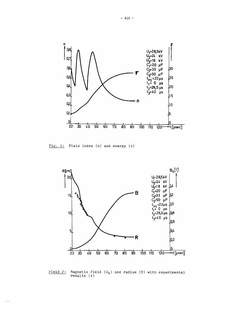
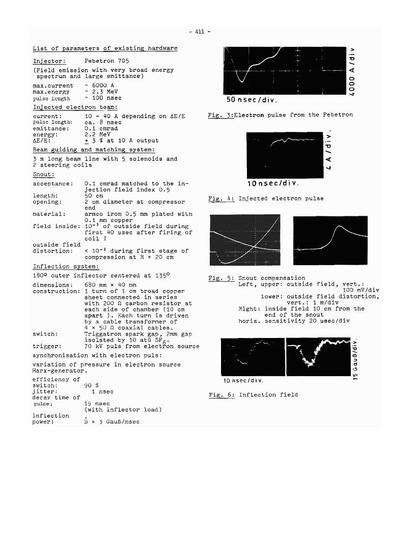
As an injector we use a commerciallyavailable field emission machine: Febetron705. An earlier paper goes into details ofthe machine and describes its beam quality2), Former hopes to take advantage of itsenormous output power (see Fig. 3) byrelatively slight changes on the hardwarecould not be realized. We succeeded inoperating a window less field emission tubebut the brightness of the useful electronbeam could not be raised considerably.Furthermore we found that reproducibilityof the electron pulse requires high qualityvacuum which is for the moment not possiblein connection with our epoxy vacuum chamber.
For the moment an improvement programis going on trying to shape the fieldpattern of the acceleration path of theemission tube by a Pierce optics. A secondFebetron is available for these studies.The intention is to improve the beam quality at least to a level where studies ofcollective effects during compressionand expansion experiments with this generation of compressor become possible. We areaware that the Febetron will not be the
injector of a future heavy ion accelerator- simply because of the restricted repetition rate of its Marx generator.
On the beam line we have changed overfrom quadrupole focusing to solenoids.We found the reason not in physics butin the ease by which solenoids are handled andadaptable to every days modifications.
C. Inflection
Inflection apparatus proved for along time to be the crucial problem for usin producing satisfactory rings. Our usableelectron. pulse is very short and comparable toa single revolution time in the compressor(see Fig. 4), on the other hand the totaljitter of the source is large. Therefore itwas clear that the trigger for the inflector pulse had to come from a stage, fromwhere on jitter was below 1 nsec. We chosethe second stage of the electron sourceMarx-generator as trigger source. It deliversa 70 kV pulse into 50 n. From there on we hada maximum of 120 nsec left for synchronisation, spark gap firing, and cable transferof pulse (at least 105 nsec). The remainingtime for active elements is 15 nsec. Considering this short time we decided on asingle spark gap as switching element forthe inflector pulse:.
The first concept as presented at the4th ERA meeting in Munich B) was based ona short 45 0 inflector within the comDressionchamber. The intention was to give eachelectron a single kick, passing the closedorbit. From a theoretical point of viewand keeping in mind that our injectorallows only for single turn injection weexpected from this single turn inflectionadvantage with respect to the emittanceof the ring. The concept called for avery short pulse fall time and high pulsecurrent. The first requirement could besatisfied by feeding 10 small sub-inflectorsseparately by 10 x 50 n coax cables. Theypresented a load of 5 n to the spark gap.The gaD could be brought to a resistanceof 3 n within 2 nsec. Calculations showedthat the voltage for the charged coaxcables had to be about 100 kV or higher.Experimentally, however, it was not possibleto go considerably beyond 50 kV with normalinsulation techniques at the small dimen-sions for the switch, required to keepdefined connections for the coax cables.We finally decided on SF6 as insulati~ggas for the gap and the complete dc sideof the switch. We tried several methodsto eliminate the reflected pulse from theinflector inductance. Termination of thecables at the inflector side with additional carbon resistors proved to be the
- 409 -
cleanest solution if one accepts to losehalf the inflector power.
The switch and the described inflectorproduced 4 GauB/nsec at 30 kV charging,voltage. This is not enough for a 45 0 1nflector to pull the total input from thesnout, but part of it should have ~een
inflected. However no acceptable r1ng.but anX-ray signal ranging up to 5~ sec after in-jection was observed. A 450 outer inflector,driven by a 90 kV pulser and essentially thesame circuit produced the first poor rings.A 1800 outer inflector finally brought theresults shown in Fig. 9, 10, 11. To checkthe suspected influence of the geometry ofthe 45 0 inflector on the ring stability,we put it as a dummy in addition to theactive 1800 inflector on the compressionchamber. The ring 'diminished to very smallintensities.
D. Coil system and compression cycle
Our coil system and its motivation is describedin earlier papers 3,4). A strong resonance atR = 18 em (n = 0.36) caused heavy losses and forcedus to change our compression program. The snout which is best compensated for a later time (seeFig. 5) 5) - in connection with a 90
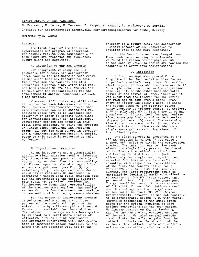
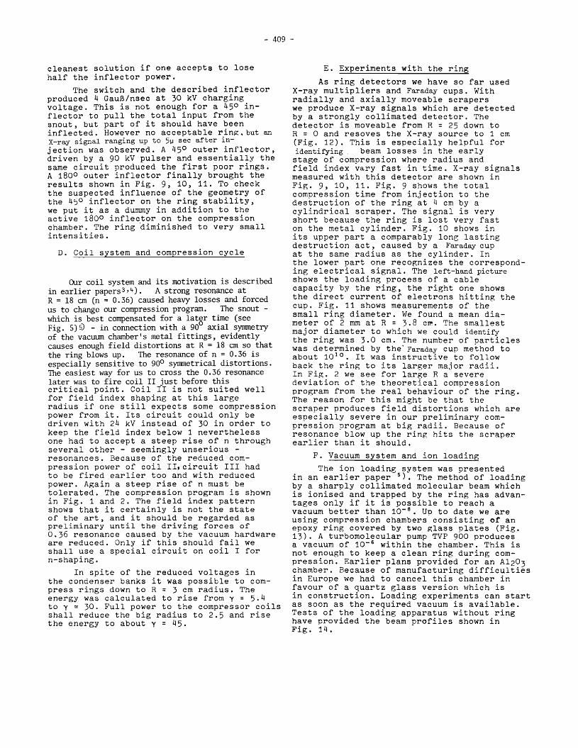
0 axial synnnetryof the vacuum chamber's metal fittings, evidentlycauses enough field distortions at R = 18 em so thatthe ring blows up. The resonance of n = 0.36 isespecially sensitive to 900 synnnetrical distortions.The easiest way for us to cross the 0.36 resonancelater was to fire coil II just before thiscritical point. Coil II is not suited wellfor field index shaping at this largeradius if one still expects some compressionpower from it. Its circuit could only bedriven with 24 kV instead of 30 in order tokeep the field index below 1 neverthelessone had to accept a steep rise of n throughseveral other - seemingly unserious resonances. Because of the reduced compression power of coil II, circuit III hadto be fired earlier too and with reducedpower. Again a steep rise of n must betolerated. The compression program is shownin Fig. 1 and 2. The field index patternshows that it certainly is not the stateof the art, and it should be regarded aspreliminary until the driving forces of0.36 resonance caused by the vacuum hardwareare reduced. Only if this should fail weshall use a special circuit on coil I forn-shaping.
In spite of the reduced voltages inthe condenser banks it was possible to compress rings down to R = 3 cm radius. Theenergy was calculated to rise from y = 5.4to y ~ 30. Full power to the compressor coilsshall reduce the big radius to 2.5 and risethe energy to about y = 45.
E. Experiments with the ring
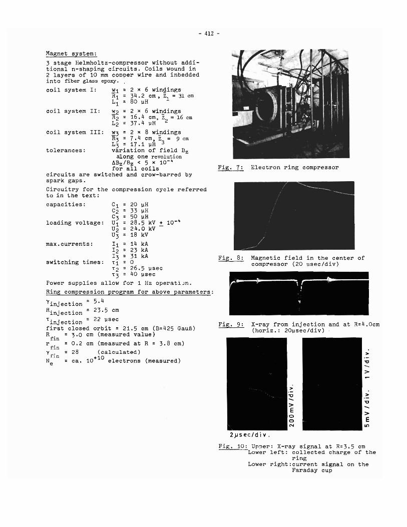
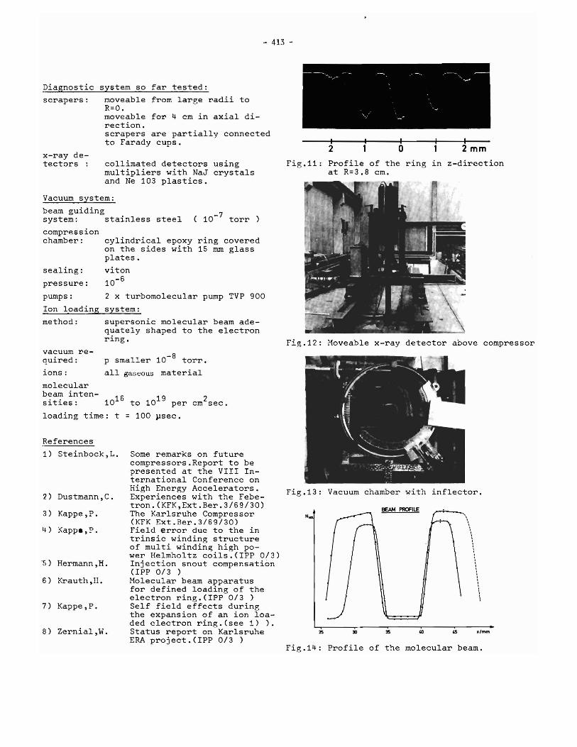
As ring detectors we have so far usedX-ray multipliers and Faraday cupS. Withradially and axially moveable scraperswe produce X-ray signals which are detectedby a strongly collimated detector. Thedetector is moveable from R = 25 down toR = 0 and resoves the X-ray source to 1 cm(Fig. 12). This is especially helpful foridentifying beam losses in the earlystage of compression where radius andfield index vary fast in time. X-ray signalsmeasured with this detector are shown inFig. 9, 10, 11. Fig. 9 shows the totalcompression time from injection to thedestruction of the ring at 4 cm by acylindrical scraper. The signal is veryshort because the ring is lost very faston the metal cylinder. Fig. 10 shows inits upper part a comparably long lastingdestruction act, caused by a Faraday cupat the same radius as the cylinder. Inthe lower part one recognizes the corresponding electrical signal. The left-hand pictureshows the loading process of a cablecapacity by the ring, the right one showsthe direct current of electrons hitting thecup. Fig. 11 shows measurements of thesmall ring diameter. We found a mean diameter of 2 mm at R = 3.8 cm. The smallestmajor diameter to which we could identifythe ring was 3.0 cm. The number of particleswas determined by the' Faraday cup method toabout 1010. It was instructive to followback the ring to its larger major radii.In Fig. 2 we see for large R a severedeviation of the theoretical compressionprogram from the real behaviour of the ring.The reason for this might be that thescraper produces field distortions which areespecially severe in our preliminary compression program at big radii. Because ofresonance blow up the ring hits the scraperearlier than it should.
F. Vacuum system and ion loading
The ion loading system was presentedin an earlier paper 5). The method of loadingby a sharply collimated molecular beam which1S ionised and trapped by the ring has advantages only if it is possible to reach avacuum better than 10- 8
• Up to date we areusing compression chambers~ consisting of anepoxy ring covered by two glass plates (Fig.13). A turbomolecular pump TVP 900 producesa vacuum of 10- 6 within the chamber. This isnot enough to keep a clean ring during compression. Earlier plans provided for an Al203chamber. Because of manufacturing difficultiesin Europe we had to cancel this chamber infavour of a quartz glass version which isin construction. Loading experiments can startas soon as the required vacuum is available.Tests of the loading apparatus without ringhave provided the beam profiles shown inFig. 14.
0.1 cmrad matched to the injection field index 0.550 cm2 cm diameter at compressorendarmco iron 0.5 rnm plated with0.1 mm copper10- 3 of outside field duringfirst 40 ~sec after firing ofcoil I
90 %1 nsec
15 nsec(with inflector load)
acceptance:
material:
outside fielddistortion:
field inside:
length:opening:
switch:
inflectionpower:
< 10- 2 during first stage ofcompression at R = 20 cm
Inflection system:
1800 outer inflector centered at 1350
dimensions: 680 mm x 40 mmconstruction: 1 turn of 1 cm broad copper
sheet connected in serieswith 200 n carbon resistor ateach side of chamber (10 cmapart ). Each turn is drivenby a cable transformer of4 x 50 n coaxial cables.Triggatron spark gap, 2mm gapisolated by 10 atU SF 6 .
trigger: 70 kV puls from electron source
synchronisation with electron puls:
variation of pressure in electron sourceMarx-generator.
efficiency ofswitch:jitter:decay time ofpulse:
- 412 -
Fig. 7: Electron ring compressor
Magnetic field in the center ofcompressor (20 )Jsec/div)
X-ray from injection and at R=4.0cm(horiz.: 20)Jsec/div)
Power supplies allow for 1 Hz operatiJn.Ring compression program for above parameters:
Magnet system:
3 stage Helmholtz-compressor without additional n-shaping circuits. Coils wound in2 layers of 10 mm coo?er wire and inbeddedinto fiber glass epoxy.
coil system I: ~1 = 2 x 6 windin~sRl = 34.2 cm, Zl = 31 emLl = 80 uH
coil system II: ~2 = 2 x 6 windingsR2 = 16.4 cm, Z = 16 emL2 = 37.4)JH 2
coil system III: ~3 = 2 x 8 windingsR3 = 7.4 cm, Z = 9 emL3 = 17.1 )JH 3
tolerances: variation of field Bzalong one revolution
~Bz/Bz < 5 x 10-~
for all coilscircuits are switched and crow-barred byspark gaps.
Circuitry for the compression cycle referredto in the text:
Yinjection = 5.4Rinjection = 23.5 em
Tinjection = 22 ~sec
first closed orbit = 21.5 cm (B=425 GauB)R. = 3.0 cm (measured value)
fl.nr. = 0.2 cm (measured at R = 3.8 cm)
fl.ny = 28 (calculated)
fin 0Ne = ca. 10+ 1 electrons (measured)
Fig. 10: Upper: X-ray signal at R=3.5 cmLower left: collected charge of the
ringLower right:current signal on the
Faraday cup
- 413 -
2mm
.,"""
\\,·,·······,,\
o
BEAM PROFILE
30
2
2S
N
Fig.ll: Profile of the ring in z-directionat R=3.8 cm.
Fig.12: Moveable x-ray detector above compressor
Fig.13: Vacuum chamber with inflector.
Fig.14: Profile of the molecular beam.
ring coveredlS rom glass
Some remarks on futurecompressors.Report to bepresented at the VIII International Conference onHigh Energy Accelerators.Experiences with the Febetron.(KFK,Ext.Ber.3/69/30)The Karlsruhe Compressor(KFK Ext.Ber.3/69/30)Field error due to the intrinsic winding structureof multi winding high power Helmholtz coils.(IPP 0/3)Injection snout compensation(IPP 0/3 )Molecular beam apparatusfor defined loading of theelectron ring.(IPP 0/3 )Self field effects duringthe expansion of an ion loaded electron ring. (see 1) ).Status report on KarlsruheERA project.(IPP 0/3 )
collimated detectors usingmUltipliers with NaJ crystalsand Ne 103 plastics.
2 x turbomolecular pump TVP 900
system:
moveable from large radii toR=O.moveable for 4 cm in axial direction.scrapers are partially connectedto Farady cups.
cylindrical epoxyon the sides withplates.
viton
10-6
p smaller 10-8 torr.
all gaseous material
supersonic molecular beam adequately shaped to the electronring.
system so far tested:Diagnostic
scrapers:
x-ray detectors :
Vacuum system:
beam guidingsystem: stainless steel (10- 7 torr )
compressionchamber:
sealing:
pressure:
pumps:
Ion loading
method:
vacuum required:
ions:
molecularbeam inten-sities: 1016 to 1019 per cm2sec.
loading time: t = 100 psec.
References
1) Steinbock,L.
2) Dustmann,C.
3) Kappe,P.
4) Kappa,P.
"S) Hermann,H.
6) Krauth,H.
7) Kappe,P.
B) Zernial,W.
- 414 -
DISCUSSION
T.K. KHOE : If one were using an ERA as a heavy-ionaccelerator, what would ~ the repetition rate (fora given number of electrons per ring) to obtain lOllheavy particles per second ?
H. HERMANN : The number of possible ions in a ringdepends,besides other facts, on the quality ofthe ring (dimensions) and the expansion rate, butalso on the kind of ions. So the answer to thequestion cannot be a number which holds in general.But to give an idea, if we used protons in a ringof 1013 electrons, one would need about 1 Hzoperation.
A.U. LUCCIO What kind of ions do you plan to injectinto the ring with your molecular-beam apparatus ?
H. HERMANN : The apparatus accepts all kinds ofgaseous material. However, other reasons, forexample the holding power of the ring, might restrictus to certain materials.
H. SCHOPPER : In a heavy-ion accelerator, it isimportant to control the loading of the ring sincethe final energy of the ions depends on the ringloading. Therefore, as has been mentioned, anion-beam device has been developed at Karlsruhe forthis purpose. All atoms that can be put into anion beam can, therefore, be injected into the ring.
May I now ask if there are any new results onself-inflection, a subject that was discussed atprevious conferences ?