Page 1
Thermo-mechanical forming processes
Study Support
doc. Ing. Radim Kocich, Ph.D.
Ostrava 2015
VYSOKÁ ŠKOLA BÁŇSKÁ – TECHNICKÁ UNIVERZITA OSTRAVA
FAKULTA METALURGIE A MATERIÁLOVÉHO INŽENÝRSTVÍ
Page 2
Thermo-mechanical forming processes
2
Title: Thermo-mechanical forming processes
Code:
Author: doc. Ing. Radim Kocich, Ph.D.
Edition: first, 2015
Number of pages:58
Academic materials for the Progressive technical materials study programme at
the Faculty of Metallurgy and Materials Engineering.
Proofreading has not been performed.
Execution: VŠB - Technical University of Ostrava
Page 3
Thermo-mechanical forming processes
3
1. Thermo-mechanical forming processes (controlled forming)
Thermo-mechanical forming controls all the manufacturing conditions with the aim to
achieve the required state of structure. It primarily includes composition of steel and
thermo-mechanical and time parameters of forming and possible cooling. Suitable
structural states enable to achieve higher mechanical properties while maintaining
favourable brittleness, fatigue characteristics and weldability. From the structural point
of view, the most significant factors are grain and sub-grain size, content of the
individual structural components, amount and dispersity of precipitates, dislocations
density and structure of solid solution.
The basic presupposition for achieving high strength properties is an increased
dislocations density; movement of dislocations during an external loading is slowed by
internal barriers. The character of these barriers and their distribution is especially
important for toughness properties, since these enable to relax peak tension stresses by
dislocations movement before the stresses exceed the strength of the material. Barriers
with a low permeability include high-angle grain boundaries, non-plastic structural
particles and non-coherent matrices including Lomer-Cottrel barriers. The opposite
properties have low- or mid-angle grain boundaries, plastic particles and coherent
matrices.
Time to study: 20 hours
Aims After study of this chapter you will be able to
define current methods of thermo-mechanical forming and its basic
mechanisms and division
describe low and high temperature thermo-mechanical processing,
isoforming, deformation aging, forming at low temperatures, SHT –
process, direct rolling, rolling with hot batch
Page 4
Thermo-mechanical forming processes
4
describe basic types of controlled rolling, define controlled cooling
determine mechanical properties of control-formed material
define basic physical metallurgical processes in controlled rolling
Lecture
1.1. Methods of thermo-mechanical processing of steel
The amount of steel processed thermo-mechanically per year is increasing. It can be
assumed that a percentage increase of only 10% (approx. 500kt/year) in production
with the use of thermo-mechanical methods would create a financial profit of approx.
200 million CZK for the Czech Republic. (Short note: Modern production lines
technically enable application of direct thermo-mechanical processing. However, long-
term conceptual directed research would be needed so that modern literature-based
knowledge, experience from conferences and plastometric and semi-operational
(laboratory) experimental results would be fully applicable.) Other advantages of
thermo-mechanical forming (TF) will be further mentioned also for aluminium and
other non-ferrous metals.
In the future, it seems essential to expand these methods of processing. There are
several factors that promote such methods. First is the increase in capability and
decrease in cost of computers of all kinds, which means simulations can be performed
on standard PCs. Second factor is ever deeper understanding of specific phenomena of
TF which enables not only a quantitative description of a process, but also to simulate
forming operations on common computers. The third factor is a gradual application of
TF principles (and also processes which lead to a controlled microstructure
development) in an ever increasing number of commercially made products. A directed
algorithm is finally becoming a successful process for highly specific products and is
expanding its application to more common materials.
As has been stated earlier, TF enables to achieve a specific pre-defined microstructure
that imparts specific mechanical and physical properties. This path is different from
Page 5
Thermo-mechanical forming processes
5
traditional forming processes. TF requires control and interaction of at least these
mechanisms (among others):
dislocation yield and creep
recrystallization
grain growth
phase transformations
precipitation
particle thickening
Most of these structural changes appear dynamically, i.e. during the course of
deformation or statically, i.e. after deformation.
Each of the above mentioned parameters can be studied individually even if the basic
“rules” are not entirely clear. Furthermore, during TF, synthesis of these basic
parameters occurs as well as their mutual interaction. Especially in the area of large
deformations, relatively high temperatures and high deformation speeds, these
phenomena truly are a great unknown so far.
TF can be divided into several individual methods. One of the options could be the
following:
Grain refinement for increase of strength and toughness without any other
further thermal processing.
Grain refinement for achieving superplastic behaviour.
Texture control (minimization of peaks, improved ductility, magnetic
properties …).
Inside each of these categories are processes, which must be solved concurrently. It
requires laboratory simulation as well as computer modelling.
For TMP, two types of steel are usually used:
steels with phase changes (including martensitic),
steels with precipitation of precipitates from oversaturated solid solution
Page 6
Thermo-mechanical forming processes
6
(dispersion strengthening)
1.1.1. Current TMP methods
a) forming before austenite phase change – low- and high-temperature TMP
b) forming during austenite phase change – isoforming
c) forming after austenite phase change – deformation aging, low-temperature forming
Low Temperature TMP (LTMP)
LTMP is based on austenitization with rapid cooling into the range of high stability of
metastable austenite, forming with high degree of deformation ( over 0.6) and
quenching into martensite. Quenching is usually followed by tempering at a lower
temperature. In steels for LTMP, sufficient stability of overcooled austenite is required.
This makes chrome and molybdenum alloyed steels suitable candidates. The main
advantage of LTMP is an increased strength at sufficient plasticity.
High-temperature TMP (HTMP)
The principle is austenitization, forming just over Ar3 with subsequent quenching and
tempering at lower temperatures. It is important that large deformations of austenite
and subsequent quenching occur without recrystallization of austenite. For HTMP, steels
with slow progress of recrystallization are suitable.
In comparison with LTMP, HTMP is technologically simpler, deformation can be
performed in the temperature range between 1 000 to 800 °C. HTMP does not allow
such increase in strength as LTMP, but is does increase plasticity and fatigue resistance.
Isoforming (TBP)
Is based on austenitization and cooling down to the temperature of the perlite nose in
the IRA diagram. Steel is deformed during the entire transformation and subsequently
cooled on air. Tempering is not required. The resulting structure is characterized by
formation of fine sub-grains of ferrite and fine globular carbides. Deformation
temperatures are usually somewhere between 600-700°C, this is sufficient for the
Page 7
Thermo-mechanical forming processes
7
process of polygonization. The deformation is over 0.6. TBP does not significantly
increase the strength properties. However, its main advantage is an increase in
toughness and decrease in transit temperatures.
Deformation aging (DA)
It is processing of either conventionally treated or LTMP processed steel, which is then
formed at a temperature at which aging occurs. For example, a processing with = 0.02
deformation and temperature between 150 and 200 °C. It increases strength, but at the
same time plasticity and impact strength are decreased.
Low temperature forming (LTF)
The initial state is either a state after quenching or a state after annealing. Deformations
after quenching help to achieve strength of up to 3130 MPa.
The aforementioned TMP methods are mostly used for the common types of steel. These
methods do not sufficiently utilize control of structure development through slowed
recrystallization and precipitation kinetics. Nevertheless, newly developed and
introduced methods of controlled rolling of micro-alloyed steels are utilized to make
ferrite grains finer through a transformation from deformed austenite. Slowed
recrystallization of austenite is achieved through the combined effect of micro-alloying
elements in a solid solution and the interaction of controlled precipitation.
1.1.2. Basic types of controlled rolling (CR)
rolling in the lower region of austenite (in two or three stages)
rolling in the region of two-phase structure
method a) complemented by controlled cooling
controlled rolling with quenching and tempering
special methods of CR - for example the SHT (Sumitomo High Toughness) method
Page 8
Thermo-mechanical forming processes
8
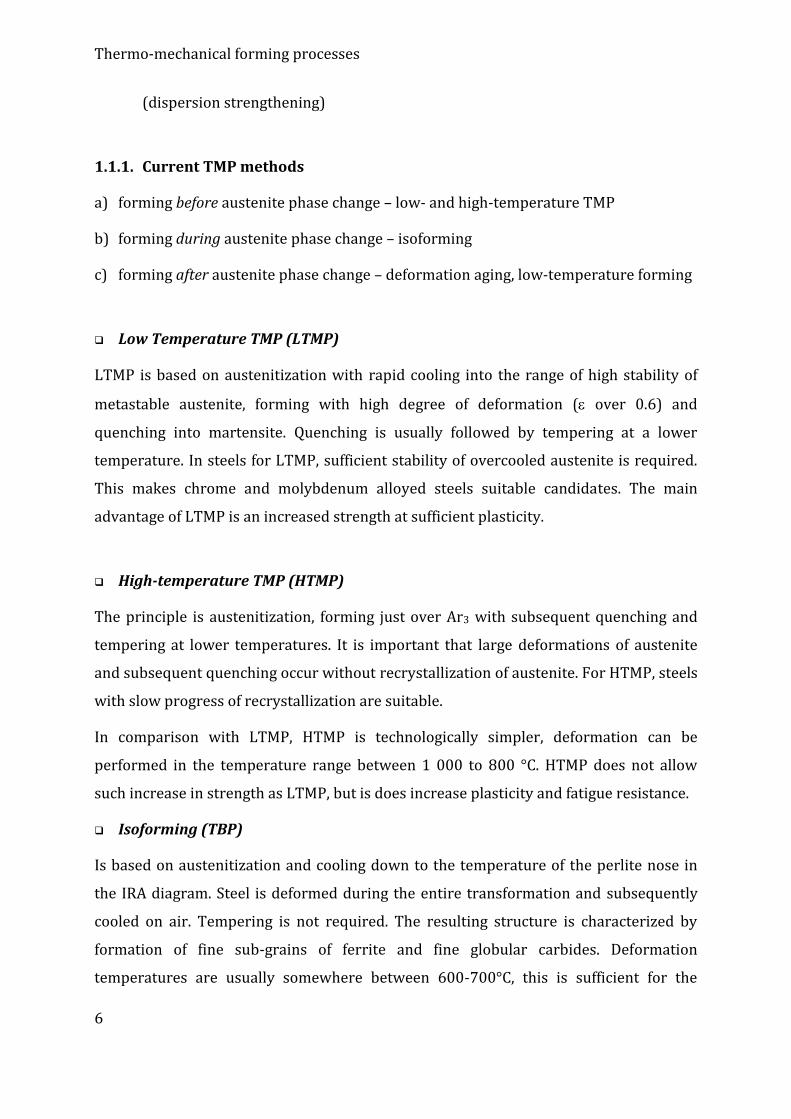
A schematic development of structures during controlled rolling methods can be seen in
figure 1.
Figure 1: A schematic of microstructure development during rolling procedures.
1.2. Properties and characteristics of structure during thermo-
mechanical processing
The main factors that influence yield strength and transition temperature are:
strengthening of solid solution through substitution and interstitial elements
size of ferrite grain
precipitates in ferrite,
content of perlite and its inter-lamellar distance
Peierls-Nabarro stress ( 40 MPa)
During the transformation of from recrystallized austenite, it is possible to
express the yield strength K using the Hall-Petch equation (1).
2/1
0 . dkK (1)
where 0 is internal stress, d is grain size, ky is coefficient expressing the theoretical
value of barrier effect of grain boundaries against movement of dislocations
[MPa.mml/2].
Page 9
Thermo-mechanical forming processes
9
The value of 0 consists of several components and for the transformation of from
non-recrystallized austenite can be expressed by the following relation:
PNPERPRZINS 0 (2)
If the deformation is ended in the + dual-phase area, the final structure consists of
recrystallized ferrite grains and subgrains. Since all the grain boundaries in such a
structure restrict the movement, the d value has to be replaced with the de effective
grain size value (Eq. 3).
rcrre fdfdd
1..111
(3)
where de-1 is length of boundaries for a unit length, dr-1 is length of high-angle
boundaries, dc-1 is length of low-angle boundaries, fr is volume fraction of recrystallized
ferrite.
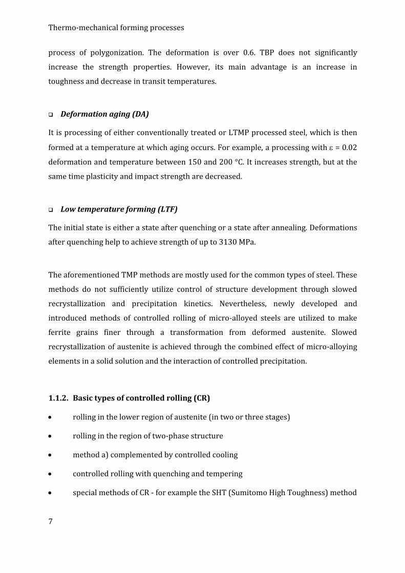
1.2.1. Misorientation of grain boundary angle, types of grain boundaries
One of the first steps during TMP is to modify a coarse as-cast structure. One of the
aspects according to which structure – grain boundaries – can be distinguished is the
character of their rotation and/or tilt (also called misorientation). Several basic types
of grain boundaries can be observed (Figure 2).
Figure 2: Possible types of grain boundaries and their energies.
A tilted boundary with a low misorientation angle consists of a field of parallel edge
dislocations. A higher amount of dislocations causes higher misorientation angle and a
consequent increase in energy. Nevertheless, the speed of the increase decreases at
higher energy or amount of dislocations due to mutual annihilation of dislocation fields.
Besides the misorientation angle and distance between dislocations, the dependency of
Page 10
Thermo-mechanical forming processes
10
grain boundary energy on misorientation angle θ can also be disturbed by dislocations
cores overlapping. This then creates a transfer between low-angle grain boundaries
(LAGBs) and high-angle grain boundaries (HAGBs).
Special boundaries are locations in which two crystals overlap with a relatively small
curvature of inter-atomic layers. This phenomenon is also the basis of the CSL
(coincident site lattice) model, which in principle describes overlapping of selected
locations in lattices. For example, if every 5th lattice point is overlapped, then the
boundary is denoted as Σ5 etc. Except several exceptions the predicted limits for cubic
lattices are Σ29 or Σ33. Nevertheless, the CLS index only rarely depicts the exact
boundary. The CSL model is also valid only for 2D systems, while in real conditions the
material system is 3D. Another fact is that the data were derived for cubic systems,
whereas for non-cubic systems the situation is more complicated.
1.2.2. Deformation bands
Plastic deformation is influenced by changes of the stress state imparted by interactions
of dislocations with grain boundaries and obstacles. Actually, each individual grain
within the material deforms in an entirely heterogenous way influenced by the
neighboring grains being deformed. This was proven by microhardness measurements
resulting into different values for individual grains.
The final deformation substructure is dependent not only on the temperature and way
of deformation, but also on grains orientations and local deformations. This means that
the tensors of deformation can differ inside one single grain due to accommodation of
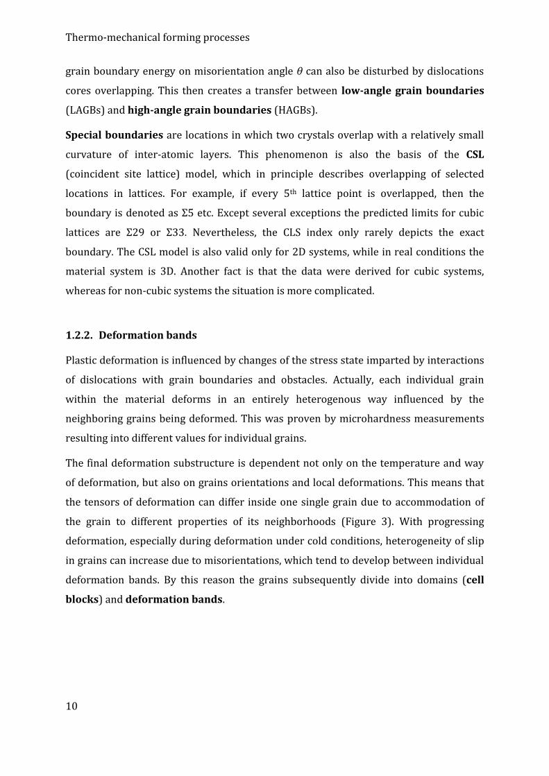
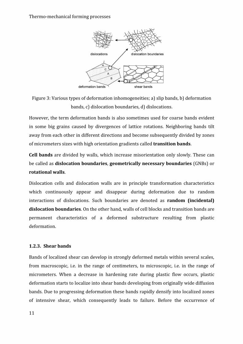
the grain to different properties of its neighborhoods (Figure 3). With progressing
deformation, especially during deformation under cold conditions, heterogeneity of slip
in grains can increase due to misorientations, which tend to develop between individual
deformation bands. By this reason the grains subsequently divide into domains (cell
blocks) and deformation bands.
Page 11
Thermo-mechanical forming processes
11
Figure 3: Various types of deformation inhomogeneities; a) slip bands, b) deformation
bands, c) dislocation boundaries, d) dislocations.
However, the term deformation bands is also sometimes used for coarse bands evident
in some big grains caused by divergences of lattice rotations. Neighboring bands tilt
away from each other in different directions and become subsequently divided by zones
of micrometers sizes with high orientation gradients called transition bands.
Cell bands are divided by walls, which increase misorientation only slowly. These can
be called as dislocation boundaries, geometrically necessary boundaries (GNBs) or
rotational walls.
Dislocation cells and dislocation walls are in principle transformation characteristics
which continuously appear and disappear during deformation due to random
interactions of dislocations. Such boundaries are denoted as random (incidental)
dislocation boundaries. On the other hand, walls of cell blocks and transition bands are
permanent characteristics of a deformed substructure resulting from plastic
deformation.
1.2.3. Shear bands
Bands of localized shear can develop in strongly deformed metals within several scales,
from macroscopic, i.e. in the range of centimeters, to microscopic, i.e. in the range of
micrometers. When a decrease in hardening rate during plastic flow occurs, plastic
deformation starts to localize into shear bands developing from originally wide diffusion
bands. Due to progressing deformation these bands rapidly densify into localized zones
of intensive shear, which consequently leads to failure. Before the occurrence of
Page 12
Thermo-mechanical forming processes
12
macroscopic bands shear bands can occur within a grain and subsequently develop
through several grains. Alloys hardened with fine precipitates, fine twins or alloys with
high dislocation density are especially prone to development of this type of shear bands.
1.2.4. Structure development
Significantly different conditions for structure development of steel occur with different
deformation temperatures.
Region I – recrystallization
The original grain size is a function of temperature and material metallurgical character.
Refinement of austenite grains is given by the particular deformation-recrystallization
cycle. Nuclei for the transformation occur only on boundaries of austenite grains.
The final size of ferrite grains is limited by a certain limit value and its further decrease
beyond this limit using the deformation-recrystallization cycle within region I is not
possible. Eventually, relatively coarse ferrite grains develop after transformation.
Region II – without recrystallization
Forming within region I results into achievement of a limit grain size. Further grain
refinement can be achieved by forming in region II. Austenite grains elongate as a
consequence of restricted recrystallization and bands with higher dislocation density
and higher inner energy and instability develop inside them. Ferrite nuclei develop not
only on austenite grain boundaries, but also within deformation bands – deformation
bands have an effect similar to the effect of grain boundaries during the
transformation.
Region III – austenite–ferrite
Further grain refinement can be achieved by forming in region III (dual-phase). Ferrite
grains deformed after the occurrence of transformation cannot recrystallize
anymore and subgrains occur during subsequent recovery. A decreased solubility of Mn
and V in ferrite after the transformation fastens stress-induced precipitation,
which contributes to pile-up of dislocations and sub-boundaries. Grain growth is also
suppressed in the dual-phase region. The result of forming in region III is therefore a
mixed structure consisting of equiaxed ferrite grains, grains not deformed after the
Page 13
Thermo-mechanical forming processes
13
transformation, grains with a lower dislocation density (soft) and subgrains with a
higher dislocation density (hard).
1.3. Structural features during controlled forming
1.3.1. Dissolution of carbides and nitrides, grain growth
One of the aims of heating to a forming temperature is to dissolve the largest possible
amount of precipitates into a solid solution. At the same time, conditions for critical
grain growth must not be reached. Solubility of precipitates (nitrides and carbides) can
be determined using corresponding equations and can also be influenced by other
elements present in steels, especially Mn and Si. Si decreases solubility of Ti in steels.
Titanium bonded in stable compounds does not influence solubility of carbides. It is
therefore necessary to consider only free Ti.
Grain growth is influenced by the amount of impurities and alloying elements present in
solid solution and by second phase particles. These reduce grain areas and pin grain
boundaries. Increasing amount of Nb and Ti in steels increases critical temperature for
grain growth. Vanadium does not restrict grain growth so significantly as Ti and Nb.
Vanadium carbides are less stable and dissolve at lower temperatures.
1.3.2. Strain hardening during TMP
Strain hardening during controlled forming is controlled by the amount of energy
imposed into a material as a result of plastic deformation. It is a consequence of an
increase in stress caused by dislocation movement more or less restricted by obstacles
(precipitates, grain boundaries etc.), which they have to surpass during their movement.
Stacking fault energy of a deformed material defines the possibility of dislocations to be
dissociated into partial dislocations and stacking faults within slip planes. A low stacking
fault energy (lower than 50 mJ/m2) usually results into dissociation of full dislocations
into wide partial dislocations. This subsequently limits their movement only to slip
planes and alternative dislocation movements, such as localized cross-slip, out of these
planes become extremely difficult (i.e. improbable). At lower strains, these dislocations
usually accumulate in slip planes, interact with dislocations in different slip systems and
Page 14
Thermo-mechanical forming processes
14
form planar dislocation structures, which consequently lead to a development of high
localized stress gradients. At higher strains, materials with a low stacking fault energy
usually tend to form microtwins (or possibly localized martensitic transformations) and
shear bands. They are therefore prone to form evident planar faults of crystal lattice or
local orientations. Depending on the stacking fault energy it is possible to divide the
development of deformation stress into the four following stages.
Stage 1:
Movement of dislocations within their slip planes is usually restricted and no mutual
interactions occur. By this reason, the velocity of strain hardening is very low. Plastic
deformation results into rotation of crystals, which leads to their reorientation and
multiple slip, which results into a stronger interaction of dislocations in stage 2. Stage 1
is neglectable for commercial polycrystalline materials since the movement of the first
dislocations is limited by grain boundaries, at which dislocations usually pile-up. The
resistance to overcome these boundaries can be expressed using a modified Hall-Petch
relation (4).
2
1
1
Dk)D( (4)
where is deformation resistance for a very large grain, coefficient k1 is usually 0.7 for
carbon steel, 0.2 to 0.4 for HCP lattice metals, 0.07 to 0.1 for Cu and Al, respectively.
Presence of carbon in a solid solution significantly increases the k coefficient value.
Stage 2:
Mutual interactions of dislocations in various slip systems cause fast multiplication of
dislocations and a subsequent high and approximately constant hardening rate.
Development of 3D fields consisting of dislocation multipoles (Taylor networks) occur in
metals with low stacking fault energies, while dislocation tangles develop and often form
into cellular patterns in metals with high stacking fault energies. Typical strain values
characterizing this stage are 0.05 – 0.2.
Stage 3:
At strain values approximately up to 1 the deformation curve becomes parabolic. Strain
hardening rate decreases progressively down to values approximately an order of
Page 15
Thermo-mechanical forming processes
15
magnitude lower than at stage 2. In this stage, the effect of the dislocation multiplication
process is reduced by dislocation annihilation (dynamic recovery due to localized cross-
slip, climb or mutual elimination of segments of opposite signs). Microstructure
development is towards a clearly defined cell substructure consisting of dislocation cell
walls. However, this results into a significant decrease in dislocation density inside cells.
The individual cell walls are at first created by a complex of dislocation tangles, which
subsequently reduce their thicknesses with progressing deformation (individual
dislocations move closer to each other). Cells dimensions reduce during deformation
from several micrometers to tenths of micrometers. At the same time misorientation of
individual cells increases from the original value of 1° up to 3° to 4° and even more.
Stage 4:
At strains higher than 1 many grains disintegrate into bands of various orientations
divided by transition zones and grain boundaries. A formation of lamellar structure
consisting of disoriented microbands parallel to the rolling direction occurs at very high
strains. Strain hardening rate in this stage is not very high, although it remains almost
constant. Therefore, increase in deformation stress can occur at high strains.
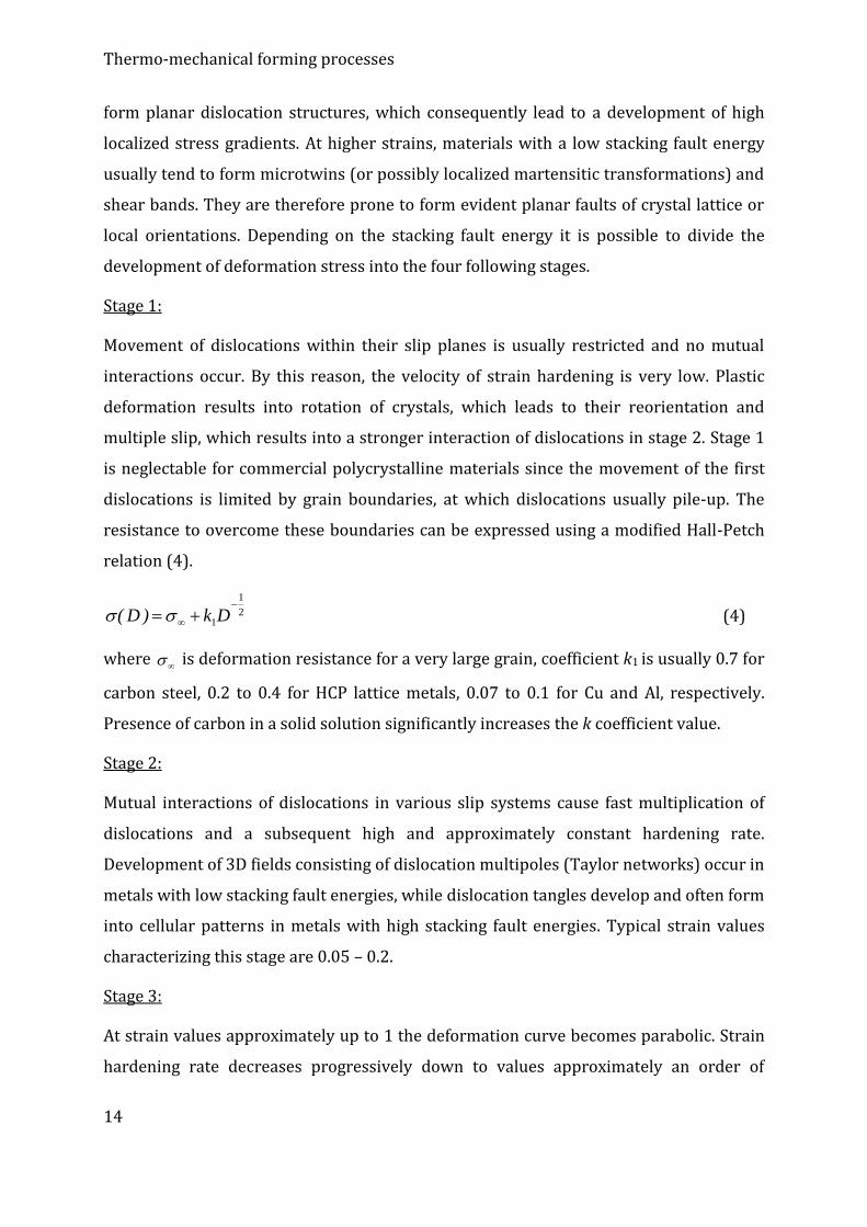
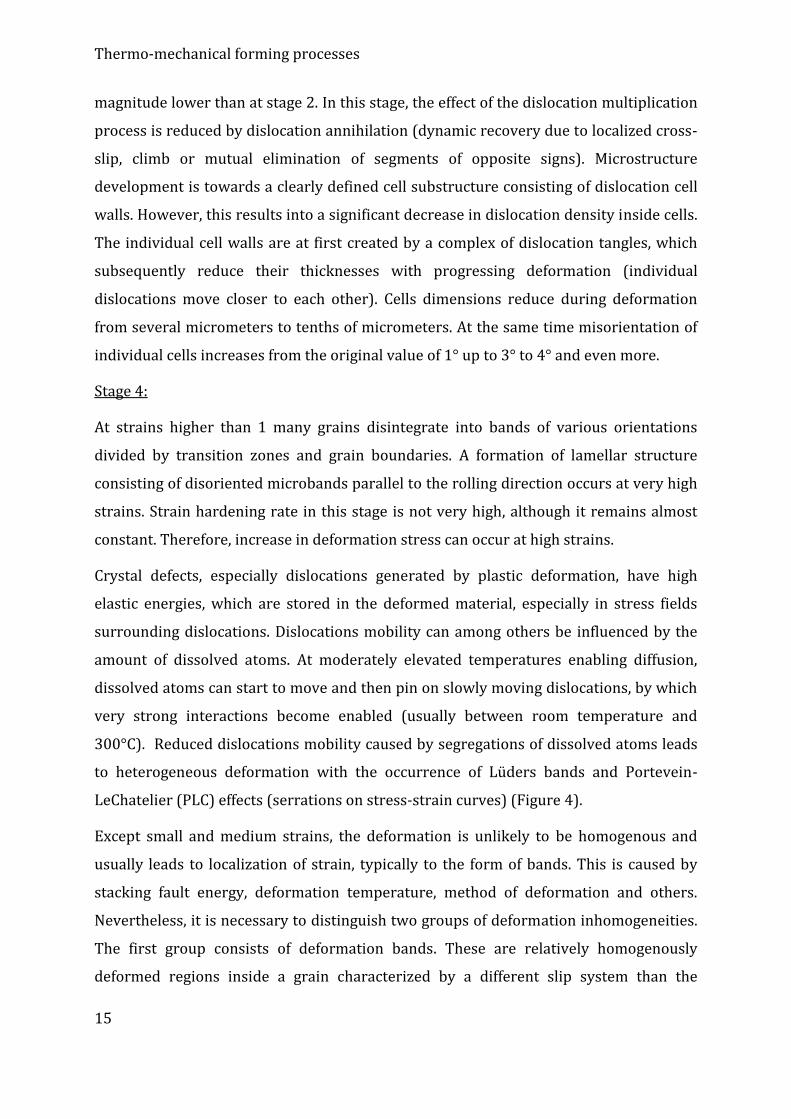
Crystal defects, especially dislocations generated by plastic deformation, have high
elastic energies, which are stored in the deformed material, especially in stress fields
surrounding dislocations. Dislocations mobility can among others be influenced by the
amount of dissolved atoms. At moderately elevated temperatures enabling diffusion,
dissolved atoms can start to move and then pin on slowly moving dislocations, by which
very strong interactions become enabled (usually between room temperature and
300°C). Reduced dislocations mobility caused by segregations of dissolved atoms leads
to heterogeneous deformation with the occurrence of Lüders bands and Portevein-
LeChatelier (PLC) effects (serrations on stress-strain curves) (Figure 4).
Except small and medium strains, the deformation is unlikely to be homogenous and
usually leads to localization of strain, typically to the form of bands. This is caused by
stacking fault energy, deformation temperature, method of deformation and others.
Nevertheless, it is necessary to distinguish two groups of deformation inhomogeneities.
The first group consists of deformation bands. These are relatively homogenously
deformed regions inside a grain characterized by a different slip system than the
Page 16
Thermo-mechanical forming processes
16
neighboring regions within the grain. The second group is shear bands. These are areas
of very strong localized slip within a grain, as well as through many grains. Both the
groups lead to dissociation of a gran into subgrains, although by different mechanisms.
Figure 4: Stress-strain curve with evident PLC effect (Al-Mg alloy).
1.3.3. Precipitation
Defects caused by plastic deformation support diffusion of micro-alloying elements and
nucleation of precipitates. As a consequence, a quick strain-induced type of precipitation
occurs. Moreover, plastic deformation decreases solubility of micro-alloying elements,
which also fastens precipitation. The influence of plastic deformation (ε = 0.09) on
solubility of Nb(CN) was expressed by Yamamoto (Eq. 5).
TNCNb /657093,114
12.log
(5)
Strain-induced precipitation occurring during controlled rolling is especially important
during softening processes. While coarse non-dissolved particles (>0.1 m) already
present in the structure before deformation concentrate strain in their vicinity and
therefore support recrystallization, strain-induced precipitates cause its significant
delay. Recrystallization is also inhibited by micro-alloying atoms present in solid
solution. The differences in size and electron structure of the micro-alloying atoms and
the matrix support their segregation in stacking faults areas, which consequently
Page 17
Thermo-mechanical forming processes
17
changes stacking fault energies. This causes inhibition of dislocation movement and
redistribution of dislocations, which makes nucleation of recrystallization nuclei more
difficult.
The substantial delaying effect of strain-induced precipitates on recrystallization
kinetics can be primarily explained by the fact that precipitation occurs especially on
sub-boundaries of deformed austenite. The most effective inhibitors of grain boundaries
movement during recrystallization are fine strain-induced precipitates with the
diameter smaller than 6nm. Development of recrystallization processes is driven by
particles coarsening rate during deformation. The region of precipitates formation is
usually between 850 and 1000°C. The coarsening rate at the temperature of 1000°C is
significant, while at 950°C it decreases substantially and coarsening is not evident even
at longer dwelling times at the temperature of 850°C. For an effective inhibition of
recrystallization at least 0.02% of Nb in solid solution is necessary.
Precipitation kinetics in austenite and ferrite can generally be described by ARA
diagrams. The T0 temperature is the temperature at which the Nb(CN) and Fe3C
precipitation curves cross each other. Precipitation of Fe3C at temperatures below Ar1
and at the same time above T0 is improbable, since precipitation of Nb(CN) occurs faster
due to its lower free energy when compared to Fe3C. At temperatures below T0 the
diffusion ability of Nb in ferrite as a control mechanism of precipitation on the phase
boundary of γ/α is lower. Therefore, Nb(CN) precipitates non-uniformly throughout the
entire material volume. During forming in the region between the Ar3 and Ar1
temperatures precipitates segregate in parallel layers. Origination of these layers is most
probably in precipitation on γ/α phase boundaries during transformation. Such
precipitates do not significantly increase strength.
Incubation time for static precipitation is in the order of magnitude of 102 s at 950°C. For
strain-induced precipitation this time shortens by one order of magnitude, while it
shortens even by two orders of magnitude for dynamic precipitation.
Page 18
Thermo-mechanical forming processes
18
1.3.4. Recovery
Recovery occurs when a non-equilibrium concentration of lattice defects (point and line
defects) is decreased, usually by annealing at an appropriate temperature. Point defects
are already recovered at relatively low temperatures (below 0.3 Tt), i.e. below the
temperatures of TMPs of most materials. Recrystallization dominates at higher
temperatures, although recovery also occurs since kinetics is higher at higher
temperatures.
For metals with higher stacking fault energies (e.g. Al), processes such as dislocation
cross-slip and local annihilation proceed easily, which supports recovery. On the other
hand, for metals with low stacking fault energies (e.g. austenitic steels, -brass), the
recovery process is not much evident before recrystallization. The same phenomenon
applies for alloys with a high amount of atoms dissolved in solid solution reducing
dislocation mobility. Recovery can occur immediately after plastic deformation, but also
during deformation. Nevertheless, recovery does not influence the appearance of
microstructure or crystallographic texture. It influences properties, such as hardness,
dislocation density, size and misorientation of subgrains. However, the changes can only
hardly be detected.
Mechanisms applied during recovery
- annihilation of point defects (vacancies, interstitions) using diffusion e.g. into
dislocations
- mutual annihilations of dislocations (applies for closely located dislocations of
opposite signs or dipoles, for which a low amount of dislocation climb or cross-
slip is needed)
- rearrangement of free dislocations and random dislocations into dislocation
walls or sub-boundaries (polygonization)
- coalescence of sub-boundaries walls during subgrains growth
It is very difficult to distinguish the process of diffusion of dislocation cells into clearly
defined subgrain boundaries from the process of grain growth. This is especially due to
the heterogeneity of dislocation structure in deformed polycrystalline materials. The
late stage of recovery (formation of clearly defined sub-boundaries) is often the first
Page 19
Thermo-mechanical forming processes
19
stage of nucleation during recrystallization, which can lead to a fast recrystallization
stopping further recovery.
Structural changes during recovery
Besides the first fast decrease in volume of point defects, the main structural changes
can be divided as follows.
- rearrangement of dislocations into cell structures (for metals with high stacking
fault energies and most of metals formed under hot conditions this proceeds
together with deformation)
- elimination of free dislocations inside cells
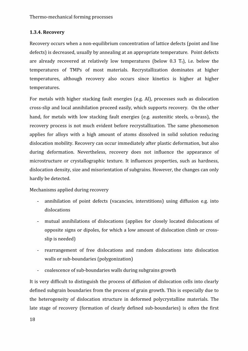
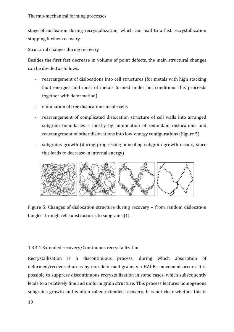
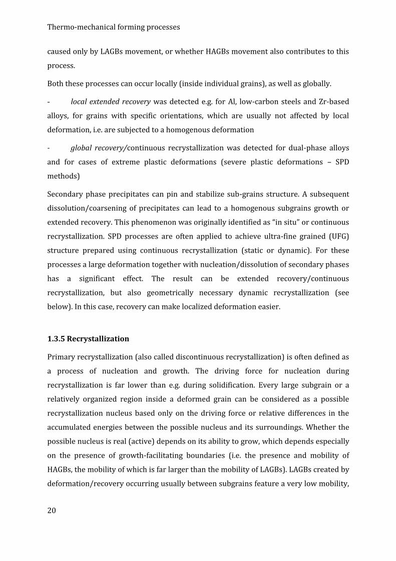
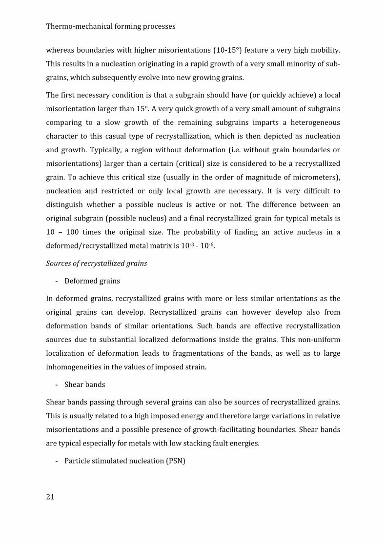
- rearrangement of complicated dislocation structure of cell walls into arranged
subgrain boundaries – mostly by annihilation of redundant dislocations and
rearrangement of other dislocations into low-energy configurations (Figure 5)
- subgrains growth (during progressing annealing subgrain growth occurs, since
this leads to decrease in internal energy)
Figure 5: Changes of dislocation structure during recovery – from random dislocation
tangles through cell substructures to subgrains [1].
1.3.4.1 Extended recovery/Continuous recrystallization
Recrystallization is a discontinuous process, during which absorption of
deformed/recovered areas by non-deformed grains via HAGBs movement occurs. It is
possible to suppress discontinuous recrystallization in some cases, which subsequently
leads to a relatively fine and uniform grain structure. This process features homogenous
subgrains growth and is often called extended recovery. It is not clear whether this is
Page 20
Thermo-mechanical forming processes
20
caused only by LAGBs movement, or whether HAGBs movement also contributes to this
process.
Both these processes can occur locally (inside individual grains), as well as globally.
- local extended recovery was detected e.g. for Al, low-carbon steels and Zr-based
alloys, for grains with specific orientations, which are usually not affected by local
deformation, i.e. are subjected to a homogenous deformation
- global recovery/continuous recrystallization was detected for dual-phase alloys
and for cases of extreme plastic deformations (severe plastic deformations – SPD
methods)
Secondary phase precipitates can pin and stabilize sub-grains structure. A subsequent
dissolution/coarsening of precipitates can lead to a homogenous subgrains growth or
extended recovery. This phenomenon was originally identified as “in situ” or continuous
recrystallization. SPD processes are often applied to achieve ultra-fine grained (UFG)
structure prepared using continuous recrystallization (static or dynamic). For these
processes a large deformation together with nucleation/dissolution of secondary phases
has a significant effect. The result can be extended recovery/continuous
recrystallization, but also geometrically necessary dynamic recrystallization (see
below). In this case, recovery can make localized deformation easier.
1.3.5 Recrystallization
Primary recrystallization (also called discontinuous recrystallization) is often defined as
a process of nucleation and growth. The driving force for nucleation during
recrystallization is far lower than e.g. during solidification. Every large subgrain or a
relatively organized region inside a deformed grain can be considered as a possible
recrystallization nucleus based only on the driving force or relative differences in the
accumulated energies between the possible nucleus and its surroundings. Whether the
possible nucleus is real (active) depends on its ability to grow, which depends especially
on the presence of growth-facilitating boundaries (i.e. the presence and mobility of
HAGBs, the mobility of which is far larger than the mobility of LAGBs). LAGBs created by
deformation/recovery occurring usually between subgrains feature a very low mobility,
Page 21
Thermo-mechanical forming processes
21
whereas boundaries with higher misorientations (10-15°) feature a very high mobility.
This results in a nucleation originating in a rapid growth of a very small minority of sub-
grains, which subsequently evolve into new growing grains.
The first necessary condition is that a subgrain should have (or quickly achieve) a local
misorientation larger than 15°. A very quick growth of a very small amount of subgrains
comparing to a slow growth of the remaining subgrains imparts a heterogeneous
character to this casual type of recrystallization, which is then depicted as nucleation
and growth. Typically, a region without deformation (i.e. without grain boundaries or
misorientations) larger than a certain (critical) size is considered to be a recrystallized
grain. To achieve this critical size (usually in the order of magnitude of micrometers),
nucleation and restricted or only local growth are necessary. It is very difficult to
distinguish whether a possible nucleus is active or not. The difference between an
original subgrain (possible nucleus) and a final recrystallized grain for typical metals is
10 – 100 times the original size. The probability of finding an active nucleus in a
deformed/recrystallized metal matrix is 10-3 - 10-6.
Sources of recrystallized grains
- Deformed grains
In deformed grains, recrystallized grains with more or less similar orientations as the
original grains can develop. Recrystallized grains can however develop also from
deformation bands of similar orientations. Such bands are effective recrystallization
sources due to substantial localized deformations inside the grains. This non-uniform
localization of deformation leads to fragmentations of the bands, as well as to large
inhomogeneities in the values of imposed strain.
- Shear bands
Shear bands passing through several grains can also be sources of recrystallized grains.
This is usually related to a high imposed energy and therefore large variations in relative
misorientations and a possible presence of growth-facilitating boundaries. Shear bands
are typical especially for metals with low stacking fault energies.
- Particle stimulated nucleation (PSN)
Page 22
Thermo-mechanical forming processes
22
Dislocations can be pinned by relatively large particles insusceptible to slip. This pinning
and subsequent growth of dislocation density leads to formations of locally deformed
regions with large developments of misorientations around secondary phase particles.
Consequently, recrystallization occurs in these locally deformed regions due to large
differences in the imposed energies. This type of recrystallization is usually depicted as
PSN (particle stimulated nucleation). Locally deformed regions around particles are then
depicted as PSN grains with random orientations.
Low-temperature annealing performed after deformation often results in a highly
random orientation, which is caused by the existence of inner and outer locally
deformed regions, or by the influence of PSN and deformation bands.
One of the mechanisms by which a recrystallized grain with a new orientation can
originate is also recrystallization twins. These occur especially in metals with low
stacking fault energies (Cu, austenitic steel).
As was already mentioned, particles are very important during recrystallization, since
they can pin grain boundaries during their movement. However, there are more types of
the pinning effect.
- Pinning by Zener drag. Low-energy boundaries, such as CSL boundaries, have low
Zener drag pinning effect.
- Pinning using elements dissolved in solid solution (solute drag). The effect is low
for CSL boundaries.
- Orientation pinning. Growing grains can be pinned by locally deformed regions of
similar orientations, i.e. by a presence of LAGBs.
Possible types of recrystallization
- Dynamic recrystallization
Under certain conditions, a structure can recrystallize during deformation, i.e.
dynamically. Occurrence of this type of recrystallization is theoretically possible also
during deformation under cold conditions, although it is practically observed only rarely
(for very pure metals). Dynamic recrystallization can either be discontinuous,
geometrical or based on a progressive rotation of subgrains. The latter two types are
Page 23
Thermo-mechanical forming processes
23
based on the presupposition of imposed strain with a limited or restricted movement of
HAGBs.
- Discontinuous dynamic recrystallization
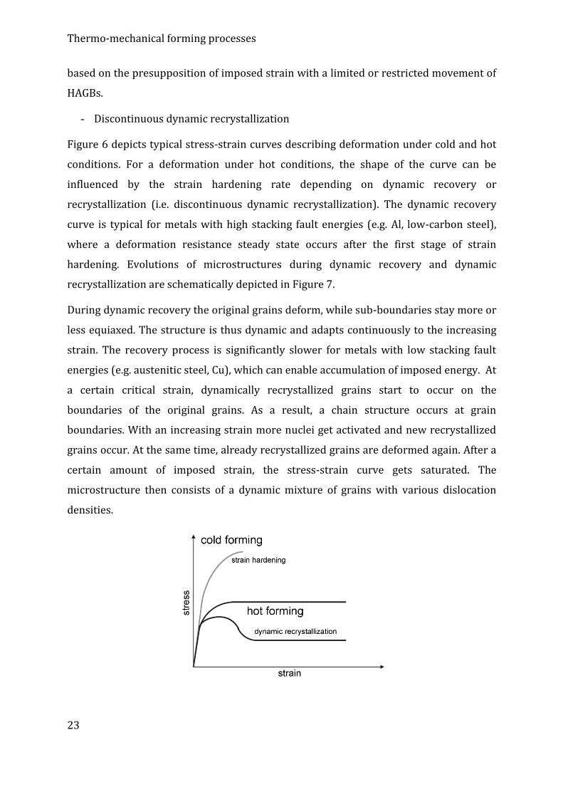
Figure 6 depicts typical stress-strain curves describing deformation under cold and hot
conditions. For a deformation under hot conditions, the shape of the curve can be
influenced by the strain hardening rate depending on dynamic recovery or
recrystallization (i.e. discontinuous dynamic recrystallization). The dynamic recovery
curve is typical for metals with high stacking fault energies (e.g. Al, low-carbon steel),
where a deformation resistance steady state occurs after the first stage of strain
hardening. Evolutions of microstructures during dynamic recovery and dynamic
recrystallization are schematically depicted in Figure 7.
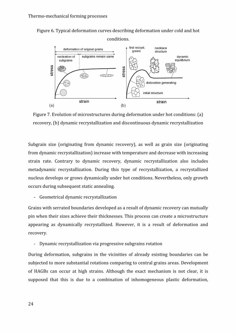
During dynamic recovery the original grains deform, while sub-boundaries stay more or
less equiaxed. The structure is thus dynamic and adapts continuously to the increasing
strain. The recovery process is significantly slower for metals with low stacking fault
energies (e.g. austenitic steel, Cu), which can enable accumulation of imposed energy. At
a certain critical strain, dynamically recrystallized grains start to occur on the
boundaries of the original grains. As a result, a chain structure occurs at grain
boundaries. With an increasing strain more nuclei get activated and new recrystallized
grains occur. At the same time, already recrystallized grains are deformed again. After a
certain amount of imposed strain, the stress-strain curve gets saturated. The
microstructure then consists of a dynamic mixture of grains with various dislocation
densities.
Page 24
Thermo-mechanical forming processes
24
Figure 6. Typical deformation curves describing deformation under cold and hot
conditions.
Figure 7. Evolution of microstructures during deformation under hot conditions: (a)
recovery, (b) dynamic recrystallization and discontinuous dynamic recrystallization
Subgrain size (originating from dynamic recovery), as well as grain size (originating
from dynamic recrystallization) increase with temperature and decrease with increasing
strain rate. Contrary to dynamic recovery, dynamic recrystallization also includes
metadynamic recrystallization. During this type of recrystallization, a recrystallized
nucleus develops or grows dynamically under hot conditions. Nevertheless, only growth
occurs during subsequent static annealing.
- Geometrical dynamic recrystallization
Grains with serrated boundaries developed as a result of dynamic recovery can mutually
pin when their sizes achieve their thicknesses. This process can create a microstructure
appearing as dynamically recrystallized. However, it is a result of deformation and
recovery.
- Dynamic recrystallization via progressive subgrains rotation
During deformation, subgrains in the vicinities of already existing boundaries can be
subjected to more substantial rotations comparing to central grains areas. Development
of HAGBs can occur at high strains. Although the exact mechanism is not clear, it is
supposed that this is due to a combination of inhomogeneous plastic deformation,
Page 25
Thermo-mechanical forming processes
25
accelerated recovery (in regions in the vicinities of grain boundaries) and grain
boundary sliding.
1.3.6. Grain coarsening (growth)
Grain growth after recrystallization is controlled especially by surface energy or grain
boundary energy. This driving force is by two orders of magnitude lower than driving
force for recrystallization. A more correct description for this grain growth process is
grain coarsening (sometimes also secondary recrystallization).
There are two basic types of grain coarsening: normal and abnormal. During normal
coarsening, the main mechanism is elimination of finest grains, while the grain size
distribution remains almost constant. During abnormal coarsening, growth of several
grains inside a pinned structure occurs. The pinning effect is usually caused by particles
of other phases or by low misorientation angles (i.e. low grain boundaries mobility). The
grain growth driving force is substantially lowered if the grain size achieves
approximately ½ of the thickness of the deformed sample. This is due to a reduced grain
boundary radius. At the grain boundaries equilibrium state, the force has to act
perpendicular to the sample surface. Moreover, grooves develop in the intersection of
grain boundaries with the surface, which restrict grain boundaries movement.
Due to a very high number of influencing factors it is not possible to determine in
advance when and how abnormal grain growth will occur.
1.4. Alternative deformation mechanisms
Although slip is the dominant deformation mechanism for most of metal materials,
activation of different mechanisms is possible under certain conditions. Among these are
twinning, creep, grain boundary sliding (GBS), and deformation related to phase
transformations. Various deformation mechanisms can be active during deformation
under hot conditions depending on the temperature and applied stress. To define areas,
in which the individual deformation mechanisms can be expected to occur, deformation
mechanisms maps are used. The maps practically bring information about the influence
Page 26
Thermo-mechanical forming processes
26
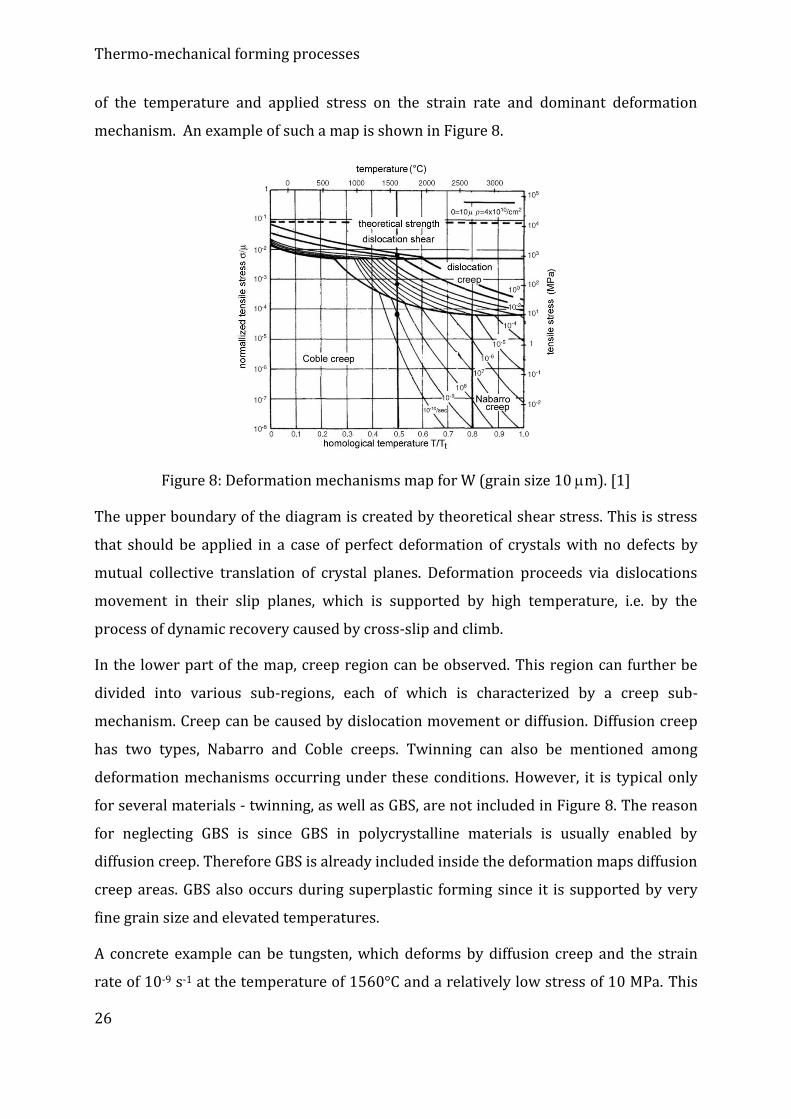
of the temperature and applied stress on the strain rate and dominant deformation
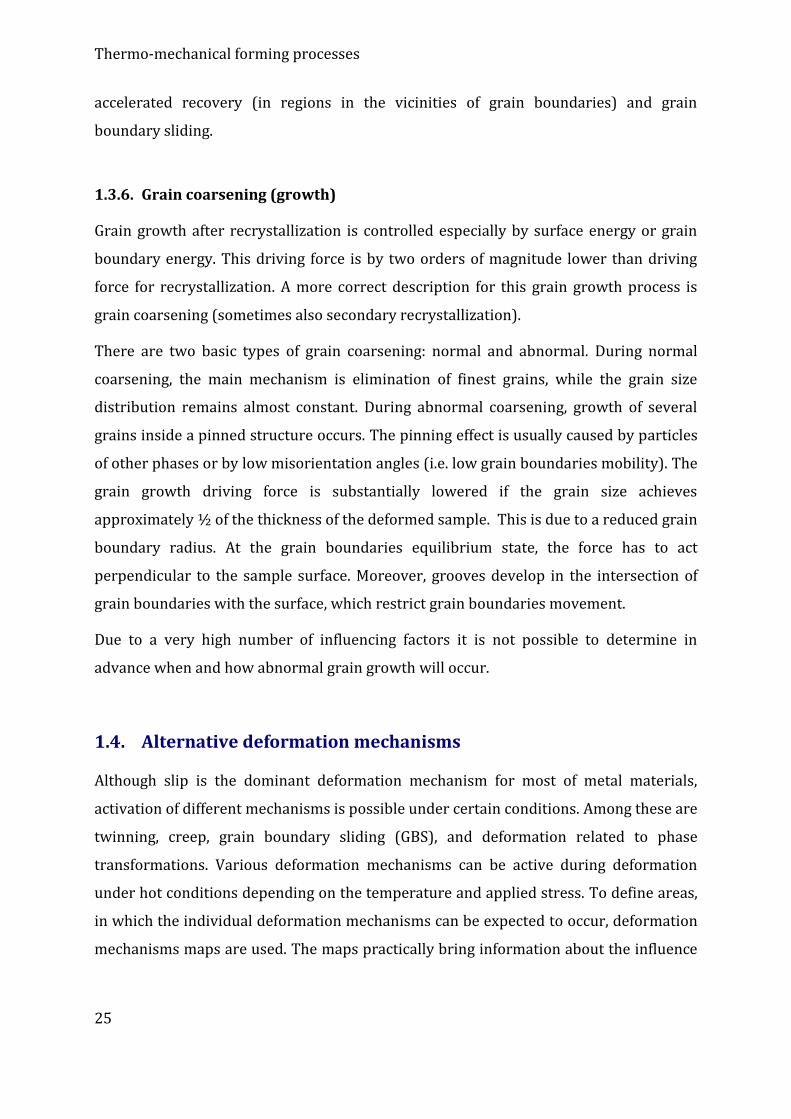
mechanism. An example of such a map is shown in Figure 8.
Figure 8: Deformation mechanisms map for W (grain size 10 m). [1]
The upper boundary of the diagram is created by theoretical shear stress. This is stress
that should be applied in a case of perfect deformation of crystals with no defects by
mutual collective translation of crystal planes. Deformation proceeds via dislocations
movement in their slip planes, which is supported by high temperature, i.e. by the
process of dynamic recovery caused by cross-slip and climb.
In the lower part of the map, creep region can be observed. This region can further be
divided into various sub-regions, each of which is characterized by a creep sub-
mechanism. Creep can be caused by dislocation movement or diffusion. Diffusion creep
has two types, Nabarro and Coble creeps. Twinning can also be mentioned among
deformation mechanisms occurring under these conditions. However, it is typical only
for several materials - twinning, as well as GBS, are not included in Figure 8. The reason
for neglecting GBS is since GBS in polycrystalline materials is usually enabled by
diffusion creep. Therefore GBS is already included inside the deformation maps diffusion
creep areas. GBS also occurs during superplastic forming since it is supported by very
fine grain size and elevated temperatures.
A concrete example can be tungsten, which deforms by diffusion creep and the strain
rate of 10-9 s-1 at the temperature of 1560°C and a relatively low stress of 10 MPa. This
Page 27
Thermo-mechanical forming processes
27
means that a deformation of 10% would take 3 years, which is very important
information for certain applications. On the other hand, at the stress of 100 MPa, the
material will deform by dislocation creep and the strain rate of 10-6 s-1. At the stress of
1000 MPa, the casual dislocation slip will dominate and the strain rate will be 0.1-10 s-1.
There is a presupposition that high-temperature dislocation creep is not different from
mechanisms occurring during conventional deformation under hot conditions.
1.4.1. Creep
Creep can be characterized as a deformation response of a material to long-time loading.
It comprises continuous elongation terminated by fracture. Creep is typical for high
temperatures, it occurs at low strain rates and relatively low stresses. Creep
deformation curve can be divided into three stages:
Stage 1 – primary creep
When a load is applied, a material is deformed and new dislocations are generated. The
dislocations then make obstacles in movement for each other, which causes decrease in
creep rate (Eq. 6)
dt/d 0 (6)
Stage 2 – secondary creep (steady-state creep, creep at constant rate)
In this area, strain hardening rate and dynamic recovery rate are equal. A constant load
is applied, which results into a constant strain rate after a certain time period.
Stage 3 – tertiary creep
Voids develop in the material, which causes increase in effective stress and also creep
rate. Voids growth quickly results into material fracture.
At low temperatures, strain hardening is dominant and the steady-state stage is usually
not reached. At high temperatures or high stresses, development of first voids can occur
even during the first stage, i.e. steady-state stage is either very short, or completely
missing.
Creep mechanisms
1. Diffusion creep
Page 28
Thermo-mechanical forming processes
28
During loading of a material (plastic deformation) the material tries to deform via
movement of vacations through a crystal along its boundaries. Therefore the
deformation proceeds by a creation of vacancies on these boundaries due to tensile
stresses. At the same time, destruction of vacancies on boundaries by the influence of
compression stresses occurs. This can be expressed by Eq. 7.
v
bv
DD
DD
kTD
114
2
0 (7)
where is atom volume, D is grain size, Db, Dv are diffusion coefficients for volume and
grain boundaries diffusion, respectively, is grain boundaries area effective for grain
boundaries diffusion.
This equation assumes that ancillary processes of nucleation and annihilation at grain
boundaries and GBS require a similar negligible energy and stress. However, if this
condition is not met and volume diffusion dominates, Nabarro or Nabarro-Herring creep
occur. Contrariwise, Coble creep occurs in cases of dominant diffusion at grain
boundaries.
2. Dislocation creep
If a stress higher than corresponding to the diffusion creep region in a deformation map
is applied, another deformation mechanism is activated. Although deformation is
realized via dislocation slip and climb, diffusion is a process controlling dislocations
recovery by climbing. Depending on the temperature and stress, four main groups of
dislocation creep mechanism can be distinguished.
1 – slip and climb controlled by volume diffusion
2 – slip and climb controlled by pipe diffusion
3 – Harper-Dorn creep
4 – power law breakdown
The first two mechanisms can be characterized using the power law relation (Eq. 8).
n
b
GkT
GbDA
0 (8)
For higher stresses, the following energetic dissolution relation is valid (Eq. 9).
Page 29
Thermo-mechanical forming processes
29
expK0 (9)
A linear dependence between stress and strain rate - Harper-Dorn creep - applies for
some materials.
1.4.2. Grain boundary sliding and superplasticity
Superplasticity is an ability of crystalline materials to extremely plastically deform when
subjected to tensile stress. The elongation is usually on the order of several hundred
percent. Superplasticity in most cases occurs at high temperatures and low strain rates,
while the necessary stress is rather low (to 20 MPa). Although this phenomenon has
already been widely studied, its application is still limited due to the requirement of very
low strain rates. Applicability of superplastic forming is therefore especially for
fabrication of components with complex shapes and with limited production capacities,
which can be for example specific components for aerospace industry.
Several types of superplasticity can be distinguished. One of them is superplasticity of
fine-grain structures, since fine grains are among the necessary conditions for this type
(GBS is the main mechanism). Besides, there are transformation superplasticity,
superplasticity induced by inner stresses and superplasticity at high strain rates
(hyperelasticity).
During GBS, mutual sliding of two grains occurs due to shear stress. In contrast to
dislocation slip during which grains get elongated in the direction of deformation, grains
more or less maintain their dimensions during GBS. For superplasticity forming GBS is
the entirely dominant mechanism. During GBS, cavities form in the regions where grains
slide along each other. It is therefore clear that during superplastic forming a
mechanism providing time suppressing (delaying) of cavities development has to be
active. To enable continuation of sliding, the material has to be shifted (usually by
diffusion creep) from regions where grains overlap (regions subjected to compression
stress) to regions with tendencies to create voids (regions subjected to tensile stress).
Page 30
Thermo-mechanical forming processes
30
Conditions of superplasticity
The first condition of superplastic forming for ultra-fine grained materials is the
condition of high m (strain rate sensitivity) coefficient value, which is usually defined by
Eq. 10 for a concrete deformation temperature.
),T(log/log 0 (10)
High values of m minimalize formations of necks during tensile tests (i.e. localization of
deformation), expected in the absence of strain hardening. The only possible mechanism
of strain hardening during diffusion creep GBS is grain coarsening.
The second condition is an increase in temperature to a sufficient value. The critical
value is usually a temperature higher than half of the melting temperature of the
particular material.
The third condition is the already mentioned strain rate (usually to 10-2 s-1, preferably
lower). Mathematically it can be described by Eq. 11.
m)(k 0 (11)
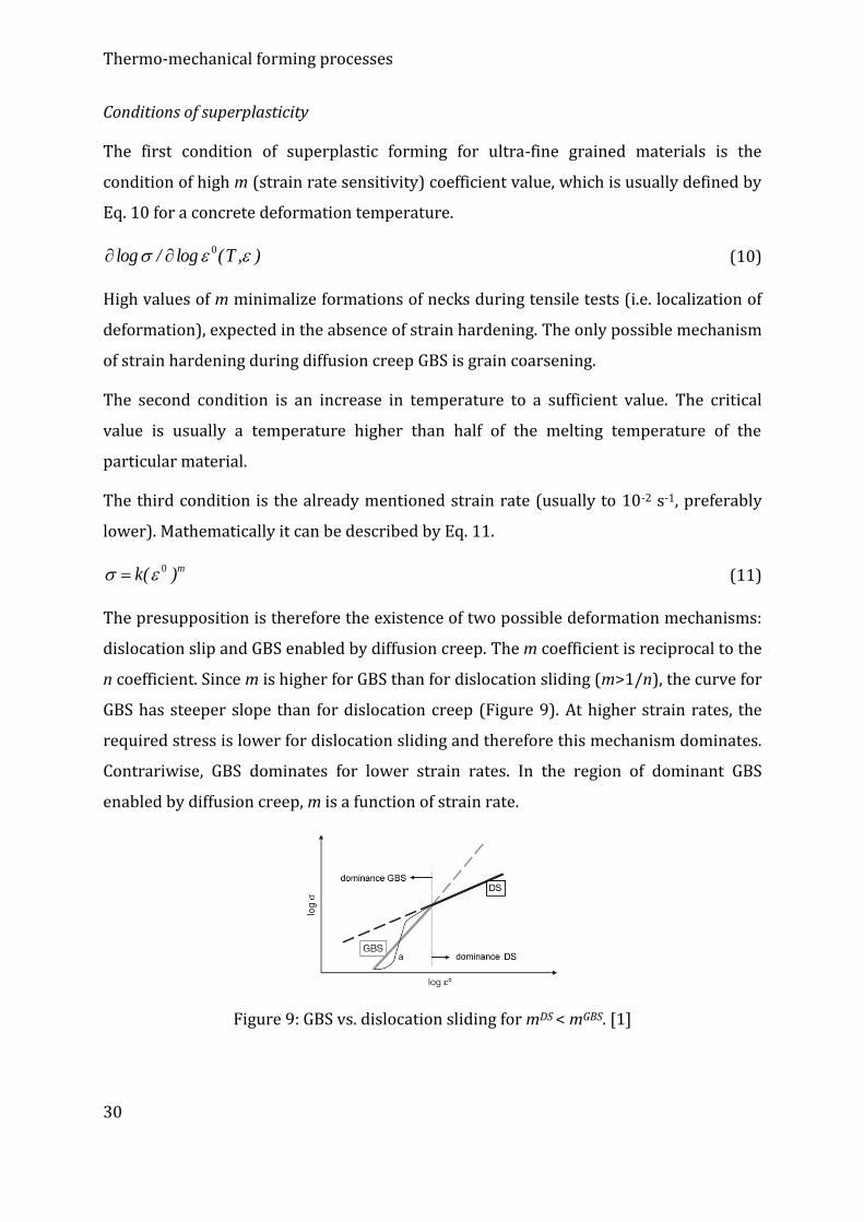
The presupposition is therefore the existence of two possible deformation mechanisms:
dislocation slip and GBS enabled by diffusion creep. The m coefficient is reciprocal to the
n coefficient. Since m is higher for GBS than for dislocation sliding (m>1/n), the curve for
GBS has steeper slope than for dislocation creep (Figure 9). At higher strain rates, the
required stress is lower for dislocation sliding and therefore this mechanism dominates.
Contrariwise, GBS dominates for lower strain rates. In the region of dominant GBS
enabled by diffusion creep, m is a function of strain rate.
Figure 9: GBS vs. dislocation sliding for mDS < mGBS. [1]
Page 31
Thermo-mechanical forming processes
31
The fourth condition describes the grain size, which should be between 1 and 10 m.
However, the influence of grain size is different for both the mechanisms. Decreasing
grain size increases the size of GBS and superplasticity regions at the expense of
dislocation sliding regions. This is one of the reasons for preparation of UFG materials,
which could enable high-speed superplasticity forming.
The fifth condition is the presence of fine dispersed secondary phase particles with sizes
comparable to the grain size. This suppresses grain growth at low strain rates and high
deformation temperatures.
The sixth condition relates to the grain boundaries. These enable easy sliding during
superplastic forming and can also act as sources and storages of vacancies. However, it
is still not clear how these relate to superplasticity. It was found that HAGBs support
GBS significantly more than LAGBs. On the other hand, voids develop more often in
regions with HAGBs, than with LAGBs. Consequently, material failure develops in a case
of their coalescence into networks. However, not only the frequency of their occurrence
is of influence, but also the character of grain boundaries distribution. Moreover,
likewise for recrystallization and grain growth, certain CSL boundaries are especially
important for the probability of GBS to develop. Small voids develop on grain
boundaries (triple points, precipitates). Due to continuing deformation they
subsequently grow and eventually mutually adhere, which result into a macroscopic
failure. The character of boundaries is very important during this process.
Most of the known materials can be subjected to superplastic forming. Among the most
important are many eutectic alloys, Fe-based and Ti-based alloys and many Al-based
alloys (supral, Al-Zn-Mg, AlMgMn etc.).
1.5. Kinetics of structure-modifying mechanisms
1.5.1. Influence of microalloying elements
Microalloying elements very effectively delay softening processes not only by their
presence in solid solution, but especially if present in fine dispersed precipitates. The
most effective are precipitates smaller than 5 nm segregated mostly on subgrain
boundaries. Since precipitates usually coarsen at higher temperatures (approx. 1,000°C),
Page 32
Thermo-mechanical forming processes
32
they lose their influence on the softening processes kinetics. The most significantly delay
softening processes the following elements (from the most to the least effective): Nb-Ti-
Al-N. Niobium is effective up to 0.04%, titanium from 0.10 to 0.15%. Higher contents of
Nb and Ti do not substantially influence their effect.
Due to the delaying effect of microalloying elements, recrystallization is suppressed and
recovery is the dominant softening mechanism at lower temperatures to strains of
approximately 0.6 - 0.7. Dynamic recovery occurs at high temperatures together with
dynamic recrystallization, which is the dominant mechanism around the temperature of
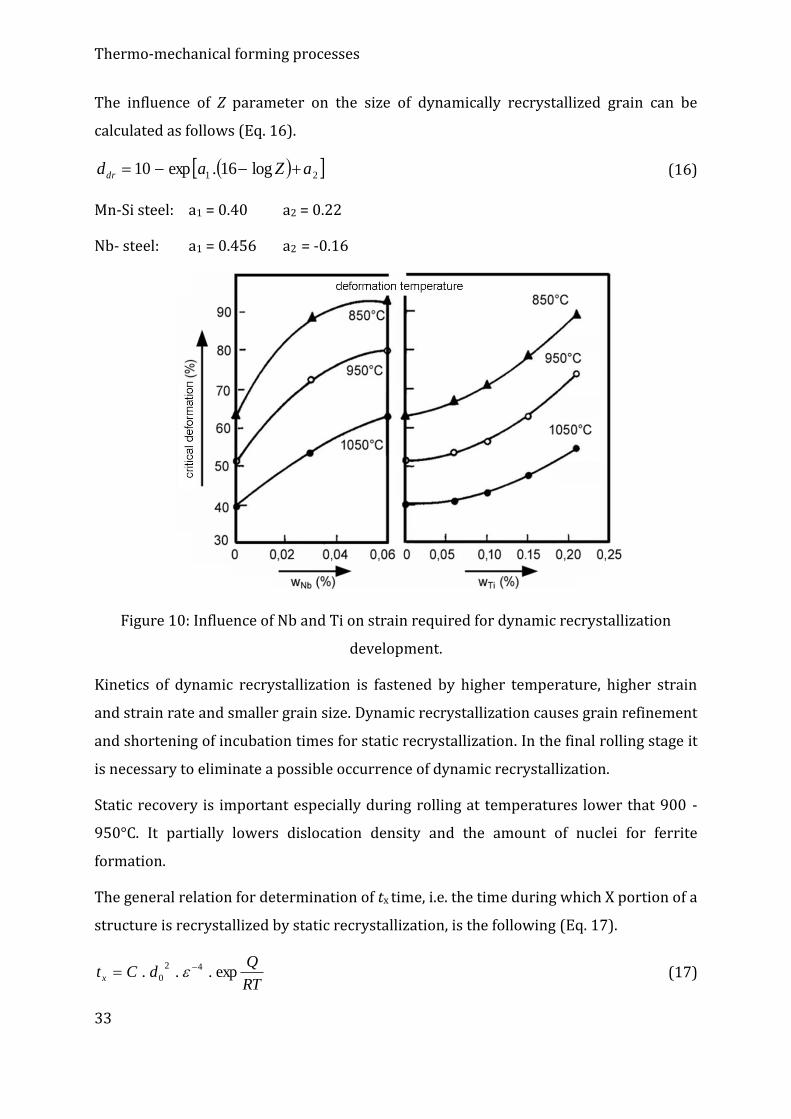
950 - 1,000°C. The influences of Nb and Ti on strain required for development of
dynamic recrystallization are shown in Figure 10. When content of Nb is approx. 0.04%,
dynamic recrystallization cannot be expected in the final rolling stage at temperatures
below 900°C (stage 2).
Critical strain value for development of dynamic recrystallization pik can be expressed
by Eq. 12.
nm
pik dZA 0.. (12)
where A, m, n are constants.
After their computation can Eq. (12) be depicted as follows (Eq. 13).
415021
0 1094 .Z.d., ,/
pik (13)
The influence of microalloying elements in solid solution on dynamic recrystallization
delay can be expressed by soluble retardation parameter (SRP) (Eq. 14).
100..
1,0.log
xatt
tSRP
ref
x (14)
where tref , tx are times required for development of dynamic recrystallization in a
reference steel, and in a steel containing x element.
With increasing strain rate, the microalloying element effect increases as well (Eq. 15).
2
121 log.
e
eeSRPeSRP
(15)
Page 33
Thermo-mechanical forming processes
33
The influence of Z parameter on the size of dynamically recrystallized grain can be
calculated as follows (Eq. 16).
21 log16.exp10 aZaddr (16)
Mn-Si steel: a1 = 0.40 a2 = 0.22
Nb- steel: a1 = 0.456 a2 = -0.16
Figure 10: Influence of Nb and Ti on strain required for dynamic recrystallization
development.
Kinetics of dynamic recrystallization is fastened by higher temperature, higher strain
and strain rate and smaller grain size. Dynamic recrystallization causes grain refinement
and shortening of incubation times for static recrystallization. In the final rolling stage it
is necessary to eliminate a possible occurrence of dynamic recrystallization.
Static recovery is important especially during rolling at temperatures lower that 900 -
950°C. It partially lowers dislocation density and the amount of nuclei for ferrite
formation.
The general relation for determination of tx time, i.e. the time during which X portion of a
structure is recrystallized by static recrystallization, is the following (Eq. 17).
RT
QdCt x exp... 42
0
(17)
Page 34
Thermo-mechanical forming processes
34
For Nb-V steels, the following relation counting with the influence of thermomechanical
parameters and grain size was derived (Eq. 18)
RTQdZCt Rx /exp....2
0
48/3 (18)
For < cr: C = 3.54·10-21, QR = 480 kJ·mol-1
Grain size after static recrystallization:
Mn-Si steel: 167,0
0 .. dDdrex (19)
Nb steel: 671,067,0
0
| .. dDdrex (20)
The relations are valid for < cr and for Nb-steels for temperatures above 950 °C.
After static recrystallization is finished, further grain growth can be described as follows
(Eq. 21):
RTQtAdd ggrex /exp..|1010 (21)
where A| is constant, Qgg is activation energy for grain growth.
Grain growth kinetics is expressed by Eq. 22.
ntKd . (22)
where dy is austenitic grain size, t is time after recrystallization finish, K, n are constants.
1.5.2. Kinetics of static recrystallization
The basic model is the Avrami relation (23) expressing the portion of recrystallized
structure X as a function of time t. This equation provides a successful description of
recrystallization curve on the basis of two parameters.
k
xt
tX
5,0
693,0exp1 (23)
The k exponent, which is between the values of 1 and 2, is usually not sensitive to
deformation parameters, whereas the time for 50% of recrystallized portion, depicted as
t0,5, changes in a wide range and depends on deformation conditions. It is therefore
Page 35
Thermo-mechanical forming processes
35
favorable to express the t0,5 value quantitatively in dependence on deformation
parameters changes.
The basic physical-metallurgical approach implies that the recrystallization kinetics
depends on the nuclei density, driving force for growth and grain boundaries mobility.
On the other hand, besides temperature, the theory cannot exactly define the influence
of other parameters. Therefore, an adjusted constitutive equation is usually used instead
of its physical form. For example, Eq. 24 was derived to determine the time of static
recrystallization start for a Nb-alloyed steel with Nb dissolved in solid solution (depicted
as t0,05x).
Nb
TRTdt x 185
10.75,2exp
300000exp10.75,6
542
0
20
05,0 (24)
This equation is valid when strain ε is lower than required for dynamic recrystallization
start. Its appearance is compatible with an equation derived for a C-Mn steel with 0.04%
Nb, original grain size d0 in μm and Nb content in wt. %. If k = 2, then t0,5x is equal to 0.27
t0,05x. The subsequent size of recrystallized grains drex is described using Eq. 25.
67,067,0
09,0 ddrex (25)
These empirical equations cannot be relied on completely, although there evidently is a
relation between Eqs. 24 and 25 (if grain growth during recrystallization is eliminated).
The number of nuclei in a unit volume Nv is then (Eq. 26):
343,0
rexv dN (26)
From the above mentioned is obvious that the influence of the original grain size on
kinetics of recrystallization according to Eq. 24 is physically dependent on nucleation,
since grain boundaries provide preferential locations for nucleation. The d02 dependence
is valid only if nucleation occurs only on boundaries. However, in reality boundaries
edges and mutual interaction of grains have to be taken into account as well. Likewise,
the ε-0,67 dependence in Eq. 25 depends on nucleation, for which no physical model has
been developed so far. Due to these facts, parabolic hardening leading to linear increase
in dislocation density with increasing strain and subsequently driving force for grain
boundaries migration is really expected. Considering that grain growth rate, driving
Page 36
Thermo-mechanical forming processes
36
force and nucleation are proportionally dependent only on grain boundaries, we get an
even more complicated dependence on time. Consequently, various researchers come to
various results of analyses even for the same types of steels. Nevertheless, all the
researchers consider the influence of strain, grain size and dwell temperature to be
substantial, although the strain rate and temperature in the Zenner-Hollomon
parameter vary (can be included due to its influence on dislocation density). As has
already been explained above, this has only a neglectable influence on t0,05x. The only
important difference between the different forms of the equations is the value of critical
strain – the limit up to which can be applied.
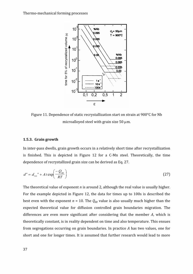
As was already pointed out, Eqs. 24 and 25 are valid only if strain is lower than critical
for dynamic recrystallization start. At such strains only small recrystallized grains
develop on the original grain boundaries, which are the most favorable locations for
nucleation of static recrystallization. However they provide only a small amount of
nuclei for dynamic recrystallization which occurs with continuing deformation. This
results into a decreasing limit strain for static (or metadynamic) recrystallization start,
as depicted in Figure 11.
The value of critical strain has been well investigated for C-Mn steels, but less for
microalloyed steels with Nb. This value is very important for determination of one of
three critical temperatures – temperature of zero recrystallization Tzr – at the absence of
precipitation. For example, if the dwell time between passes is 1s, then Tzr = 900°C for a
steel with 0.095% Nb. As was explained above (DRCF), there is a real possibility of
development of dynamic recrystallization by an accumulated deformation lower than εc
without a prior occurrence of static (metadynamic) recrystallization. Since εc depends
on Zenner-Hollomon parameter Z and grain size d0, it is obvious that when precipitation
do not occur the Tzr temperature depends on forming conditions, but also on chemical
composition, as depicted for a carbon steel for strain rates 1 to 100 s-1 (Figure 11).
Page 37
Thermo-mechanical forming processes
37
Figure 11. Dependence of static recrystallization start on strain at 900°C for Nb
microalloyed steel with grain size 50 m.
1.5.3. Grain growth
In inter-pass dwells, grain growth occurs in a relatively short time after recrystallization
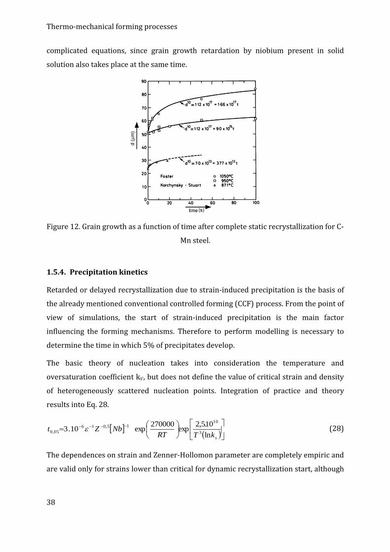
is finished. This is depicted in Figure 12 for a C-Mn steel. Theoretically, the time
dependence of recrystallized grain size can be derived as Eq. 27.
d d AtQ
RTn
rex
n gg
exp (27)
The theoretical value of exponent n is around 2, although the real value is usually higher.
For the example depicted in Figure 12, the data for times up to 100s is described the
best even with the exponent n = 10. The Qgg value is also usually much higher than the
expected theoretical value for diffusion controlled grain boundaries migration. The
differences are even more significant after considering that the member A, which is
theoretically constant, is in reality dependent on time and also temperature. This ensues
from segregations occurring on grain boundaries. In practice A has two values, one for
short and one for longer times. It is assumed that further research would lead to more
Page 38
Thermo-mechanical forming processes
38
complicated equations, since grain growth retardation by niobium present in solid
solution also takes place at the same time.
Figure 12. Grain growth as a function of time after complete static recrystallization for C-
Mn steel.
1.5.4. Precipitation kinetics
Retarded or delayed recrystallization due to strain-induced precipitation is the basis of
the already mentioned conventional controlled forming (CCF) process. From the point of
view of simulations, the start of strain-induced precipitation is the main factor
influencing the forming mechanisms. Therefore to perform modelling is necessary to
determine the time in which 5% of precipitates develop.
The basic theory of nucleation takes into consideration the temperature and
oversaturation coefficient ks,, but does not define the value of critical strain and density
of heterogeneously scattered nucleation points. Integration of practice and theory
results into Eq. 28.
skTRTNbZt
ln
10.5,2exp
270000exp10.3
3
1015,016
05,0 (28)
The dependences on strain and Zenner-Hollomon parameter are completely empiric and
are valid only for strains lower than critical for dynamic recrystallization start, although
Page 39
Thermo-mechanical forming processes
39
they are physically just. Especially implementation of parameter Z instead of simple
strain rate is a contribution to a reliable solution of the equation.
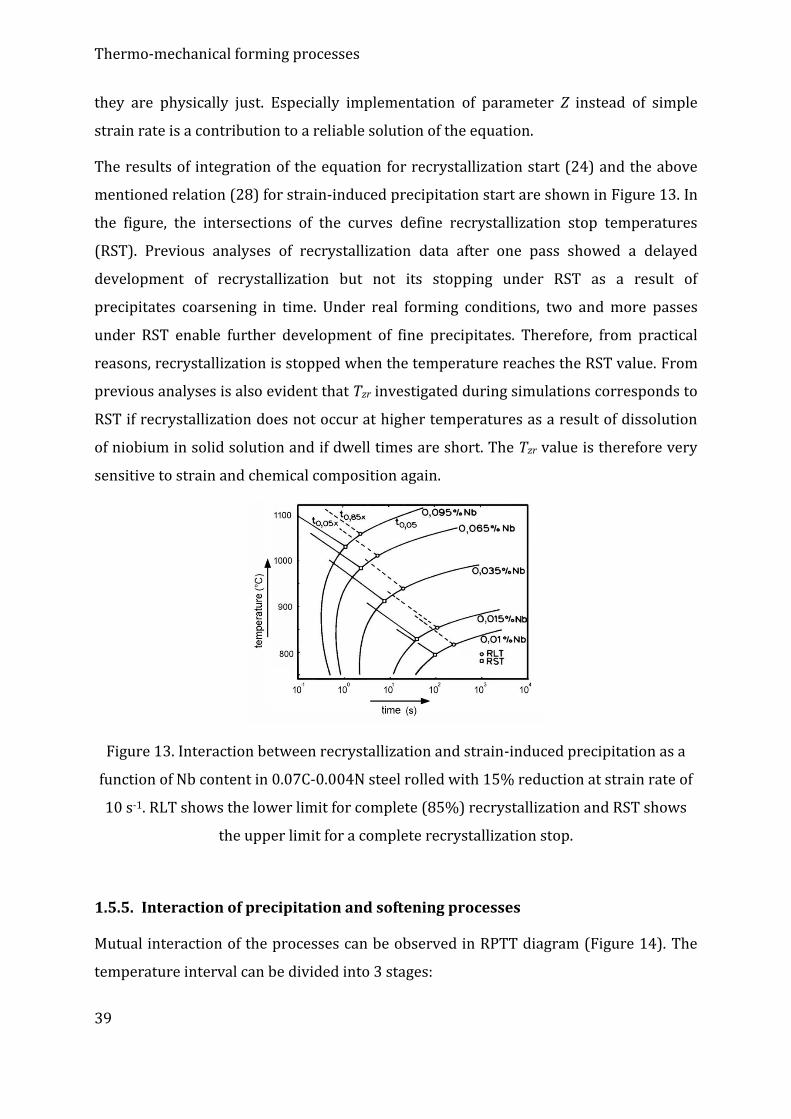
The results of integration of the equation for recrystallization start (24) and the above
mentioned relation (28) for strain-induced precipitation start are shown in Figure 13. In
the figure, the intersections of the curves define recrystallization stop temperatures
(RST). Previous analyses of recrystallization data after one pass showed a delayed
development of recrystallization but not its stopping under RST as a result of
precipitates coarsening in time. Under real forming conditions, two and more passes
under RST enable further development of fine precipitates. Therefore, from practical
reasons, recrystallization is stopped when the temperature reaches the RST value. From
previous analyses is also evident that Tzr investigated during simulations corresponds to
RST if recrystallization does not occur at higher temperatures as a result of dissolution
of niobium in solid solution and if dwell times are short. The Tzr value is therefore very
sensitive to strain and chemical composition again.
Figure 13. Interaction between recrystallization and strain-induced precipitation as a
function of Nb content in 0.07C-0.004N steel rolled with 15% reduction at strain rate of
10 s-1. RLT shows the lower limit for complete (85%) recrystallization and RST shows
the upper limit for a complete recrystallization stop.
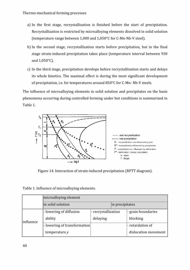
1.5.5. Interaction of precipitation and softening processes
Mutual interaction of the processes can be observed in RPTT diagram (Figure 14). The
temperature interval can be divided into 3 stages:
Page 40
Thermo-mechanical forming processes
40
a) In the first stage, recrystallization is finished before the start of precipitation.
Recrystallization is restricted by microalloying elements dissolved in solid solution
(temperature range between 1,000 and 1,050°C for C-Mn-Nb-V steel).
b) In the second stage, recrystallization starts before precipitation, but in the final
stage strain-induced precipitation takes place (temperature interval between 930
and 1,050°C).
c) In the third stage, precipitation develops before recrystallization starts and delays
its whole kinetics. The maximal effect is during the most significant development
of precipitation, i.e. for temperatures around 850°C for C-Mn- Nb-V steels.
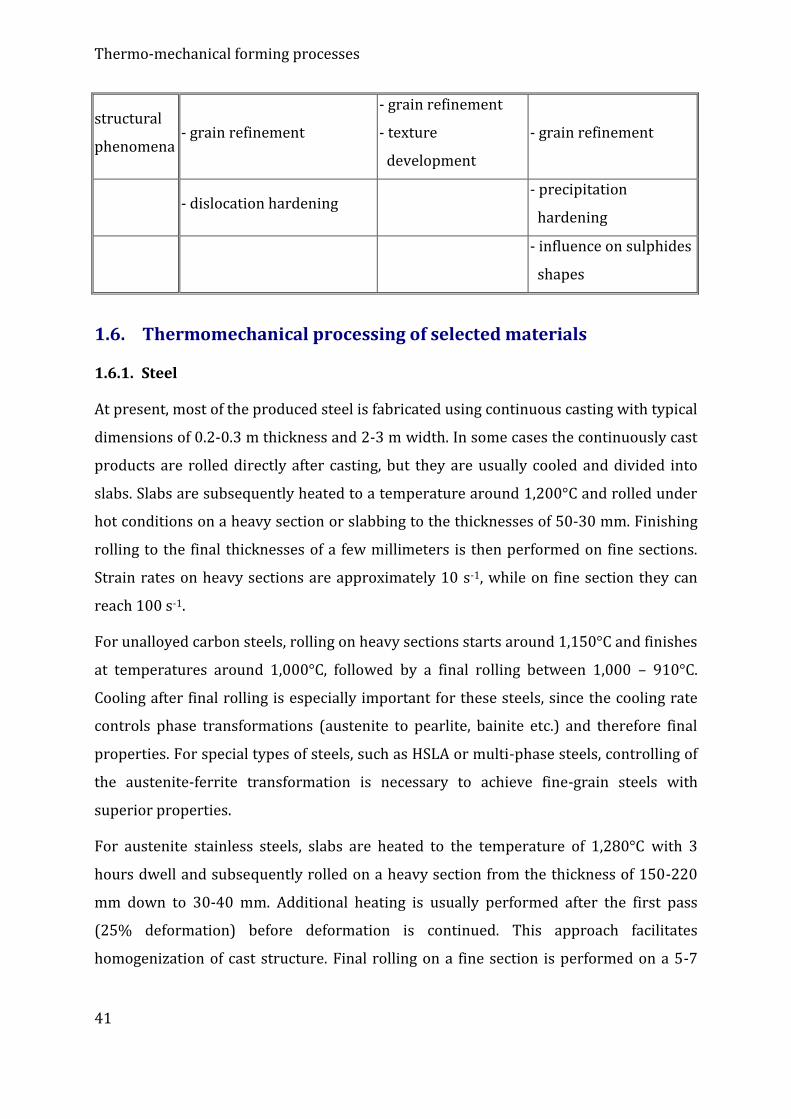
The influence of microalloying elements in solid solution and precipitates on the basis
phenomena occurring during controlled forming under hot conditions is summarized in
Table 1.
Figure 14. Interaction of strain-induced precipitation (RPTT diagram).
Table 1. Influence of microalloying elements.
microalloying element
in solid solution in precipitates
influence
- lowering of diffusion
ability
- recrystallization
delaying
- grain boundaries
blocking
- lowering of transformation
temperature y
- retardation of
dislocation movement
Page 41
Thermo-mechanical forming processes
41
structural
phenomena - grain refinement
- grain refinement
- texture
development
- grain refinement
- dislocation hardening - precipitation
hardening
- influence on sulphides
shapes
1.6. Thermomechanical processing of selected materials
1.6.1. Steel
At present, most of the produced steel is fabricated using continuous casting with typical
dimensions of 0.2-0.3 m thickness and 2-3 m width. In some cases the continuously cast
products are rolled directly after casting, but they are usually cooled and divided into
slabs. Slabs are subsequently heated to a temperature around 1,200°C and rolled under
hot conditions on a heavy section or slabbing to the thicknesses of 50-30 mm. Finishing
rolling to the final thicknesses of a few millimeters is then performed on fine sections.
Strain rates on heavy sections are approximately 10 s-1, while on fine section they can
reach 100 s-1.
For unalloyed carbon steels, rolling on heavy sections starts around 1,150°C and finishes
at temperatures around 1,000°C, followed by a final rolling between 1,000 – 910°C.
Cooling after final rolling is especially important for these steels, since the cooling rate
controls phase transformations (austenite to pearlite, bainite etc.) and therefore final
properties. For special types of steels, such as HSLA or multi-phase steels, controlling of
the austenite-ferrite transformation is necessary to achieve fine-grain steels with
superior properties.
For austenite stainless steels, slabs are heated to the temperature of 1,280°C with 3
hours dwell and subsequently rolled on a heavy section from the thickness of 150-220
mm down to 30-40 mm. Additional heating is usually performed after the first pass
(25% deformation) before deformation is continued. This approach facilitates
homogenization of cast structure. Final rolling on a fine section is performed on a 5-7
Page 42
Thermo-mechanical forming processes
42
rolling stands tandem at temperatures between 1,000-1,100°C to the thicknesses of a
few millimeters (5-0.5), followed by annealing.
Conventional steels (Al killed)
The usual forming method for these steels consists of continuous casting of a slab, its
temperature levelling (1,200°C), hot rolling with the finishing temperature of 900°C,
coiling (under 600°C), cold rolling (reduction of 70-90%) and annealing (650-
700 °C/several hours). Rolled strips recrystallize during annealing and, at the same time,
precipitation of fine AlN particles occurs. During and after hot rolling, precipitation of
AlN must not occur since these precipitates would coarsen during the continuing
deformation and would not be further effective during annealing. Therefore, rapid
cooling down to temperatures around 600°C is advantageously performed after hot
rolling. At these temperatures, the product can be coiled since further cooling does not
result into precipitation of AlN. Contrariwise, if the material is heated too fast during
annealing, recrystallization occurs before precipitation of AlN (unwanted). The final
rolling temperature should be the lowest possible in the austenitic region (closely above
A3). This results into achievement of very fine grain sizes. Optimal reduction during cold
rolling should be selected considering chemical composition of the given steel. For most
cases it is around 70-90%. It is also necessary to enable post-recrystallization grain
growth.
Continuously annealed low-carbon steels
On continuous mills, strips are annealed at the heating rate of 10°C/s, annealing is
performed at relatively high temperatures but short times (1-5 min). Due to such a high
heating rate, recrystallization for cold rolled strips is faster than precipitation of AlN
particles. This is also the reason why a method similar to the one for conventional
annealing (i.e. filtration of recrystallization nuclei) cannot be applied and it is necessary
to apply a different mechanism.
The heating temperature before hot rolling has to be low (under 1,100°C) in order to
prevent massive dissolution of MnS and AlN. These particles can further coarsen during
hot rolling without significantly influencing material behavior during annealing.
Furthermore, coiling temperature should be sufficiently high (above 730°C) to enable
development of coarse carbides during slow cooling of the coil. On the contrary, heating
Page 43
Thermo-mechanical forming processes
43
rate during the final annealing should be sufficiently high (approx. 10°C/s) to prevent
massive diffusion of carbon atoms into the matrix. In most cases, high-temperature
annealing (up to 850°C) is used to enable grain growth after annealing.
Austenitic steels
A large number of phases can precipitate in austenitic steels during processing,
including sigma phase – an intermetallic phase usually containing 50% Cr and 50% Fe.
Sigma phase causes embrittlement and decrease in corrosion resistance. Although it is
thermodynamically very stable, it develops very slowly, which is favorable. For this
phase to occur, temperature around 600°C and time in the order of magnitude of years
are usually required. It typically develops around other precipitates and in locations
with high energies, such as triple points and grain boundaries. The development is
accompanied by a relatively complicated mechanism.
Due to precipitation, continuous recrystallization does not proceed. Development of
recrystallization is usually initiated by strain especially on deformed grain boundaries,
but other mechanisms (such as coalescence of subgrains and their growth) are probably
also important, especially in highly deformed locations. Sigma phase particles are not
necessary for recrystallization initiation. Coarser precipitates typically occur in the
vicinities of serrated boundaries, which proves the development of both the processes,
recrystallization and precipitation, although recrystallization is delayed. At lower
annealing temperatures, oversaturation increases until the start of precipitation after a
certain annealing time. Further development depends on recrystallization activation
energy.
In practice, occurring changes of chemical composition and dislocation density imply
that mutual interactions can occur in a relatively wide temperature interval. For
example, temperatures in the range of 700-800°C mean a very large and fast
precipitation of sigma phase, which is enabled by discontinuous recrystallization.
Interstitial free (IF steels)
Deep-drawing ability of IF steels is increased when the content of interstitial elements
(carbon, nitrogen) is decreased. A common IF steel contains 20-30 pm of carbon and 30-
40 ppm of nitrogen. Other interstitial elements are Ti and Nb.
Page 44
Thermo-mechanical forming processes
44
A problem for these pure steels is achievement of fine grains after hot rolling. A rolling
mill has to provide favorable conditions to ensure precipitation of carbonitrides during
hot rolling and prevent massive austenite growth. Final passes during hot rolling are
usually connected with large reductions at relatively low temperatures. The final rolling
temperature is low (around A3), annealing is performed at high temperatures (up to
850°C) due to low content of C.
Steels with higher strength
The requirements to decrease emissions and fuel consumption in automotive industry
make car producers to, among other, use steels with higher strengths. The main reason
for their usage is the possibility to decrease the robustness of individual components
while maintaining their properties. However, increase in strength is usually
accompanied by decrease in formability.
Steels with controlled phosphorus content
The first possibility to increase strength of an alloy is to increase the content of atoms in
solid solution. Elements such as P, Si and Mn can increase strength of steels.
Nevertheless, Si and Mn also significantly decrease formability. Regarding P, it is
necessary to maintain only a very low content (0.04-0.08 vol.%).
Microalloyed steels and HSLA (High Strength Low Alloy) steels
The second possibility of material strengthening is precipitation strengthening. This can
be achieved as a result of addition of a small amount of Nb and Ti carbides and
carbonitrides. Non-dissolved fine particles prevent austenite grains from growing
during hot rolling. In final passes, austenite does not recrystallize and grains get only
flattened as a result of continuing deformation. During subsequent cooling, many ferrite
nuclei from which fine ferrite grains subsequently develop are activated. This results
into a significant increase in strength.
BH (Bake Hardening) steels
The cooling rate after recrystallization annealing is relatively high in most rolling mills.
Therefore, carbon content after cooling is far higher than for equilibrium state.
Consequently, carbon atoms diffuse into dislocations, which subsequently blocks their
Page 45
Thermo-mechanical forming processes
45
movement (i.e. deformation aging occurs). For conventional steels, this oversaturation
by carbon is prevented via double step annealing. In the first step, a strip is annealed for
a few minutes above the temperature of 710°C and subsequently cooled down to 400°C.
In the second annealing step, the strip is homogenized for a few minutes and
subsequently cooled down to room temperature. For BH steels, the effort is to maintain
low carbon oversaturation at room temperature. During stamping of components for car
bodies, new dislocations are generated, the movement of which is subsequently during
painting at elevated temperatures blocked by carbon atoms. This increases strength by
approx. 50 MPa.
DP (Dual Phase) steels
DP steels are low-carbon steels with carbon content around 0.1%. They contain soft
ferrite and 10-20% of hard martensite. This is achieved using heating around 800°C, i.e.
in the dual phase region, and subsequent rapid cooling. During the annealing, a portion
of austenite transforms into ferrite. From transformed ferrite grains, carbon atoms
return back to the residual austenite. During subsequent rapid undercooling, this
carbon-rich austenite transforms into martensite. DP steels therefore combine high
strength and a good formability with a significant strain hardening.
After conventional hot and cold rolling, a strip is reheated to the dual phase region
(800°C). The structure consists of ferrite with 10-20% of austenite depending on
chemical composition. After annealing, a strip is rapidly cooled and austenite gets
transformed into martensite. For some types of steels, residual austenite can be present
in the structure even at room temperature. Strength of such steels can vary between 500
and 1,000 MPa.
TRIP (Transformation Induced Plasticity) steels
A subsequent research of DP steels resulted into the development of TRIP steels
containing ferrite, bainite and residual austenite. Their initial structure is similar to DP
steels. Similarly to DP steels, annealing in the dual phase region is performed as first.
During a second annealing (300-400 °C), the residual austenite is transformed into
bainite, but a portion of the austenite (5-10%) remains maintained in the structure.
Carbon content in the residual austenite is so high that the austenite stays metastable
even during cooling to room temperature. The presence of residual austenite is very
Page 46
Thermo-mechanical forming processes
46
important, since during subsequent cold rolling, this gradually transforms into
martensite. This is the so called TRIP effect.
In most cases TRIP steels are conventionally hot and cold rolled steels subsequently
annealed in two steps. TRIP steels feature high strengths (600-1,000 MPa) and a very
good plasticity (elongation of approx. 30%).
HSLA (High Strength Low Alloy) steels
Rolling of HSLA steels is performed in the austenitic region. If the forming temperature
stays above a certain level (temperature of zero recrystallization), austenitic grains
remain more or less equiaxed due to subsequent recrystallization periods in the dwell
times between the individual passes. During final hot rolling, transformation of austenite
to ferrite and partially pearlite occurs. Since most of the ferrite grains develop on the
original austenite grains boundaries, a finer austenite grain size results into a finer
ferrite. The initial heating temperature for a conventional rolling is between 1,200 and
1,250°C. However, it is difficult to prevent austenite grains from growing in this region.
Final rolling is performed at temperatures higher than Tzr in order to eliminate high
rolling forces due to strain hardening of the material resulting from the absence of
recrystallization.
The heating temperature for controlled rolling is limited due to the requirement on
grain growth prevention (1,100°C). Final rolling is then performed at temperatures
lower than necessary for recrystallization development. This results into development
of pancake structures with increased amounts of grain boundaries, i.e. higher amounts
of nucleation sites and consequently finer ferrite grains. Another result is also a higher
strain hardening in final passes, i.e. the necessity to apply higher deformation forces.
From this reason larger reductions are usually applied in first passes and lower ones in
final passes.
Accelerated cooling starts above the A3 temperature and continues to the temperature of
500°C. This activates another ferrite grains development inside original austenite grains
and contributes to a further ferrite grains refinement. Nevertheless, a rapid cooling can
result into a development of a certain portion of bainite. This implies a higher strength,
but lower ductility.
Page 47
Thermo-mechanical forming processes
47
ULCB (Ultra Low Carbon Bainitic) steels
Upper bainite in the form of laths or plates is formed at temperatures around 500°C and
very slow cooling rates. Lower bainite forms in the form of lentils or laths similar to
martensite due to ultra-low carbon content. Granular bainite forms at very slow cooling
rates. Martensitic austenite forms in the form of micro-islands at medium and low
cooling rates due to microsegregations. Increased mechanical properties are caused
especially by very small subgrains of bainitic ferrite developing at low transformation
temperatures. For this type of steels, the effect of secondary hardening due to
precipitation of Cu and austenite phase transformation is usually observed.
Highly-alloyed steels
Tool steels
In a low-tempered state they feature high strength and low ductility. During processing,
they are prone to development of quenching cracks and premature and retarded
fractures. The cause of these defects is coarse plates of martensite rapidly growing
during quenching. When they stop on obstacles, their phase effects initiate development
of microcracks. If a deformation is performed before quenching, martensitic needles get
refined. This is due to a decrease in mobility of austenite-martensite interfaces due to
the presence of dislocations and increase in martensite nucleation rate. It is assumed
that annihilation of dislocations does not occur before martensitic transformation.
Stainless steels
For these steels, strain hardening is used to increase yield strength above 400 MPa while
maintaining favorable plasticity. Hardening is achieved by final rolling in the region of
restricted recrystallization, i.e. under 950°C. Due to the presence of residual stresses and
their indirect influence on corrosion resistance, steels with an increased corrosion
resistance, i.e. steels with low carbon contents and highly-stabilized steels, are especially
suitable for this type of processing.
For special purposes, e.g. materials for nuclear plants components, austenite grain
refinement and fine precipitation of titanium carbonitrides are achieved via high strains
at temperatures lower than 1,050°C and stabilization annealing.
Page 48
Thermo-mechanical forming processes
48
1.6.2. Controlled rolling of microalloyed steels
Controlled rolling of microalloyed steels enabled to increase yield strength by 50-100%
in comparison with C-Mn St52 type steels, while maintaining ductility down to -50°C and
maximum carbon equivalent Cc 0.45. The main influencing elements are C, Mn, Si, Mo, S,
Al, Nb, and V.
Basic parameters of controlled rolling
Heating temperature of slabs is between 1,050 and 1,200°C, depending on solubility of
carbonitrides. Its selection is made also regarding the required final rolling temperature.
Decrease in the heating temperature by 100°C results into up to 8% energy savings.
Heating time of slabs should ensure sufficient dissolution of Nb(CN), i.e. min. 0.02% Nb
in solid solution and uniform not-coarsened austenitic grains (150 to 200 m). Heating
time is longer than for Mn-Si steels, usually 5 to 8 minutes for 1 cm of slab thickness.
Rolling stage I (pre-rolling)
The total strain is 0.6 to 0.8 with individual thickness reductions of min. 0.15. The
temperature of the first rolling stage end is usually 50 to 150°C lower than the heating
temperature. At temperatures higher than 1,000°C the danger of grain growth occurs,
while at temperatures lower than 950°C austenite recrystallization does not develop
entirely. Optimal are temperatures around 1,000°C and higher strains in final passes.
Cooling before rolling stage II - work-piece, the thickness of which is at least 3x higher
than its final thickness, is cooled from the temperature of approx. 1,000°C to the initial
temperature of stage II. After excluding recrystallization, this temperature should not
exceed 900°C. Accelerated cooling decreasing precipitation of Nb(CN) is advantageous.
The cooling time depends especially on the work-piece thickness.
Rolling stage II
The total strain is between 0.6 and 0.7, advantageous are strains > 0.7. The final
rolling temperature depends especially on the required final mechanical properties and
deformation resistances. After reaching the yield strengths of 450 - 500 MPa, final
rolling temperatures decrease to 700 to 750°C.
Page 49
Thermo-mechanical forming processes
49
Recently, USA and Japan have developed dual-phase steels. Their development was
enabled especially by continuous annealing furnaces with accelerated cooling. Their
structure feature ferrite and islands of martensite or bainite. They can be produced
either by annealing after rolling in and region and subsequent cooling, or by hot
rolling of strips with subsequent rapid cooling.
SHT (Sumitomo High Toughness) process
The process is suitable for production of thick plates from constructional weldable
steels. It uses four basic principles to increase mechanical properties.
- grain size refinement, precipitation hardening, strain hardening, transformation
hardening
For the SHT process the mentioned requirements are met by a four-step mechanism:
- grain refinement by heating close above Ac3 temperature
- grain refinement by rolling in the region of austenite recrystallization
- deformation in the region of non-recrystallized austenite
- grain refinement by dynamic recovery or recrystallization of ferrite formed in the
dual-phase region
The SHT process consists of heating to the temperature of 1,150°C, rolling with
subsequent cooling of the work-piece on air under the Ar1 temperature, rolling with a
total reduction over 60%, final rolling at the temperature of approx. 700°C and
subsequent cooling on air.
The structures of plates produced by SHT feature fine and homogenous grains.
Increased ductility at lower temperatures and improved weldability imply their
application especially for lower temperatures and enables 2-3% saving of nickel.
1.6.3. Controlled rolling and controlled cooling
The disadvantage of controlled rolling is high rolling forces at lowered final rolling
temperatures and the required interpass dwells decreasing the efficiency of rolling mills.
Controlled cooling after rolling can be applied to achieve:
Page 50
Thermo-mechanical forming processes
50
- ferrite grains refinement
- pearlite or bainite refinement
- increase in final rolling temperatures
- improvement of weldability by decreasing of carbon equivalent Ce
Since plastic deformation influences temperatures and kinetics of phase transformations
it is necessary to know the particular ARA-diagrams. For structures after controlled
cooling, the cooling rate during phase transformations and stop temperature (tstop), at
which cooling is interrupted, are critical. Accelerated cooling should not be performed
till the end of a phase transformation to prevent massive occurrence of quenched
structures. For C-Mn-Nb-V steels, the optimum stop temperature is around 550°C. The
final structure consists of fine ferrite with uniformly scattered island of bainite. Fine
ferrite structure with pearlite in texture arrangement can be achieved only by controlled
rolling. For C-Mn-Nb steels, the optimum cooling rates are 10 to 15 K/s.
At the same final rolling temperatures, the differences in Re between processing by
controlled rolling (CR) and controlled rolling with subsequent controlled cooling
(CR+CC) can reach 50 MPa. For examples, the same Re values can be achieved at final
rolling temperatures of 700°C (CR) and 850°C (CR+CC).
Hardening achieved during controlled cooling is especially due to
- ferrite grain refinement, precipitation hardening and bainitic hardening
Determination of Re increase and change in transformation temperature can be made as
follows (Eq. 29 and Eq. 30):
PRe dKR 2/1. (29)
BBPRTR fKdKT .. |2/1 (30)
where K, K are coefficients expressing grain refinement in the Hall-Petch relation, d is
ferrite grain size, KB, fB are hardening coefficients of bainite and the portion of bainite in
structure, PR is strain increment from precipitation hardening, β, α are correction
coefficients.
Page 51
Thermo-mechanical forming processes
51
1.6.4. Aluminum and its alloys
Most of the Al products is produced by the method of direct solidification into castings
with thicknesses of 0.4-0.6 m, widths of 2 m and lengths of 9 m (i.e. weights of 20-30
tons). The castings are at first homogenized at the temperature of 500-600°C for a
relatively long time (several hours) in order to eliminate segregations and non-
equilibrium low-melting eutectics. This facilitates subsequent processing and increases
inhomogeneity. Annealing can influence the final structure in various ways, e.g.
especially for Cr, Mn, Zr containing alloys precipitation reactions during which dispersed
particles develop can occur.
After homogenization, an ingot is usually rolled on a reversible rolling stand to a plate of
30-10 mm thickness. The number of passes is 9-25. After hot rolling, i.e. before cold
rolling, the strip is coiled or, on modern mills, further hot rolled on a tandem. In practice,
a tandem mill has 2-6 stands. Cold rolling is usually performed using quarto stands with
two coil boxes, on which rolling to thicknesses of 15-20 μm is performed. For even
thinner foils (6 μm) the foils are doubled and further rolled. Interpass annealing is
necessary to enable large reductions without material failure.
At present, the technology of continuous strip casting is used for production of Al strips.
The thickness of the strips is usually 10-20 mm, due to which it is possible to directly
roll such strips in a tandem mill and therefore make the entire process more effective.
2. Controlled forming processes
Time to study: 10 hours
Aims After study of this chapter you will be able to
describe the principle of conventional controlled forming
Page 52
Thermo-mechanical forming processes
52
describe recrystallization controlled forming and define differences
between both the mentioned processes
describe dynamic recrystallization controlled forming
define interactions between recrystallization and stress-induced
precipitation
Lecture
2.1. Conventional controlled forming (CCF)
Stress-induced precipitation of Nb(CN) in steel requires approximately 10s. After
accumulation of a favorable amount of strain and occurrence of a certain volume
fraction of precipitates, austenitic structure of a pancake type develops. When the
stress-induced precipitation occurs faster than both the static and dynamic
recrystallizations, strengthening accumulates with every single pass and the mean
deformation resistance increases with increasing temperature. This results into high
deformation loads due to high dislocation densities. On the other hand, the resulting
microstructure consists of fine ferrite grains. This is caused by recrystallization of
austenite grains between passes, which is enabled since the flattened austenitic grains
before transformation have a high specific surface Sy.
2.2. Recrystallization controlled forming (RCF)
A carefully controlled recrystallization of austenite leads to a development of a fine
microstructure. This occurs at temperatures higher than 900°C, which is higher than for
CCF. Successful performance of this type of forming requires two basic factors. The first
one – recrystallization must not be too slow so that the required times are not too long.
This can be achieved by additions of V, or better Nb. Additions of V cause grain
refinement - decrease of grain boundaries mobility during recrystallization, although the
recrystallization is not entirely stopped. The second factor – grain growth must be
prohibited after each recrystallization cycle. Grain growth occurrence has a negative
Page 53
Thermo-mechanical forming processes
53
effect on the recrystallization grain refinement process under lower temperatures. For
this purpose 0.01% Ti can be added to support propagation of fine TiN particles during
cooling after continuous casting. When these particles are of a favorable size and
homogenous distribution, they can completely eliminate austenitic grain growth during
each recrystallization cycle.
2.3. Dynamic recrystallization controlled forming (DRCF)
An alternative form of recrystallization is dynamic recrystallization. This occurs in
cases for which the forming temperature is low and time between the individual passes
is too short for occurrence of a conventional recrystallization between passes. The
amount of precipitated carbides and nitrides is limited as well. Dynamic recrystallization
consists of nucleation and growth of new grains during deformation (contrary to the
afore-mentioned processes, for which these occurred after a deformation pass.) This
requires accumulation of a sufficient amount of deformation, i.e. usually real
deformation larger than 1, enabling a complete recrystallization of the microstructure
throughout the cross-section of the work-piece.
2.4. Interaction between recrystallization and stress-induced
precipitation
When static recrystallization occurs before precipitation, the conditions are favorable
for RCF. When precipitation occurs before static or dynamic recrystallization, the
conditions for occurrence of pancake structure are fulfilled and CCF can be performed.
Last but not least, DRCF is performed when dynamic recrystallization occurs before
precipitation.
The mechanism of ferrite grain refinement occurring in real processes can be
determined by a comparison of processes with a continuous precipitation during cooling
(CCP = Continuous Cooling Precipitation) in a dependence on temperature and time (see
Section 1.5.5). From such a dependence is evident that dynamic recrystallization can be
active as long as the final passes are within the times of 10s or shorter, i.e. before the
significant occurrence of stress-induced precipitation. This however requires no static
recrystallization during idle times between passes, but also accumulation of a significant
Page 54
Thermo-mechanical forming processes
54
amount of strain sufficient for a development of dynamic recrystallization, which
eventually forms the microstructure.
3. Modelling of thermo-mechanical forming
Time to study: 15 hours
Aims After study of this chapter you will be able to
describe the pros and cons of physical modelling – define the basic
condition of the process
define modelling using high-performance computers and appropriate
softwares, define algorithms of the used processes and perform their
evaluation
Lecture
3.1. Physical modelling of TMP
TMP is performed with the aim to increase physical properties of materials. Such
properties can be characterized with numerous tests, which are always standardized for
a selected material. The mostly used tests are tensile, compression and torsional. The
tests are usually performed at high temperatures in order to achieve strains and strain
rates similar to the real industrial conditions. However, one of the main practical
problems is the cooling rate after deformation, since the microstructure changes already
within a few seconds. In order to enable comparison of results of various deformation
tests performed under hot conditions, it is advantageous to evaluate them in the form of
a dependence of real stress and real strain (equivalent stress and strain).
Page 55
Thermo-mechanical forming processes
55
The reason for which classic tests are not used to test properties after TMP in real
conditions is above all the expenses. The casual devices are highly productive.
Therefore, modification of a production process or an implemented material
development process would be very ineffective. By this reason TMP is usually tested
under laboratory conditions.
Modelling has several advantages, among which is e.g. the possibility to investigate
tribological and geometrical deformation conditions. On the other hand, achievement of
the same conditions as in the real process is difficult. For example cooling conditions are
different for most of the processes. Moreover, high strain rates occurring in practice
cannot be achieved under laboratory conditions. By these reasons, it is advantageous to
perform simple laboratory material tests before a TMP is performed under real
production processing conditions. The result of such an approach is determination of the
influence of typical industrial conditions (temperature, deformation, strain rate, idle
times between passes, annealing times etc.). Such conditions are usually determined
using FE (finite element) simulations.
3.2 Computer modelling
The aim of computer modelling is to quantify the basic mechanisms influencing a
thermomechanical forming process, i.e. especially changes of temperature, strain, strain
rate and time, and implement them into general mathematic relations for industrial
forming processes. Modelling of microstructure is at present quite well developed in the
field of heat treatment of steels.
Considering possible examples of steel forming under hot conditions, it is evident
that the conditions for modelling are complex. A modelled forming process itself
consists of gradual deformation reductions, which are performed under defined velocity
and temperature conditions with defined dwell times between the individual reductions.
Modelling of such a process thus demands a multidisciplinary approach including
physical metallurgy, metallurgical engineering, mechanical engineering, applied
mathematics, mathematics and system engineering and so on. This is due to the fact that
a general model consists of several separate, however mutually integrated, sub-models.
Page 56
Thermo-mechanical forming processes
56
Task
Using the given values create a dependence of stress on strain. By means of exponential
regression derive a strengthening relation describing the created dependence.
This task is performed using MS Excel software. The values to be entered are
given in two columns – values of strain ε within the range of 0.01 – 1.5 with 0.01
step and corresponding values of stress. The data were experimentally obtained
using a torsional test. An example of the given values is shown in Table 2. These
values are further used to create a 2D dependence (point with smooth lines type).
Table 2 Example of the first 10 given stress and strain values
[-] 0.01 0.02 0.03 0.04 0.05 0.06 0.07 0.08 0.09 0.1
σ
[MPa] 217.56 226.02 231.12 234.80 237.70 240.10 242.14 243.93 245.51 246.94
The subsequent task is to create a strengthening relation for the stress-strain
dependence, i.e. an equation for calculation of stress depending on strain. This
equation can be acquired by clicking with the right mouse button on the curve in
the dependence and selecting addition of a trend line. From the line types it is
necessary to select exponential line, since the strengthening equation is of an
exponential type. The equation can further be shown in the created dependence
together with the correlation coefficient R2. The more the R2 value is close to 1,
the more precise is the description of the curve using the equation.
According to the regression analysis of MS Excel software, the strengthening
equation describing the curve is in the following form (55).
055025280 ,, (55)
In this case, the correlation coefficient is equal to 1. Check can be performed by
backwards calculations. It is necessary to write the final equation with a variable
value for deformation according to the given values into another column. The
checking calculation is shown in Table 3.
Page 57
Thermo-mechanical forming processes
57
Table 3 Example of the first 10 given stress and strain values
[-] 0.01 0.02 0.03 0.04 0.05 0.06 0.07 0.08 0.09 0.1
σ
[MPa] 271.56 226.02 231.12 234.80 237.70 240.10 242.14 243.93 245.51 246.94
The dependence created on the basis of the given stress and strain values,
together with the derived equation of exponential dependence and the
correlation coefficient, is depicted in Figure 15.
Figure 15: Dependence of stress (deformation resistance) on strain.
References
[1] HUMPHREYS, F.J., HARTLEY, M. Recrystallization and related annealing
phenomena. 2nd ed. Oxford: Pergamon; 1996, 617 p. ISBN 978-0080441641.
[2] VERLINDEN, B., DRIVER, J., SAMAJDAR, I., DOHERTY, D.R. Thermo-Mechanical
Processing of Metallic Materials, Pergamon Materials Series- series ed. R.W. Cahn,
Elsevier, Amsterdam, 2007, 332 p. ISBN 978-0-08-044497-0.
Page 58
Thermo-mechanical forming processes
58
[3] JONAS, J.J., SELLARS, C.M. Thermomechanical Processing. In Future developments
of Metals and ceramics. (Edited by J.A.Charles, G.W. Greenwood and G.C. Smith),
London Institute of Materials, 1992, 150 p., ISBN 09017-16030.
[4] WEISS, I., SEMIATIN, S.L. Thermomechanical processing of alpha titanium alloys-
an overview, Materials Science and Engineering A263, 1999, p. 243-256.