Využití indukovaného napětí pro detekci chyby operace elektromagnetického ventilu Karel Pospíšil, František Mach Katedra teoretické elektrotechniky Fakulta elektrotechnická Západočeská univerzita v Plzni [email protected], [email protected]Utilization of Induced Voltage for Fault Detection of Electromagnetic Valve Operation Abstract – The aim of this article is to describe a method for the sensorless fault detection of the electromagnetic valve operation. This method is based on the measurement of the voltage induced in the valve coil. Keywords – Electromagnetic valve; Fault operation; Induced voltage I. INTRODUCTION Electromagnetic valves are utilized as basic parts of a wide range of cyber-physical systems, ranging from the control elements in industrial applications or building automation to active safety elements in power systems. The important requirements for the state-of-the-art valves are: (i) high dynamic response, (ii) low energy consumption, (iii) operation safety, (iv) high reliability and (v) embedded intelligence. Therefore, our long-term research objective are novel concepts of electromagnetic actuator controlled by advanced model-based algorithms. The major goal of this research is to develop a sensorless fault detection method for linear electromagnetic actuators in the valve operation. Due to a wide utilization of electromagnetic actuators in many diverse industrial systems, this methodology can be used in a wide framework of industrial applications and systems. II. FORMULATION OF TECHNICAL PROBLEM The proposed method is designed for a prototype of the coaxial bistable electromagnetic valve with permanent magnets TROMAG [1], but it can be utilized for an arbitrary linear electromagnetic actuator. Figure 1 shows a schematic arrangement of the considered valve. Figure I. Schematic arrangement of bistable electromagnetic valve [1] Elektrotechnika a informatika 2018 [ 113 ]
Transcript
Využití indukovaného napětí pro detekci chyby operace elektromagnetického ventilu
Karel Pospíšil, František Mach Katedra teoretické elektrotechniky
Fakulta elektrotechnická Západočeská univerzita v Plzni
Utilization of Induced Voltage for Fault Detection of Electromagnetic Valve Operation
Abstract – The aim of this article is to describe a method for the sensorless fault detection of the electromagnetic valve operation. This method is based on the measurement of the voltage induced in the valve coil.
Keywords – Electromagnetic valve; Fault operation; Induced voltage
I. INTRODUCTION Electromagnetic valves are utilized as basic parts of a wide range of cyber-physical
systems, ranging from the control elements in industrial applications or building automation to active safety elements in power systems. The important requirements for the state-of-the-art valves are: (i) high dynamic response, (ii) low energy consumption, (iii) operation safety, (iv) high reliability and (v) embedded intelligence. Therefore, our long-term research objective are novel concepts of electromagnetic actuator controlled by advanced model-based algorithms. The major goal of this research is to develop a sensorless fault detection method for linear electromagnetic actuators in the valve operation. Due to a wide utilization of electromagnetic actuators in many diverse industrial systems, this methodology can be used in a wide framework of industrial applications and systems.
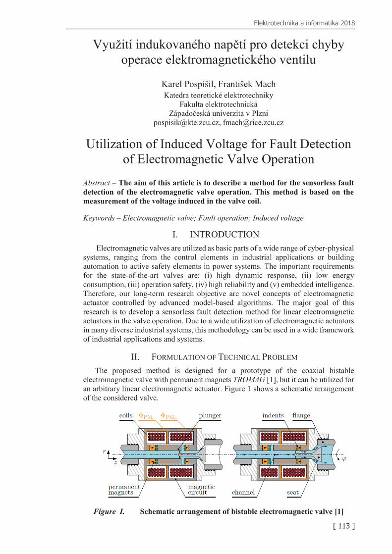
II. FORMULATION OF TECHNICAL PROBLEM The proposed method is designed for a prototype of the coaxial bistable
electromagnetic valve with permanent magnets TROMAG [1], but it can be utilized for an arbitrary linear electromagnetic actuator. Figure 1 shows a schematic arrangement of the considered valve.
Figure I. Schematic arrangement of bistable electromagnetic valve [1]
Elektrotechnika a informatika 2018
[ 113 ]
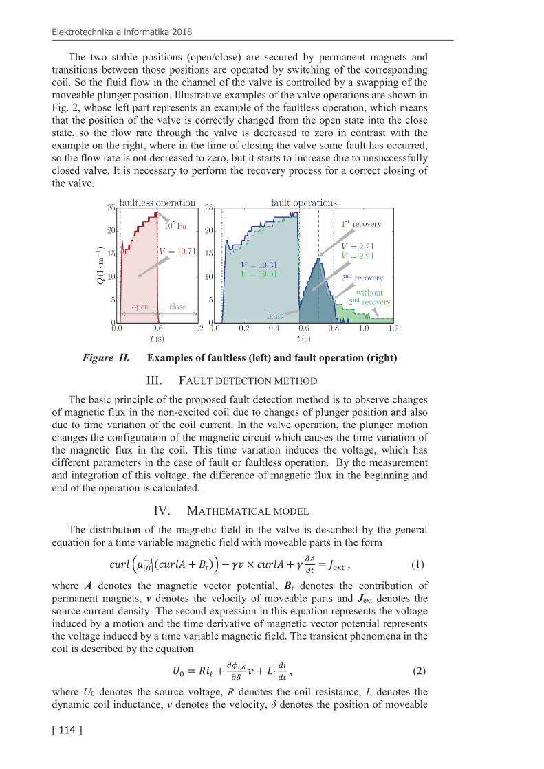
The two stable positions (open/close) are secured by permanent magnets and transitions between those positions are operated by switching of the corresponding coil. So the fluid flow in the channel of the valve is controlled by a swapping of the moveable plunger position. Illustrative examples of the valve operations are shown in Fig. 2, whose left part represents an example of the faultless operation, which means that the position of the valve is correctly changed from the open state into the close state, so the flow rate through the valve is decreased to zero in contrast with the example on the right, where in the time of closing the valve some fault has occurred, so the flow rate is not decreased to zero, but it starts to increase due to unsuccessfully closed valve. It is necessary to perform the recovery process for a correct closing of the valve.
Figure II. Examples of faultless (left) and fault operation (right)
III. FAULT DETECTION METHOD The basic principle of the proposed fault detection method is to observe changes
of magnetic flux in the non-excited coil due to changes of plunger position and also due to time variation of the coil current. In the valve operation, the plunger motion changes the configuration of the magnetic circuit which causes the time variation of the magnetic flux in the coil. This time variation induces the voltage, which has different parameters in the case of fault or faultless operation. By the measurement and integration of this voltage, the difference of magnetic flux in the beginning and end of the operation is calculated.
IV. MATHEMATICAL MODEL The distribution of the magnetic field in the valve is described by the general
equation for a time variable magnetic field with moveable parts in the form
where A denotes the magnetic vector potential, Br denotes the contribution of permanent magnets, v denotes the velocity of moveable parts and Jext denotes the source current density. The second expression in this equation represents the voltage induced by a motion and the time derivative of magnetic vector potential represents the voltage induced by a time variable magnetic field. The transient phenomena in the coil is described by the equation
𝑈𝑈0 = 𝑅𝑅𝑖𝑖𝜕𝜕 +𝜕𝜕𝜙𝜙𝑖𝑖,𝛿𝛿𝜕𝜕𝜕𝜕 𝛾𝛾 + 𝐿𝐿𝑖𝑖
𝑑𝑑𝑖𝑖𝑑𝑑𝜕𝜕 , (2)
where U0 denotes the source voltage, R denotes the coil resistance, L denotes the dynamic coil inductance, v denotes the velocity, δ denotes the position of moveable
Elektrotechnika a informatika 2018
[ 114 ]
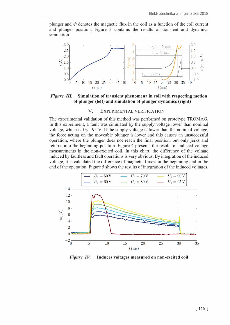
plunger and Φ denotes the magnetic flux in the coil as a function of the coil current and plunger position. Figure 3 contains the results of transient and dynamics simulation.
Figure III. Simulation of transient phenomena in coil with respecting motion
of plunger (left) and simulation of plunger dynamics (right)
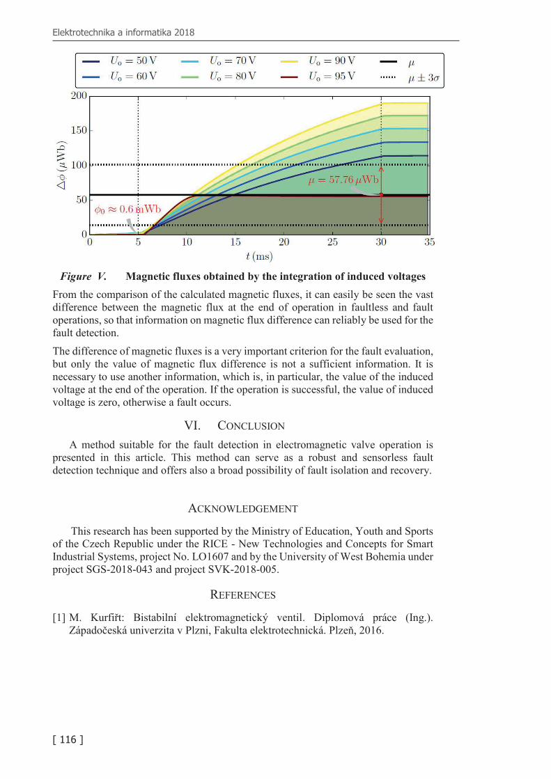
V. EXPERIMENTAL VERIFICATION The experimental validation of this method was performed on prototype TROMAG. In this experiment, a fault was simulated by the supply voltage lower than nominal voltage, which is U0 = 95 V. If the supply voltage is lower than the nominal voltage, the force acting on the moveable plunger is lower and this causes an unsuccessful operation, where the plunger does not reach the final position, but only jerks and returns into the beginning position. Figure 4 presents the results of induced voltage measurements in the non-excited coil. In this chart, the difference of the voltage induced by faultless and fault operations is very obvious. By integration of the induced voltage, it is calculated the difference of magnetic fluxes in the beginning and in the end of the operation. Figure 5 shows the results of integration of the induced voltages.
Figure IV. Induces voltages measured on non-excited coil
Elektrotechnika a informatika 2018
[ 115 ]
Figure V. Magnetic fluxes obtained by the integration of induced voltages
From the comparison of the calculated magnetic fluxes, it can easily be seen the vast difference between the magnetic flux at the end of operation in faultless and fault operations, so that information on magnetic flux difference can reliably be used for the fault detection.
The difference of magnetic fluxes is a very important criterion for the fault evaluation, but only the value of magnetic flux difference is not a sufficient information. It is necessary to use another information, which is, in particular, the value of the induced voltage at the end of the operation. If the operation is successful, the value of induced voltage is zero, otherwise a fault occurs.
VI. CONCLUSION A method suitable for the fault detection in electromagnetic valve operation is
presented in this article. This method can serve as a robust and sensorless fault detection technique and offers also a broad possibility of fault isolation and recovery.
ACKNOWLEDGEMENT
This research has been supported by the Ministry of Education, Youth and Sports of the Czech Republic under the RICE - New Technologies and Concepts for Smart Industrial Systems, project No. LO1607 and by the University of West Bohemia under project SGS-2018-043 and project SVK-2018-005.
REFERENCES
[1] M. Kurfiřt: Bistabilní elektromagnetický ventil. Diplomová práce (Ing.). Západočeská univerzita v Plzni, Fakulta elektrotechnická. Plzeň, 2016.